English
 Espaol
 Franais
 阿拉伯
阿拉伯 中文
中文 Deutsch
 Italiano
 Português
 日本
日本 韩国
韩国 български
 hrvatski
 esky
esky Dansk
Dansk Nederlands
 suomi
suomi Ελληνικ
 印度
印度 norsk
norsk Polski
 Roman
Roman русский
 Svenska
珀金斯2306A(C)-E14发动机故障维修诊断供应商,珀金斯2306A(C)-E14发动机故障维修诊断技术价格规格咨询服务,珀金斯2306A(C)-E14发动机故障维修诊断零配件供应,珀金斯2306A(C)-E14发动机故障维修诊断售后服务中心,珀金斯2306A(C)-E14发动机故障维修诊断,珀金斯2306A(C)-E14发动机故障维修诊断详细的技术参数,

产品中心
珀金斯2306A(C)-E14发动机故障维修诊断
详细描述
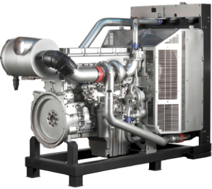
Perkins 2300 Series
Models 2306A-E14 and 2306C-E14
DIAGNOSTIC MANUAL
6 cylinder turbocharged diesel engine
Publication TSD 3457E, Issue 2.
© Proprietary information of Perkins Engines Company Limited, all rights reserved.
The information is correct at the time of print.
Published in December 2006 by Technical Publications,
Perkins Engines Company Limited, Peterborough PE1 5NA England.
Diagnostic Manual, TSD 3457E, Issue 2
i
This document is printed from SPI². Not for RESALE
![]()
![]()
![]()
Intermittent low power or power cut-outs
Test 6
Note: Use this procedure only if the engine DOES NOT shut down completely (the engine did not have to be
restarted).
Probable root causes
Speed setting input signal
Faulty electrical connections
Fuel supply
Note: If the problem only occurs under certain conditions (high engine speed, full load or engine operating
temperature, etc) then perform the test under those operating conditions.
Perform the following tests
1 Check the ECM connectors J1/P1 and J2/P2, customer connector, engine speed/timing sensor connectors
and the unit injector connectors and associated wiring for damage, abrasion, corrosion or incorrect attachment.
Refer to Test 39: Inspecting electrical connectors on page 82 for additional information.
2 Check the electronic service tool for a logged 168-02 Intermittent Battery Power to the ECM diagnostic code.
Check the battery connection at the customer connector and the ECM connector. Refer to the electrical
schematic. Perform a pull test on the customer connector. Perform a pull test on pins 48, 52, 53, 61, 63, 65
and 70. The wires should remain in the connectors during the pull test. Refer to Test 39: Inspecting electrical
connectors on page 82.
3 If the problem occurs only after the engine is warmed up and disappears after the engine has been allowed
to cool, the circuit breakers may be exceeding the trip point because of overheating. Check the circuit breakers
on the engine, reset if required.
Note: Aftermarket engine protection devices may interrupt power to the ECM. Check for correct installation
and operation of aftermarket engine protection devices. Aftermarket devices may need to be bypassed to
continue testing.
4 If a PWM speed control is fitted, connect an electronic service tool to the service tool connector. Turn the
key switch to the ON position, engine OFF. Check that a 91-08 Invalid Throttle Signal diagnostic code has not
been recently logged. Monitor the PWM input. The duty cycle should be between 5 and 10 percent at low load
and increase with load. If the throttle position change is erratic or out of range the problem is with the external
speed control.
5 Connect an electronic service tool and check that a 190-02 Loss of Engine Speed Signal diagnostic code is
not active. The code should not be active. If the 190-02 code is active check to see if a 342-02 Loss of Backup
Engine Speed Sensor diagnostic code has been recently logged. If the electronic service tool indicates that a
342-02 code has been recently logged perform a pull test on the wires to the backup engine speed/timing
sensor. Refer to Test 39: Inspecting electrical connectors on page 82. If a 342-02 code has not been recently
logged and the 190-02 code is active refer to Test 46: Engine speed/timing circuit test on page 126.
6 Check for a fuel supply problem and check fuel pressure. Refer to Test 29: Engine has a fuel supply problem
on page 65.
42
Diagnostic Manual, TSD 3457E, Issue 2
This document is printed from SPI². Not for RESALE
![]()
![]()
![]()
![]()
![]()
![]()
![]()
![]()
4
2300 Series
Electronic service tool will not communicate with the ECM
Test 7
Probable root causes
ECM software or ECM
Electronic service tool or communication adapter cable problem
Perkins Data Link
Electrical power supply to the ECM connector or wiring problem in electronic system wiring harness
Perform the following tests
Note: If the engine starts but will not communicate proceed with this test. If the engine will not start, refer to
Test 2: Engine cranks but will not start on page 38. If the engine will not crank, refer to Test 1: Engine will not
crank on page 37. Aftermarket engine protection devices may interrupt power to the ECM and prevent
communications with the electronic service tool. Check for correct installation and operation of aftermarket
protection devices, they may need to be bypassed to continue.
1 In the event that the ECM on the engine is new, the engine will not start or communicate until the ECM is
programmed. Refer to "Programming an ECM using flash programming" on page 27.
2 Check the ECM connectors J1/P1 and J2/P2, customer connector, service tool connectors and associated
wiring for damage, abrasion, corrosion or incorrect attachment. Refer to Test 39: Inspecting electrical
connectors on page 82 for additional information.
3 Check that the key switch is in the ON position and any override switches are not creating the problem. Start
the engine and then connect the electronic service tool. If communication occurs when the engine is started,
but not when the key switch is in the ON position, some type of system override is interrupting power to the
ECM. Repair as required.
4 Check that battery voltage is present at pin-A and Pin-B of the service tool connector (the communication
adapter power LED will be off if it is not receiving power).
5 Check the electronic service tool connections and wiring. Connect another electronic service tool and cable
to the system to check that the fault is with the electronic service tool.
6 Disconnect the ECM P1 connector. Install a bypass harness, connect the bypass harness directly to the
electronic service tool cable and retest. Refer to Test 45: Perkins Data Link circuit test on page 118. If the ECM
communicates with the bypass installed, either the machine wiring or another device is causing the data link
communication problem. Repair as required.
Diagnostic Manual, TSD 3457E, Issue 2
43
This document is printed from SPI². Not for RESALE
![]()
![]()
![]()
![]()
![]()
![]()
![]()
![]()
![]()
4
2300 Series
ECM will not accept factory passwords
Test 8
Probable root causes
Error entering password
Incorrect serial number (engine, ECM, or electronic service tool), total tattletale, or reason code used to
obtain password
Perform the following tests
1 Check that the correct passwords were entered. Check each character in the password for accuracy (for
instance letter I vs. number 1, Z vs. 2, O vs. 0, etc). Turn the key switch to the OFF position for 30 seconds
and then retry.
2 Check that the electronic service tool is on the "Factory Passwords" screen. Check the engine serial number
used to calculate the password is correct. Check the total tattletale, reason code, electronic service tool serial
number and ECM serial number is correct. Refer to "Factory passwords" on page 23 for more details.
44
Diagnostic Manual, TSD 3457E, Issue 2
This document is printed from SPI². Not for RESALE
![]()
![]()
![]()
![]()
![]()
![]()
![]()
4
2300 Series
Excessive black smoke
Test 9
Probable root causes
Air inlet restriction or air system leaks
Engine speed/timing signal: injection timing or calibration, incorrect engine speed/timing wheel orientation
assembly, engine speed/timing sensor calibration error after replacement
Faulty inlet air manifold pressure sensor, atmospheric pressure sensor, or sensor calibration
ECM/software problem
Fuel supply: low supply pressure, air in low pressure fuel system, poor fuel quality
Incorrect valve adjustment
Perform the following tests
1 Connect an electronic service tool and compare atmospheric and inlet pressure readings. Check for filter
restriction derates and alarms. Check air inlet and exhaust systems for restrictions and leaks. Check for a failed
turbocharger. Refer to the relevant procedure in the Workshop Manual. Replace plugged air filters, or clean
filters, as described in the User’s Handbook, and repair any leaks found. Check for correct operation of the
inlet air manifold pressure and atmospheric pressure sensors. Refer to Test 41: Analogue sensor open or
short circuit test on page 91.
2 Check calibration of the engine speed/timing sensor, recalibrate if required. Refer to Test 47: Engine speed/
timing calibration on page 134. Check for correct orientation between crankshaft and camshaft drive gears,
repair as required. Refer to the relevant procedure in the Workshop Manual.
3 Monitor atmospheric pressure with an electronic service tool. Observe inlet air manifold pressure, fuel
position, rated fuel position and smoke fuel limit while the engine is operating under full load.
Fuel position = rated fuel position
and
smoke fuel limit > rated fuel limit
Note: A problem with the smoke fuel limit will only create black smoke problems on acceleration, not steady
state operation. Check for a restriction in the atmosphere path, remove dirt and debris if required. Atmospheric
2
pressure should range from 50 to 100 kPa (7.5 to 15 lb/in ) depending on your area of operation. Refer to Test
41: Analogue sensor open or short circuit test on page 91.
4 Check for a fuel supply problem and check the fuel pressure. Refer to Test 29: Engine has a fuel supply
problem on page 65.
5 Check valve adjustment.
Diagnostic Manual, TSD 3457E, Issue 2
45
This document is printed from SPI². Not for RESALE
![]()
![]()
![]()
![]()
![]()
![]()
![]()
![]()
![]()
![]()
![]()
4
2300 Series
Excessive white smoke
Test 10
Note: Some white smoke may be present during cold start-up conditions when the engine is operating
normally.
Probable root cause
Faulty coolant temperature sensor
Engine speed/timing signal: injection timing or calibration, incorrect engine speed/timing wheel orientation
assembly, engine speed/timing sensor calibration error after replacement
ECM software
Fuel supply
Combustion system problem
Perform the following tests
1 Check for a fuel supply problem and check the fuel pressure. Refer to Test 29: Engine has a fuel supply
problem on page 65.
2 Ensure that the correct type of fuel is used and check that there is no water or other contaminants in the fuel.
3 Check that cold mode is active when the engine is cold. Monitor coolant temperature status on an electronic
service tool. Observe coolant temperature and ensure the reading is reasonable. If temperature reading is
incorrect, refer to Test 41: Analogue sensor open or short circuit test on page 91.
4 Check timing calibration of the engine speed/timing sensor, recalibrate if required. Refer to Test 47: Engine
speed/timing calibration on page 134. Check for correct orientation between crankshaft and camshaft drive
gears, repair as required.
5 Connect an electronic service tool and check that the correct software is installed for the engine
configuration and application. Refer to Chapter 3, Programming parameters.
6 Excessive valve, piston, ring and/or liner wear, or low cranking speed can result in reduced compression
pressure, resulting in white smoke. Coolant leakage into the cylinder or exhaust system can also produce
symptoms similar to white smoke emissions from unburned fuel. Refer to the Workshop Manual.
46
Diagnostic Manual, TSD 3457E, Issue 2
This document is printed from SPI². Not for RESALE
![]()
![]()
![]()
![]()
![]()
![]()
![]()
![]()
![]()
![]()
4
2300 Series
Excessive blue smoke
Test 11
Note: Blue smoke is produced by the engine when there is excessive oil in the cylinder bores.
Probable root cause
Too much engine oil in the sump
Air inlet or exhaust restriction
Loose, worn or damaged turbocharger
Combustion system problem
Perform the following tests
1 Check that the engine oil level is correct. If necessary, drain the engine oil until the correct level is obtained.
2 Check the crankcase breather for blockages or restrictions.
3 Check the air filter restriction indicator. Ensure that the filter element of the air cleaner is clean and
serviceable.
4 Check the air inlet and exhaust systems for blockages, restrictions or damage to pipes and hoses.
5 Check that the turbocharger mountings are not loose.
6 Check the turbine housing of the turbocharger for excessive dirt or carbon.
7 Check for worn turbocharger bearings.
8 Check the turbine blades for damage and ensure that the turbine rotates freely.
9 Check the compressor housing for indications of oil.
10 Check that the valve clearances are correct and adjust if necessary.
11 Refer to the Workshop Manual; low compression can be caused by:
Broken, worn or sticking piston rings
Worn cylinder bores
Worn valves, valve stem seals or valve guides
Valves not fully closed
Cylinder head gasket faulty
Cracked cylinder head
Diagnostic Manual, TSD 3457E, Issue 2
47
This document is printed from SPI². Not for RESALE
![]()
![]()
![]()
![]()
![]()
![]()
![]()
![]()
![]()
![]()
![]()
![]()
![]()
![]()
![]()
4
2300 Series
Engine cannot reach correct rev/min
Test 12
Note: If this problem occurs only under load, refer to Test 4: Low power/poor or no response to throttle on
page 40.
Probable root causes
Engine is in cold mode or derated
ECM software
External speed control input
Faulty intake manifold pressure sensor, atmosphere signal or calibration
Fuel supply
Air inlet or exhaust restriction or air system leaks
Air supply/low boost
Perform the following tests
1 Connect an electronic service tool and check that the engine has exited cold mode. Check for active engine
derates. Check that the programming parameters are correct. Refer to Chapter 3, Programming parameters.
Note: The engine may be derated due to altitude or other factors.
2 Monitor the external speed control (if fitted) on an electronic service tool. Observe the position and check
that it can reach 100 percent.
Note: If PWM or analogue speed controls are selected, i.e. digital speed control not installed, but the selected
PWM or analogue control is not connected, the engine will run at 1100 rpm.
3 Check for a fuel supply problem and check the fuel pressure. Refer to Test 29: Engine has a fuel supply
problem on page 65.
4 Check air inlet and exhaust systems for restrictions and leaks. Look for a diagnostic lamp indication, or
tripped restriction indicators (if fitted) associated with plugged air filters. Replace plugged air filters, or clean
filters, as described in the User’s Handbook, and repair any leaks found. Also refer to Test 41: Analogue
sensor open or short circuit test on page 91.
48
Diagnostic Manual, TSD 3457E, Issue 2
This document is printed from SPI². Not for RESALE
![]()
![]()
![]()
![]()
![]()
![]()
![]()
![]()
![]()
![]()
![]()
![]()
4
2300 Series
Poor acceleration or response
Test 13
Probable root causes
The engine is in cold mode or a derate mode.
ECM software
External speed control input
Incorrect intake manifold pressure sensor or atmosphere signal
Air inlet or exhaust restriction or leaks
Fuel supply
Perform the following tests
1 Connect an electronic service tool. Check that the engine has exited cold mode operation. The engine will
not respond as fast until it has warmed to operating temperature.
2 Check that the correct ECM software is installed. Refer to Chapter 3, Programming parameters.
3 Monitor the external speed control input on an electronic service tool. Observe position and check that the
reading is stable and can reach 100 percent.
4 Inspect ECM connectors J1/P1 and J2/P2, engine interface connectors, and the unit injector connectors for
correct connection. Repair or replace as required. Refer to Test 39: Inspecting electrical connectors on page
82. Perform the cylinder cut-out test to check for any non-operable unit injectors, and replace only those
diagnosed as faulty by the cylinder cut-out check. Connect an electronic service tool and cut-out each cylinder
to isolate the misfiring cylinder(s). If results are inconclusive, perform the test under load or shut off half of the
engine's cylinders and repeat cut-out on the remaining active cylinders to locate those misfiring. If it can be
isolated to a specific cylinder(s), refer to Test 48: Injector solenoids circuit test on page 138.
5 Monitor atmospheric pressure with an electronic service tool. Observe intake manifold pressure while the
2
engine is operating under full load. Atmospheric pressure should range from 50 to 100 kPa (7.5 to 15 lb/in ).
6 Check air inlet and exhaust systems for restrictions and leaks. Look for a warning lamp or diagnostic lamp
indication, or tripped restriction indicators (if fitted) associated with plugged air filters. Replace plugged air
filters, or clean filters, as described in the User’s Handbook, and repair any leaks found.
7 Check for a fuel supply problem and check the fuel pressure. Refer to Test 29: Engine has a fuel supply
problem on page 65.
Diagnostic Manual, TSD 3457E, Issue 2
49
This document is printed from SPI². Not for RESALE
![]()
![]()
![]()
![]()
![]()
![]()
![]()
![]()
![]()
![]()
![]()
4
2300 Series
Poor fuel consumption
Test 14
Note: This is NOT an electronic system problem. Refer to the Workshop Manual for additional information on
the following tests.
Probable root causes
Incorrect engine operation
Engine speed/timing signal: injection timing or calibration, incorrect engine speed/timing wheel orientation,
engine speed/timing sensor calibration error after replacement
Faulty electronic unit injector(s) (individual cylinder malfunction)
Fuel supply
Air inlet or exhaust restrictions or air system leaks
Perform the following tests
1 Check timing calibration of engine speed/timing sensor and recalibrate if required. Refer to Test 47: Engine
speed/timing calibration on page 134. Check for correct orientation between crankshaft and camshaft drive
gears, repair as required. Refer to the Workshop Manual.
2 Inspect ECM connector J2/P2 and the unit injector connector for correct connection. Refer to Test 39:
Inspecting electrical connectors on page 82. Connect an electronic service tool and cut out each cylinder to
isolate the misfiring cylinder(s). If results are inconclusive, shut off half of the engine's cylinders and repeat cut-
out on remaining active cylinders to locate those that are misfiring. Refer to Test 48: Injector solenoids circuit
test on page 138.
3 Check for a fuel supply problem and check the fuel pressure. Refer to Test 29: Engine has a fuel supply
problem on page 65.
4 Check air inlet and exhaust systems for restrictions and leaks. Look for a warning lamp or diagnostic lamp
indication, or tripped restriction indicators (fitted) associated with plugged air filters. Replace plugged air filters,
or clean filters, as described in the User’s Handbook, and repair any leaks found.
50
Diagnostic Manual, TSD 3457E, Issue 2
This document is printed from SPI². Not for RESALE
![]()
![]()
![]()
![]()
![]()
![]()
![]()
![]()
![]()
![]()
4
2300 Series
Too much vibration
Test 15
Note: This is NOT an electronic system problem. Refer to the Workshop Manual for additional information on
the following tests.
Possible root causes
Loose or faulty vibration damper
Engine supports are loose, wrong or are incorrectly torqued
Equipment may not be in alignment or is out of balance
Engine misfiring or running rough
Perform the following tests
1 Check vibration damper for damage. Tighten bolts. If vibration damper bolt holes have damage or wear,
replace with new parts. Install a new vibration damper if necessary.
2 Run the engine through its speed range while looking for loose or broken mounts or brackets. Tighten all
mounting bolts. Install new components if necessary.
3 Check alignment and balance, correct if required.
4 Refer to Test 3: Engine misfires, runs rough or is unstable on page 39.
Diagnostic Manual, TSD 3457E, Issue 2
51
This document is printed from SPI². Not for RESALE
![]()
![]()
![]()
![]()
![]()
![]()
![]()
![]()
![]()
4
2300 Series
Noise coming from cylinder
Test 16
Note: This is NOT an electronic system problem. Refer to the Workshop Manual for additional information on
the following tests.
Probable root causes
Low quality fuel
Incorrect fuel injection timing calibration
Faulty electronic unit injector(s)
Incorrect valve train operation or valve train noise (clicking)
Damage to valve spring(s) or locks
Not enough lubrication
Loud tapping sound from rocker cover
Damage to valve(s)
Unit injector plunger
Damaged camshaft lobe
Little or no valve clearance, worn valve seat or face of valve
Perform the following tests
1 Check for a fuel supply problem and check the fuel pressure. Refer to Test 29: Engine has a fuel supply
problem on page 65.
2 Check and calibrate electronic injection timing with an electronic service tool. Refer to Test 47: Engine
speed/timing calibration on page 134.
3 Connect an electronic service tool and cut-out each cylinder to isolate the misfiring cylinder(s). If results are
inconclusive, perform test under load or shut off half of the engine's cylinders and repeat cut-out on remaining
active cylinders to locate those misfiring. Refer to Test 48: Injector solenoids circuit test on page 138.
4 Damage to valve spring(s). Replace damaged parts. Damage to camshaft. Replace damaged parts. Clean
engine valve train thoroughly. Replace damaged valve lifters. Inspect camshaft lobes for damage. Look for
valves that do not move freely. Adjust using the procedure in the Workshop Manual. Refer to Test 18: Valve
rotocoil or spring lock is free on page 54.
5 Install new parts where necessary.
Caution: Broken locks can cause the valve to fall into the cylinder.This will cause severe damage.
6 Check lubrication in valve compartment. There must be a strong flow of oil at high engine idle rev/min, but
only a small flow of oil at low rev/min. Oil passages must be clean, especially those that send oil to the cylinder
head.
7 Refer to Test 17: Excessive valve clearance on page 53. Adjust using the procedure in the Workshop
Manual.
8 Replace the valve(s) and adjust using the procedure in the Workshop Manual.
9 Plunger may be stuck, repair as required with reference to the Workshop Manual.
10 Refer to the Workshop Manual.
11 Reconditioning of cylinder head is required.
52
Diagnostic Manual, TSD 3457E, Issue 2
This document is printed from SPI². Not for RESALE
![]()
![]()
![]()
![]()
![]()
![]()
![]()
![]()
![]()
![]()
![]()
![]()
![]()
![]()
![]()
![]()
4
2300 Series
Excessive valve clearance
Test 17
Note: This is NOT an electronic system problem. Refer to the Workshop Manual for additional information on
the following tests.
Probable root causes
Not enough lubrication
Rocker arm worn at face that contacts bridge
Bridges for valves worn/incorrect adjustment
End of valve stem worn
Worn cams on camshaft
Loose or broken rocker shaft retaining bolt
Perform the following tests
1 Check lubrication in valve compartment. There must be a strong flow of oil at high engine idle rev/min, but
only a small flow at low rev/min. Oil passages must be clean.
2 If there is too much wear, install new parts or rocker arms. Adjust valve clearance using the procedure in
the Workshop Manual.
3 Adjust or replace bridges as necessary. If there is too much wear, install new parts. Adjust valve clearance
using the procedure in the Workshop Manual.
4 If there is too much wear, adjust valve clearance using the procedure in the Workshop Manual.
5 Clean engine valve train thoroughly. Check camshaft for wear. Check for free movement of valves or bent
valve stem. Adjust using the procedure in the Workshop Manual.
6 Check valve clearance. Check for free movement of valves or bent valve stems. Install a new camshaft.
Adjust using the procedure in the Workshop Manual.
7 Repair or replace rocker shaft retaining bolt as required.
Diagnostic Manual, TSD 3457E, Issue 2
53
This document is printed from SPI². Not for RESALE
![]()
![]()
![]()
![]()
![]()
![]()
![]()
![]()
![]()
![]()
![]()
4
2300 Series
Valve rotocoil or spring lock is free
Test 18
Note: This is NOT an electronic system problem. Refer to the Workshop Manual for additional information on
the following tests.
Probable root causes
Cracked inlet valve Rotocoil
Broken spring locks
Broken valve spring(s)
Broken valve
Perform the following tests
1 Determine cause of engine overspeed that would crack the Rotocoil.
2 Install new parts where necessary.
Caution: Broken locks can cause the valve to fall into the cylinder, and will cause severe damage.
3 Install new valve spring(s).
4 Replace valve and other damaged parts.
54
Diagnostic Manual, TSD 3457E, Issue 2
This document is printed from SPI². Not for RESALE
![]()
![]()
![]()
![]()
![]()
![]()
![]()
![]()
![]()
4
2300 Series
Mechanical noise (knock) in engine
Test 19
Note: This is NOT an electronic system problem. Refer to the Workshop Manual for additional information on
the following tests.
Probable root causes
Faulty accessory or driven equipment
Damaged camshaft lobe
Damaged gears
Failure of bearing for connecting rod or damaged crankshaft
Perform the following tests
1 Attempt to isolate the source of the noise. If suspected, remove and inspect engine accessories. Repair or
renew as necessary. Refer to the Workshop Manual.
2 If noise may be coming out of the cylinder head, check for damage to camshaft or valve train components.
Replace damaged parts. Clean the engine valve train thoroughly. Check for valves that do not move freely.
Adjust using the procedure in the Workshop Manual. Refer to Test 16: Noise coming from cylinder on page 52.
3 Install new parts where necessary.
4 Inspect the connecting rod bearings and the bearing surfaces (journals) on the crankshaft. Install new parts
where necessary.
Diagnostic Manual, TSD 3457E, Issue 2
55
This document is printed from SPI². Not for RESALE
![]()
![]()
![]()
![]()
![]()
![]()
![]()
![]()
![]()
4
2300 Series
Oil in cooling system
Test 20
Note: This is NOT an electronic system problem. Refer to the Workshop Manual for additional information on
the following tests.
Probable root causes
Faulty engine oil cooler core or driven equipment oil cooler (if fitted)
Failure of cylinder head gasket or coolant seals
Perform the following tests
1 Inspect each cooler and replace or repair faulty oil cooler.
2 Check cylinder liner projection. Install a new cylinder head gasket and new coolant seals in the spacer plate.
Tighten the cylinder head bolts according to the procedure in the Workshop Manual.
56
Diagnostic Manual, TSD 3457E, Issue 2
This document is printed from SPI². Not for RESALE
![]()
![]()
![]()
![]()
![]()
![]()
![]()
4
2300 Series
Fuel in cooling system
Test 21
Note: This is NOT an electronic system problem. Refer to the Workshop Manual for additional information on
the following tests.
Probable root causes
Internal cylinder head problem
Perform the following tests
1 Remove the valve cover. Remove the fuel supply and fuel return line from cylinder head. Cap the fuel return
2
connector and apply 700 kPa (100 lb/in ) maximum air pressure to the fuel supply connector. Check for fuel
leakage around the unit injector. If leakage is present, it will be necessary to remove the unit injector and install
a new O-Ring seal.
Diagnostic Manual, TSD 3457E, Issue 2
57
This document is printed from SPI². Not for RESALE
![]()
![]()
![]()
![]()
![]()
![]()
4
2300 Series
Coolant in lubricating oil
Test 22
Note: This is NOT an electronic system problem. Refer to the Workshop Manual for additional information on
the following tests.
Probable root causes
Failure of any of the oil cooler cores
Failure of cylinder head gasket or coolant seals
Crack in cylinder head
Cracked or broken cylinder liner
Crack in cylinder block
Perform the following tests
1 Install a new oil cooler core. Drain crankcase and refill with clean lubricant. Install new oil filters.
2 Check cylinder liner projection. Install a new cylinder head gasket and new liner coolant seals in the spacer
plate. Tighten the cylinder head bolts according to the procedure in the Workshop Manual.
3 Check for cracks in cylinder head. Repair or replace as required.
4 Check for cracked liners. Replace cracked cylinder liners.
5 Repair or replace cylinder block.
58
Diagnostic Manual, TSD 3457E, Issue 2
This document is printed from SPI². Not for RESALE
![]()
![]()
![]()
![]()
![]()
![]()
![]()
![]()
![]()
![]()
4
2300 Series
Fuel dilution of lubricating oil
Test 23
Note: This is NOT an electronic system problem. Refer to the Workshop Manual for additional information on
the following tests.
Probable root causes
Leaking fuel seals on unit injector case or barrel
Leaking fuel seals on cylinder head adapters
Unit injector nozzle tip leakage or breakage
Cracked fuel supply manifold
Fuel transfer pump seal leaking with plugged weep hole
Perform the following tests
1 Inspect for signs of damage to unit injector fuel seals, replace if required.
2 Inspect for signs of damage to cylinder head fuel seals, replace if required.
3 Inspect for signs of unit injector damage, replace as required.
4 Inspect for signs of fuel supply manifold damage, replace if required.
5 Repair or replace fuel lift pump.
Diagnostic Manual, TSD 3457E, Issue 2
59
This document is printed from SPI². Not for RESALE
![]()
![]()
![]()
![]()
![]()
![]()
![]()
![]()
![]()
![]()
4
2300 Series
Engine has early wear
Test 24
Note: This is NOT an electronic system problem. Refer to the Workshop Manual for additional information on
the following tests.
Probable root causes
Dirt in lubricating oil
Air inlet leaks
Fuel leakage into lubricating oil
Low oil pressure
Perform the following tests
1 Remove dirty lubricating oil. Install new filters. Put clean oil in the engine. Check oil filter bypass valve for a
weak or broken spring.
2 Inspect all gaskets and connections. Repair if leaks are found.
3 Fuel leakage into lubricating oil will cause high fuel consumption and low engine oil pressure. This condition
may also increase the oil level in the crankcase. Refer to Test 23: Fuel dilution of lubricating oil on page 59.
4 Refer to Test 25: Engine has low oil pressure on page 61.
60
Diagnostic Manual, TSD 3457E, Issue 2
This document is printed from SPI². Not for RESALE
![]()
![]()
![]()
![]()
![]()
![]()
![]()
![]()
![]()
4
2300 Series
Engine has low oil pressure
Test 25
Note: This is NOT an electronic system problem. Refer to the Workshop Manual for additional information on
the following tests.
Caution: Do not operate engine with low oil pressure, engine damage will result. If measured oil pressure is
low, discontinue engine operation until the problem is corrected.
Probable root causes
Low Engine Oil Pressure Warning (event code) 360-01
Oil pressure data is below normal operating range for two seconds. The fault and event will be active, and
logged only if the engine has been running for at least 15 seconds. The warning lamp is also illuminated.
Low Engine Oil Pressure Action Alert (event code) 360-02
Oil pressure data is below normal operating range for two seconds. The fault and event will be logged.
Low Engine Oil Pressure Shutdown (event code) 360-03
Engine oil pressure has reached a level where the engine is shutdown unless critical override is active.
Oil level may be too low
Dirty oil filters or restriction in oil cooler(s)
Diesel fuel in lubricating oil
Oil pressure relief valve does not close
Oil pump suction pipe problem, faulty oil pump or scavenge oil pump
Too much clearance between rocker arm shaft and rocker arms
Too much clearance between camshaft and camshaft bearings
Too much clearance between crankshaft and crankshaft bearings
Perform the following tests
1 Add oil if required.
2 Check the operation of the bypass valve for the filter. Install new oil filters i, f required. Clean or install new
oil cooler core(s). Remove dirty oil from the engine. Put clean oil in the engine.
3 Check for presence of fuel in lubricating oil. Refer to Test 23: Fuel dilution of lubricating oil on page 59.
4 Clean the bypass valve and housing. Install new parts as necessary.
5 Check the oil pump inlet screen for obstructions. Check for air leakage into the supply to the oil pump.
Examine oil pump for excessive wear. Repair or replace as needed.
6 Install new camshaft and camshaft bearings if necessary.
7 Inspect the main bearings and replace as necessary.
Diagnostic Manual, TSD 3457E, Issue 2
61
This document is printed from SPI². Not for RESALE
![]()
![]()
![]()
![]()
![]()
![]()
![]()
![]()
![]()
![]()
![]()
![]()
![]()
![]()
![]()
![]()
4
2300 Series
Engine uses too much lubricating oil
Test 26
Note: This is NOT an electronic system problem. Refer to the Workshop Manual for additional information on
the following tests.
Probable root causes
Oil leaks
Too much lubricating oil in engine
Oil temperature is too high
Too much oil in the valve compartment
Turbocharger seal ring failure
Worn valve guides
Worn piston rings
Perform the following tests
1 Find all oil leaks. Repair as required. Check for dirty crankcase breather(s).
2 Remove extra oil. Find where extra fluid comes from. Repair as required. Put correct amount of oil in engine.
3 Check for restrictions in the oil cooler or an oil cooler bypass valve stuck in the open position.
4 Check for high coolant temperature. Refer to Test 27: Engine coolant is too hot on page 63.
5 Check that the dowel is installed in the left bolt hole of the rocker shaft. This dowel is located between the
rocker shaft and valve cover base. Check shaft and valve cover base. Check for dirty breather element.
6 Check inlet manifold for oil and repair the turbocharger if necessary.
7 Reconditioning of the cylinder head is required.
8 Inspect and install new parts as required.
62
Diagnostic Manual, TSD 3457E, Issue 2
This document is printed from SPI². Not for RESALE
![]()
![]()
![]()
![]()
![]()
![]()
![]()
![]()
![]()
![]()
![]()
![]()
4
2300 Series
Engine coolant is too hot
Test 27
Note: This is NOT an electronic system problem. Refer to the Workshop Manual for additional information on
the following tests.
Probable root causes
High Coolant Temperature Warning (event code) 361-01
The engine is running, the coolant temperature sensor reading is greater than or equal to the preset
temperature for two seconds. Diagnostic codes 262-03 +5V Supply Above Normal or 262-04 +5V Supply
Below Normal are not active.
High Coolant Temperature Action Alert (event code) 361-02
The coolant temperature sensor reading is greater than or equal to the preset temperature for two seconds.
Diagnostic code 262-03 +5V Supply Above Normal is not active. The fault and event will be logged.
High Coolant Temperature Shutdown (event code) 360-03
Engine coolant temperature has reached a level where the engine is shutdown unless Critical Override is
active.
Radiator damage or obstruction
Low coolant level in system
Combustion gases in coolant
Incorrect fuel injection timing calibration
Faulty coolant thermostats
Faulty coolant pump
Too much load on the system
Perform the following tests
1 Clean obstructions from the radiator; check that there are no restrictions to the air flow.
2 Check that the fan belts are not slipping.
3 Add coolant to cooling system. Check for leaks.
4 Inspect coolant for presence of bubbles.
5 Check coolant thermostats for correct operation. Inspect coolant pump impeller vanes for damage or
erosion. Repair as necessary.
6 Reduce the load.
Diagnostic Manual, TSD 3457E, Issue 2
63
This document is printed from SPI². Not for RESALE
![]()
![]()
![]()
![]()
![]()
![]()
![]()
![]()
![]()
![]()
![]()
![]()
![]()
![]()
![]()
4
2300 Series
Oil at the exhaust
Test 28
Note: This is NOT an electronic system problem. Refer to the Workshop Manual for additional information on
the following tests.
Probable root causes
Turbocharger seal ring failure
Too much oil in the valve compartment
Worn valve guides
Worn piston rings
Perform the following tests
1 Check inlet manifold for oil and repair the turbocharger if necessary.
2 Check that the dowel is installed in the left bolt hole of the rocker shaft.
3 Reconditioning of the cylinder head is required.
4 Inspect and install new parts as required.
64
Diagnostic Manual, TSD 3457E, Issue 2
This document is printed from SPI². Not for RESALE
![]()
![]()
![]()
![]()
![]()
![]()
![]()
![]()
![]()
4
2300 Series
Engine has a fuel supply problem
Test 29
Note: This is NOT an electronic system problem. Refer to the Workshop Manual for additional information on
the following tests.
Probable root causes
Low fuel level
Poor fuel quality
Unit injector priming problem
Low supply pressure
Fuel supply circuit
Incorrect fuel type
Water in fuel
Perform the following tests
1 Visually check fuel level (do not rely on fuel gauge only). Check the fuel pressure.
2 In temperatures below 0 °C (32 °F) check for congealed fuel (wax). Check fuel tank for foreign objects which
may block the fuel supply.
3 Check for fuel line restrictions and repair or replace as required. Refer to the Workshop Manual.
4 Monitor exhaust for smoke while cranking. If smoke is not present there may be a fuel supply problem.
5 Check for air in the low pressure fuel supply system. Purge air from the low pressure fuel supply circuit with
the hand priming pump and cranking the engine in 30 second cycles, pausing at least 2 minutes between
cranking cycles to allow the starter motor to cool. Loosen low pressure fuel line fitting on inlet to pressure
regulating valve and hand prime again if air in fuel continues. Also, use of a sight glass in the low pressure
supply line can be helpful in diagnosing air in the fuel.
6 Check fuel pressure after the filter in the supply circuit during cranking. Refer to the Workshop Manual for
correct pressure values. If pressure is low, check for plugged fuel filters. If pressure is still low, repair or replace
fuel lift pump, fuel lift pump coupling, and fuel pressure regulating valve as needed.
7 Check for air in the low pressure fuel supply system after replacing filters, working on the low pressure fuel
supply circuit or replacing unit injectors. Check fuel pressure after the filter in the supply circuit during cranking.
Refer to the Workshop Manual for correct pressure values. If pressure is low, check for plugged fuel filters. If
pressure is still low, repair or replace fuel lift pump, fuel lift pump coupling, and fuel pressure regulating valve
as needed.
Diagnostic Manual, TSD 3457E, Issue 2
65
This document is printed from SPI². Not for RESALE
![]()
![]()
![]()
![]()
![]()
![]()
![]()
![]()
![]()
![]()
![]()
![]()
4
2300 Series
Indicator lamp not functioning correctly
Probable root causes
Test 30
Notes:
For details regarding wiring harness refer to the engine electrical schematic. This wiring is the responsibility
of the OEM.
Faulty bulb
Engine wiring
Battery voltage
Perform the following tests
1 Turn key switch OFF and check ECM connector J1/P1 and associated wiring for damage, abrasion,
corrosion or incorrect attachment. Refer to Test 39: Inspecting electrical connectors on page 82.
2 Measure the voltage between (+Battery) and (-Battery) at ECM connector J1/P1. The voltage should be
between 22.0 and 27.0 Volts DC for a 24 Volt system. If the voltage is out of range refer to Test 40: Electrical
power supply to the ECM on page 88.
3 Connect a jumper wire between the suspect lamp driver of ECM connector J1/P1 and (-Battery) for J1/28 to
J1/31 or (+Battery) for J1/10, J1/19 and J1/20. If the lamp illuminates the circuit is functioning normally but the
ECM is not completing the lamp circuit. Refer to Test 40: Electrical power supply to the ECM on page 88.
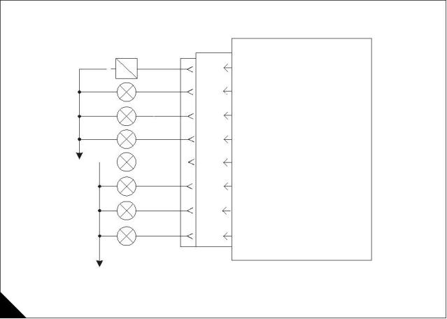
Indicator lamp schematic
Outputs may be used to drive lamps or relays. Refer to the wiring diagrams for full connection details.
Note: If very low current lamps or LED’s are connected to these outputs, a diagnostic code may be generated
even if the lamps or LED’s are functioning correctly.
ECM
Crank
Terminate
J1/13
J1/10
Crank Terminate Output
Shutdown Lamp Output
Shutdown
Action Alert
Warning
Action Alert Lamp Output
Warning Lamp Output
J1/19
J1/20
J1/31
J1/28
J1/29
System Fault
Oil Pressure
Coolant Temp
Diagnostic Lamp Output
Oil Pressure Lamp Output
Coolant Temperature Lamp Output
Overspeed Lamp Output
B-
Overspeed
J1/30
P1 J1
B+
A
HA0008
66
Diagnostic Manual, TSD 3457E, Issue 2
This document is printed from SPI². Not for RESALE
![]()
![]()
![]()
![]()
![]()
![]()
![]()
![]()
![]()
4
2300 Series
Inlet air manifold temperature is too high
Test 31
Note: This is NOT an electronic system problem. Refer to the Workshop Manual for additional information on
the following tests.
Probable root causes
High Inlet Air Temperature Warning (event code) 368-01
The engine is running, the inlet air manifold temperature sensor reading is greater than the preset level for two
seconds. Diagnostic codes 262-03 +5 V Supply Above Normal or 262-04 +5 V Supply Below Normal are not
active. The event code and diagnostic code will be logged.
High Inlet Air Temperature Action Alert (event code) 368-02
The engine is running, the inlet air manifold temperature sensor reading is greater than or equal to the preset
level for at least two seconds. Diagnostic codes 262-03 +5 V Supply Above Normal or 262-04 +5 V Supply
Below Normal are not active. The event code and diagnostic code will be logged.
Incorrect fuel injection timing calibration
Low air inlet system pressure
Air inlet system has a restriction
Perform the following tests
1 Connect an electronic service tool and check for engine speed/timing error. Test 47: Engine speed/timing
calibration on page 134.
2 Check pressure in the air inlet manifold. Check for air inlet leaks. Look for restrictions at the air cleaner.
Check for leaks between inlet manifold and turbocharger. Repair or renew as necessary.
3 Check for air inlet restrictions. Refer to the Workshop Manual. Repair as necessary.
Diagnostic Manual, TSD 3457E, Issue 2
67
This document is printed from SPI². Not for RESALE
![]()
![]()
![]()
![]()
![]()
![]()
![]()
![]()
![]()
![]()
4
2300 Series
Engine has a high fuel temperature
Test 32
Note: This is NOT an electronic system problem. Refer to the Workshop Manual for additional information on
the following tests.
Probable root causes
High Fuel Temp Warning (event code) 363-01
The engine speed is greater than 1000 rev/min, the fuel temperature sensor reading is greater than 60 °C
(140 °F) for 30 seconds. Diagnostic codes 262-03 +5V Supply Above Normal or 262-04 +5V Supply Below
Normal are not active. The event code and diagnostic code will be logged and the warning lamp is illuminated.
Incorrect sensor installation
Low fuel level
Poor fuel quality
Low supply pressure
Insufficient size of fuel tank
A fuel cooler may be required
Perform the following tests
1 Check that the fuel temperature sensor has been correctly installed. Refer to the Workshop Manual.
2 Refer to Test 29: Engine has a fuel supply problem on page 65.
68
Diagnostic Manual, TSD 3457E, Issue 2
This document is printed from SPI². Not for RESALE
![]()
![]()
![]()
![]()
![]()
![]()
![]()
![]()
![]()
![]()
![]()
![]()
4
2300 Series
Diagnostic procedures with an event code
General information
This section is to be used for diagnosing problems that have event codes but do not have ACTIVE diagnostic
codes.
Event codes
Event codes indicate an actual engine fault, e.g. low oil pressure, rather than an electronic component failure.
There are three possible levels of severity of the fault.
Level 1 - Operator Warning
To warn the operator or machine control system of a possible condition that requires operator attention.
Level 2 - Action (Derate or Alert)
To inform the operator or machine control system to take action to enable the correct control of the system. In
most cases the OEM will use this level for a controlled shutdown of the engine in order to protect it from
damage.
Note: There are no derates set on the 2806/2306 engines. The TIPSS/EST Service Tool incorrectly shows
Action Alerts as Derates on certain screens.
Level 3 - Shutdown
At this level the ECM will immediately stop the engine unless critical override is enabled and signal that a
critical fault level has been reached.
Caution: If critical override is enabled the product is now operating in a condition outside its scope of supply
and may cause injury or be damaged in such a way as to invalidate the warranty.
Diagnostic Manual, TSD 3457E, Issue 2
69
This document is printed from SPI². Not for RESALE
![]()
![]()
![]()
4
2300 Series
Diagnostic tests
High intake manifold pressure
Test 33
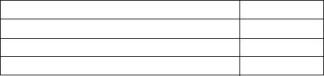
Event
Code
E162-1
E162-2
High intake manifold pressure Warning
High intake manifold pressure Action Alert
Probable root causes
Engine overload
Perform the following tests
1 Intake manifold pressure sensor circuit
Check the intake manifold pressure reading with TIPSS-EST and ensure it is reasonable. The pressure should
decrease as load decreases. If the reading is not correct, diagnose the sensor circuit.
70
Diagnostic Manual, TSD 3457E, Issue 2
This document is printed from SPI². Not for RESALE
![]()
![]()
![]()
![]()
![]()
![]()

4
2300 Series
Low oil pressure
Test 34
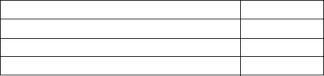
Event
Code
E360-1
E360-2
E360-3
Low oil pressure Warning
Low oil pressure Action Alert
Low oil pressure Shutdown
Probable root causes
Low oil level
High oil temperature/low viscosity
Blocked oil filter
Oil pressure sensor circuit
Blocked oil cooler
Faulty oil pump/oil pump bypass valve
Perform the following tests
1 Low oil level
Check oil level and add oil as necessary.
2 High oil temperature/low viscosity
If present, diagnose the oil cooler circuit. High oil temperature causes oil viscosity to be low which can cause
low oil pressure.
3 Blocked oil filter
Replace oil filters if there is any doubt as to their condition
4 Oil pressure sensor circuit
Diagnose the sensor circuit.
5 Blocked oil cooler
An oil cooler restriction can cause low oil pressure and high oil temperature.
Diagnostic Manual, TSD 3457E, Issue 2
71
This document is printed from SPI². Not for RESALE
![]()
![]()
![]()
![]()
![]()
![]()
![]()
![]()
![]()
![]()
![]()
4
2300 Series
High coolant temperature
Test 35
Event
Code
High coolant temperature Warning
High coolant temperature Action Alert
High coolant temperature Shutdown
E361-1
E361-2
E361-3
Probable root causes
High ambient temperature
Low coolant level/cooling system leaks
Insufficient air or coolant flow through heat exchanger or radiator
Faulty coolant thermostats
Coolant temperature sensor circuit
Insufficient coolant flow
High inlet air temperature
Exhaust restriction
Combustion gasses in coolant
Perform the following tests
1 High ambient temperature
Determine if ambient air temperature is within design specifications for the cooling system.
2 Low coolant level/cooling system leaks
Check coolant level. Low coolant level can be the effect of overheating rather than the cause. Run the engine
to operating temperature and determine if leaks occur before the engine overheats.
3 Insufficient air or coolant flow through heat exchanger or radiator
Check radiator cooling fins for obstructions. Check radiator cooling fan (if fitted) operation. Check for sufficient
flow and temperature of coolant through the heat exchanger (if fitted).
4 Faulty coolant temperature control
Check thermostats.
5 Coolant temperature sensor circuit
Check the coolant temperature reading on TIPSS-EST and ensure it is reasonable. The coolant temperature
reading should rise steadily as the engine is warmed. If the reading is not correct, diagnose the sensor circuit.
6 Insufficient coolant flow
Check the coolant pumps for correct operation. Check the coolant thermostats for correct operation.
7 High inlet air temperature
Check air temperature into the engine.
8 Exhaust restriction
Check exhaust system back pressure.
72
Diagnostic Manual, TSD 3457E, Issue 2
This document is printed from SPI². Not for RESALE
![]()
![]()
![]()
![]()
![]()
![]()
![]()
![]()
![]()
![]()
![]()
![]()
![]()
![]()
4
2300 Series
Engine overspeed
Test 36
Event
Code
E362-1
E362-2
E362-3
Engine overspeed Warning
Engine overspeed Action Alert
Engine overspeed Shutdown
Probable root causes
Engine overspeed set point
Incorrect speed setting
Driven equipment motoring
Slow governor response
Perform the following tests
1 Engine overspeed set point
Check that the engine overspeed set point is correctly programmed. Only the Warning level can be changed
using the electronic service tool, The Action Alert and Shutdown levels are factory set and cannot be changed.
2 Check analogue, PWM or remote manual throttle settings.
3 Driven equipment motoring
Determine if the driven equipment has additional energy inputs that could drive the engine beyond it’s rated
rev/min.
4 Slow governor response
Watch the engine response to worst case step loading and step unloading on the TIPSS-EST graphing screen.
Refer to "Governor gain parameters" on page 33 if the engine speed undershoot or engine speed overshoot
is excessive.
Diagnostic Manual, TSD 3457E, Issue 2
73
This document is printed from SPI². Not for RESALE
![]()
![]()
![]()
![]()
![]()
![]()
![]()
![]()
![]()

4
2300 Series
High fuel temperature
Test 37
Event
Code
E363-1
E363-2
High fuel temperature Warning
High fuel temperature Action Alert
Probable root causes
Fuel temperature sensor circuit
Inadequate size of fuel tank or low fuel level in tank
Perform the following tests
1 Fuel temperature sensor circuit
Check the temperature reading on TIPSS-EST and ensure it is reasonable. If the reading is not correct,
diagnose the sensor circuit.
2 Fuel is used to cool the injectors and surplus fuel is passed back to the fuel tank
If the fuel tank capacity is inadequate this return fuel will heat up the tank until the fuel temperature is
unacceptable. If necessary fit a fuel cooler.
74
Diagnostic Manual, TSD 3457E, Issue 2
This document is printed from SPI². Not for RESALE
![]()
![]()
![]()
![]()
![]()
![]()
![]()
4
2300 Series
High intake manifold air temperature
Test 38
Event
Code
E368-1
E368-2
High inlet air temperature Warning
High inlet air temperature Action Alert
Probable root causes
Air temperature sensor circuit
Insufficient coolant flow through charge cooler
High ambient temperature
Perform the following tests
1 Air temperature sensor circuit
Check the air temperature reading on TIPSS-EST and ensure it is reasonable and rises steadily as the engine
is warmed. If the reading is not correct, diagnose the sensor circuit.
2 Insufficient coolant flow through charge cooler
Check the coolant inlet temperature and compare to regulated temperature. If OK, check air cooler coolant
outlet temperature. A high temperature difference between outlet and inlet temperature indicates insufficient
flow rate.
3 If ambient temperature exceeds 50 °C (122 °F) engine power must be derated.
Diagnostic Manual, TSD 3457E, Issue 2
75
This document is printed from SPI². Not for RESALE
![]()
![]()
![]()
![]()
![]()
![]()
![]()
![]()
4
2300 Series
Diagnostic procedures with a diagnostic fault code
General information
Some of the wiring detailed in this section may be supplied by the OEM and may differ from the diagrams in
this manual.
Refer to the OEM supplied wiring diagrams where appropriate.
Diagnostic codes
Diagnostic codes alert the operator that a problem exists and indicate the nature of the problem to the service
technician. Diagnostic codes may be viewed using an electronic service tool (TIPSS-EST).
Diagnostic codes consist of three parts, MID, CID and FMI
The MID or Module IDentifier indicates which electronic module generated the diagnostic code. The ECM
is MID=24.
The CID, or Component IDentifier, indicates which component in the system the diagnostic code is for.
The FMI, or Failure Mode Identifier indicates what the failure mode is. Refer to "Diagnostic terminology" on
page 78 for additional details.
Note: Do not confuse diagnostic codes with diagnostic events. Events can be logged in the ECM to track
information about the engine. An example would be a low oil pressure event. An event is generated when the
engine oil pressure is low but not out of range for the sensor. This does not indicate a problem with the sensor,
rather it indicates a problem with the engine oil pressure. Refer to "Diagnostic procedures with an event code"
on page 69 for more information.
Active diagnostic codes
An active diagnostic code represents a problem with the electronic control system that should be investigated
and corrected as soon as possible.
When an active diagnostic code is generated, the diagnostic warning indicator is activated to alert the operator.
If the condition generating the diagnostic occurs only for a brief moment, the message will disappear and the
diagnostic code will be Logged in the ECM memory.
Logged diagnostic codes
When the ECM generates a diagnostic code, it usually logs the code in permanent memory within the ECM.
The ECM has an internal diagnostic clock and will record the hour of the first occurrence, the hour of the last
occurrence and the number of occurrences of the code.
Knowing when and how often the code was generated can be a valuable indicator when diagnosing
intermittent problems.
An electronic service tool can retrieve and delete Logged codes. Any Logged diagnostic codes will
automatically be deleted if no additional occurrences are recorded in 100 hours.
When investigating logged diagnostic codes, keep in mind the following information.
Some diagnostic codes may be easily triggered and do not result in operator complaints. If the time the
code was logged does not relate to a complaint, there may be nothing to fix.
The most likely cause of an intermittent problem is a faulty connection or damaged wiring. Next likely is a
component failure (sensor or switch). Least likely is failure of the ECM itself.
Diagnostic codes that are logged repeatedly may indicate a problem that needs special investigation.
Continued
76
Diagnostic Manual, TSD 3457E, Issue 2
This document is printed from SPI². Not for RESALE
![]()
![]()
![]()
![]()
![]()
![]()
![]()
![]()
![]()
4
2300 Series
To diagnose a logged diagnostic code, refer to "Diagnostic code quick reference" on page 80. The code
number will direct you to the correct diagnostic test.
If the symptoms continue, use the appropriate procedure for diagnosing the symptoms that have been
experienced by the operator. Refer to "Diagnostic procedures without a diagnostic fault code" on page 36.
Note: Always clear logged diagnostic codes after investigating and correcting the problem which generated
the code.
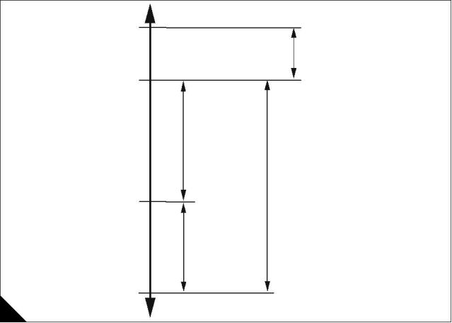
Example: Output voltage from coolant temperature sensor. This diagram is for reference only and should not
be used to diagnose the coolant temperature sensor.
Sensor Diagnostic Generated
(Electronic Problem)
4.8 V
Logged Event, warning,
Engine is too hot,
derate, and shutdown occur
but there is not an
if applicable.
electronic problem
107 °C
4.2 V
(225 °F)
Warm Mode Temperature
Range 20 to 106 °C
(68 to 223 °F)
NORMAL
ENGINE
TEMPERA TURE
RANGE.
63 °C
2.8 V
(145 °F)
Cold Mode Temperature
Range -40 to 20 °C
(-40 to 68 °F)
0.2 V
Sensor Diagnostic Generated
(Electronic Problem)
A
HA0009
Logged events
The ECM can log events. Events refer to engine operating conditions such as low oil pressure or high coolant
temperature. Logged events do not indicate an electronic system problem, but may indicate an engine system
problem. The example diagram shown indicates the output voltage from a coolant temperature sensor and
how the ECM responds to that voltage.
Diagnostic Manual, TSD 3457E, Issue 2
77
This document is printed from SPI². Not for RESALE
![]()
![]()
![]()
4
2300 Series
Diagnostic terminology
Module Identifier (MID) - Two or three digit code which is assigned to each module or control system.
Module ID
Description
024
Engine Control Module (ECM)
Component Identifier (CID) - Two or three digit code which is assigned to each component or system.
Failure Mode Identifier (FMI) - Type of failure the component experienced (adopted from SAE standard
practice J1587 diagnostics).
Failure Mode Identifier
Description
Data valid, but above normal operational range
Data valid, but below normal operational range
Data erratic, intermittent, or incorrect
Voltage above normal or shorted high
Voltage below normal or open circuit
Current below normal or open circuit
Current above normal or grounded circuit
Mechanical system not responding correctly
Abnormal frequency, pulse width, or period
Abnormal update
00
01
02
03
04
05
06
07
08
09
10
Abnormal rate of change
11
Failure mode not identifiable
12
Faulty device or component
13
Uncalibrated device or component
Reserved for future assignment
14 - 31
Active Code - The MID, CID and FMI can be viewed on TIPSS-EST.
Logged Code - The diagnostic will be entered into the permanent memory (Diagnostic Log) when it becomes
Active. The number of occurrences will be saved in the good to bad counter in the permanent memory
(Diagnostic Log). First and last occurrence time (engine hours) will also be saved in the permanent memory
(Diagnostic Log). This information is then available for display on TIPSS-EST.
78
Diagnostic Manual, TSD 3457E, Issue 2
This document is printed from SPI². Not for RESALE
![]()
![]()
![]()
![]()

4
2300 Series
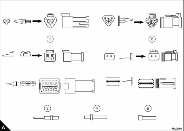
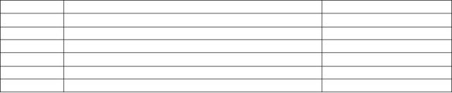
Connectors
Deutsch connectors - These connectors have a plastic housing. The pins and sockets are crimped onto the
electrical wires. The connector has a locking mechanism to hold the pins and sockets. These connectors are
repairable without cutting the wires.
1 Deutsch DT connector receptacles
2 Deutsch DT connector plugs
3 Deutsch and AMP pin
4 Deutsch and AMP socket
5 Deutsch and AMP sealing plug
Diagnostic Manual, TSD 3457E, Issue 2
79
This document is printed from SPI². Not for RESALE
![]()
![]()
![]()
4
2300 Series
Diagnostic code quick reference
CID-FMI
Diagnostic Code Description
Fault finding
1-11
Injector Cylinder #1 Fault
See Test 48 on page 138
See Test 48 on page 138
See Test 48 on page 138
See Test 48 on page 138
See Test 48 on page 138
See Test 48 on page 138
See Test 44 on page 112
See Test 44 on page 112
See Test 44 on page 112
See Test 41 on page 91
See Test 41 on page 91
See Test 41 on page 91
See Test 41 on page 91
See Test 40 on page 88
See Test 41 on page 91
See Test 41 on page 91
See Test 41 on page 91
See Test 41 on page 91
See Test 47 on page 134
See Test 47 on page 134
See Test 47 on page 134
See Test 45 on page 118
2-11
Injector Cylinder #2 Fault
3-11
Injector Cylinder #3 Fault
4-11
Injector Cylinder #4 Fault
5-11
Injector Cylinder #5 Fault
6-11
Injector Cylinder #6 Fault
41-03
8 Volt Sensor Power Supply Open/Short to B+
8 Volt Sensor Power Supply Short to ground
PWM Speed Control Abnormal
41-04
91-08
100-03
100-04
110-03
110-04
168-02
172-03
172-04
174-03
174-04
190-02
190-09
190-11, 12
248-09
Engine Oil Pressure Sensor Open/Short to B+
Engine Oil Pressure Sensor Short to ground
Engine Coolant Temp Sensor Open/Short to B+
Engine Coolant Temp Sensor Short to ground
Intermittent Battery Power to the ECM
Intake Manifold Temperature Sensor Open/Short to B+
Intake Manifold Temperature Sensor Short to ground
Fuel Temperature Sensor Open/Short to B+
Fuel Temperature Sensor Short to ground
Engine Speed Sensor Data Intermittent
Engine Speed Sensor Abnormal Update
Engine Speed Sensor Mechanical Fault
Perkins Data Link Communications Abnormal
See "System configuration
parameters" on page 12
253-02
254-12
Check Customer or System Parameters
ECM Fault
See "Programming a new ECM"
on page 24
261-13
262-03
262-04
Engine Timing Calibration Required
See Test 47 on page 134
See Test 43 on page 107
See Test 43 on page 107
5 Volt Sensor Power Supply Open/Short to B+
5 Volt Sensor Power Supply Short to ground
See "Programmable
parameters" on page 12
268-02
Check Programmable Parameters
273-03
273-04
274-03
274-04
281-05
281-06
282-03
282-04
285-03
285-04
286-03
286-04
323-05
323-06
324-05
324-06
342-02
342-11, 12
Turbo Outlet Pressure Sensor Open/Short to B+
Turbo Outlet Pressure Sensor Short to ground
Atmospheric Pressure Sensor Open/Short to B+
Atmospheric Pressure Sensor Short to ground
Action Alert Lamp Open Circuit
See Test 41 on page 91
See Test 41 on page 91
See Test 41 on page 91
See Test 41 on page 91
See Test 42 on page 101
See Test 42 on page 101
See Test 42 on page 101
See Test 42 on page 101
See Test 42 on page 101
See Test 42 on page 101
See Test 42 on page 101
See Test 42 on page 101
See Test 42 on page 101
See Test 42 on page 101
See Test 42 on page 101
See Test 42 on page 101
See Test 46 on page 126
See Test 46 on page 126
Action Alert lamp Short to ground
Engine Overspeed lamp Open/Short to B+
Engine Overspeed lamp Short to ground
Engine Coolant temperature lamp Open/Short to B+
Engine Coolant temperature lamp Short to ground
Engine Lubricating oil pressure lamp Open/Short to B+
Engine Lubricating oil pressure lamp Short to ground
Engine Shutdown Lamp Open Circuit
Engine Shutdown lamp Short to ground
Engine Warning Lamp Open Circuit
Engine Warning lamp Short to ground
Engine Speed Sensor No. 2 Data Intermittent
Engine Speed Sensor No. 2 Mechanical Fault
80
Diagnostic Manual, TSD 3457E, Issue 2
This document is printed from SPI². Not for RESALE
![]()
![]()
![]()

4
2300 Series
CID-FMI
443-05
Diagnostic Code Description
Fault finding
See Test 42 on page 101
See Test 42 on page 101
Contact Help Desk
Crank Terminate Relay Open Circuit
443-06
Crank Terminate Relay Short to ground
Service Tool Fault
799-12
1266-03
1266-04
1690-8
Diagnostic lamp Open/Short to B+
Diagnostic lamp Short to ground
Analogue Throttle Signal Abnormal
See Test 42 on page 101
See Test 42 on page 101
See Test 49 on page 146
Diagnostic Manual, TSD 3457E, Issue 2
81
This document is printed from SPI². Not for RESALE
![]()
![]()
![]()
4
2300 Series
Diagnostic tests
Inspecting electrical connectors
Test 39
Functional test
System operation
Many of the diagnostic tests in this manual will direct you to check a specific electrical connector.
Use this test to thoroughly inspect the connectors and determine if they are the cause of a fault. If a problem
is found in an electrical connector, repair the connector and check that the fault has been corrected.
Intermittent electrical faults are often caused by poor connections. Always check for an active diagnostic code
before breaking any connections and check again immediately after reconnecting the connector to see if the
fault has been corrected. Simply disconnecting and then reconnecting connectors can sometimes correct a
fault. If this occurs, likely causes are loose terminals, bent terminals, incorrectly crimped terminals or corrosion.
ECM terminal connections (general layout)
ECM AMP Connectors
17
2
3
4
5
6
8
9
10 11 12
13
23
31
39
47
57
70
13
12 11 10
9
8
7
6
5
4
3
2
1
14 15 16 17 18
24 25 26 27
>PEI<
19 20 21 22
28 29 30
23 22 21 20 19
31 30 29 28
39 38 37 36
47 46 45 44
18 17 16 15
27 26 25
14
24
32
40
48
32 33 34 35
36 37 38
35 34 33
40 41 42 43
44 45 46
43
51
42
50
41
49
48 49 50 51 52
53 54 55 56
57 56 55 54 53
52
58 59 60 61 62 63 64 65 66 67 68 69
70 69 68 67 66 65 64 63 62 61 60 59
58
ECM Side
Harness Side
Harness Connector P1
13
12 11 10
9
8
7
6
5
4
3
2
1
17
2
3
4
5
6
8
9
10 11 12
13
23
31
39
47
57
70
23 22 21 20 19
31 30 29 28
39 38 37 36
47 46 45 44
18 17 16 15
27 26 25
14
24
32
40
48
14 15 16 17 18
24 25 26 27
>PEI<
19 20 21 22
28 29 30
35 34 33
32 33 34 35
36 37 38
43
51
42
50
41
49
40 41 42 43
44 45 46
57 56 55 54 53
52
48 49 50 51 52
53 54 55 56
70 69 68 67 66 65 64 63 62 61 60 59
58
58 59 60 61 62 63 64 65 66 67 68 69
ECM Side
Harness Side
Harness Connector P2
A
HA0011
82
Diagnostic Manual, TSD 3457E, Issue 2
This document is printed from SPI². Not for RESALE
![]()
![]()
![]()
![]()
![]()
![]()
4
2300 Series
Functional test
Test 39 - Inspecting electrical connectors
Test step
Result
Action
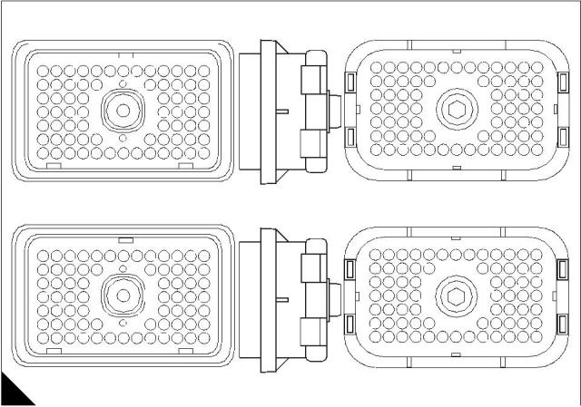
Step 1: Check the connector mating
Ensure that the plug and receptacle are correctly locked
together and cannot be pulled apart.
Go to step 2.
Repair or renew as
necessary.
Check that the connector locking tab is correctly locked and
returns to the fully locked position.
STOP.
Check that the connector and the locking mechanism is not
damaged.
Check that the connector interface is free from dirt and dust.
The connector will securely lock. The connector and locking
mechanism is without cracks or breaks.
Step 2: Check the ECM connector Allen screw
Ensure the Allen screw is correctly tightened to not more than
3,0 Nm (2.2 lb ft) 0,31 kgf m when mating the 70-terminal
“AMP” connector to the ECM.
Go to step 3.
Repair or renew as
necessary.
The ECM connector is secure and the ECM connector bolt is
correctly torqued.
STOP.
Step 3: Perform a 45 N (10 lb) pull test on each terminal and wire
Each terminal and connector should easily withstand 45 N
(10 lb) of pull and remain in the connector body. This test
checks if the wire is crimped correctly in the terminal and if the
terminal was correctly inserted into the connector.
Go to step 4.
Repair or renew as
necessary.
STOP.
Note: Terminals should always be crimped onto the wires using an
appropriate tool. Do not solder terminals.
Each terminal and connector easily withstands 45 N (10 lb) of
pull, and remains in the connector body.
Step 4: Observe the effect of the pull test on the electronic service tool
Warning! There is a strong electrical shock hazard while the
engine is turning. Do not touch wires associated with the injector
circuit while the engine is cranking or running.
Go to step 5.
Repair or renew as
necessary.
If there is an active diagnostic code pertaining to the circuit:
STOP.
Monitor the TIPSS-EST "Active Code" screen while pulling
on all harnesses and connectors that connect to the
component with the active diagnostic code. If the active
diagnostic code disappears while pulling on the harness,
there is a problem in the wiring or connector.
If there are no active diagnostic codes:
Monitor the TIPSS-EST "Status" screen for the component
while pulling on the harnesses. If the reading changes
erratically while pulling, there is a problem in the wiring or
connector.
If there are no active diagnostic codes and there is a sudden
intermittent engine speed changes or misfire:
Run the engine and listen for engine speed changes or
misfire while pulling on the wiring or connectors. If the
engine speed changes or cuts out while pulling on the
harness, there is a problem in the wiring or connector.
The problem appears to be external to the harnesses and
connectors. Tugging on the harnesses and connectors has no
affect on the active diagnostic code, component status, or
engine performance.
Diagnostic Manual, TSD 3457E, Issue 2
83
This document is printed from SPI². Not for RESALE
![]()
![]()
![]()
![]()
![]()
![]()
![]()
![]()
![]()
![]()
![]()
![]()
![]()
![]()
![]()
![]()
![]()
![]()
![]()
![]()
![]()
![]()
![]()

4
2300 Series
Test 39 - Inspecting electrical connectors (Continued)
Test step
Result
Action
Step 5: Check wires for damage to the insulation
Carefully inspect each wire for signs of abrasion or cuts. Likely
locations to check are anywhere the insulation is exposed,
points where the wire rubs against the engine or a sharp point.
Go to step 6.
Repair or renew as
necessary.
Check all harness clamps to ensure the harness is correctly
fitted and the clamp is not compressing the harness. Pull the
harness sleeves away to check for flattened wires where the
clamp holds the harness.
STOP.
The wires are free of abrasion or cuts and the harness is
correctly clamped.
Step 6: Check connectors for moisture or corrosion
Ensure the connector seals and the white sealing plugs are in
place. Refer to "Sealing plug insertion" on page 87. If any of the
seals or plugs are missing, renew the seal, plug, or if
necessary, the connector.
Go to step 7.
Repair or renew wiring or
connectors as necessary.
Ensure all seals are correctly
installed and that connectors
are completely mated.
Check all wiring harnesses to ensure that the harness does not
make a sharp bend out of a connector. Refer to "Harness
routing" on page 86. This will deform the connector seal and
create a moisture entry path.
Check that the repair
eliminates the fault by
running the engine for
several minutes and check
again for moisture.
Thoroughly inspect the ECM connectors J1/P1 and J2/P2 for
evidence of moisture entry.
Note: It is normal to see some minor seal abrasion on the ECM
connector seals. Minor seal abrasion will not allow moisture entry.
If moisture reappears, it is
wicking into the connector.
Even if the moisture entry
path is repaired, it may be
necessary to renew the
If moisture or corrosion is evident in the connector, the source
of the moisture entry must be found and repaired or the fault will
occur again. Simply drying the connector will not correct the
fault. Likely moisture entry paths are:
wires that have moisture
wicking through them as the
wires may have moisture
trapped inside the insulation.
Missing or incorrectly fitted seals
Cuts in the insulation
Unmated connectors.
Moisture can also travel or “wick” from one connector through
the inside of a wire to the ECM connector. If moisture is found
in the ECM connector, thoroughly check all connectors and
wires on the harness that connect to the ECM.
Check that the repair
eliminates the fault.
STOP.
Note: The ECM is not the source of the moisture. Do not renew an
ECM if moisture is found in either ECM connector.
Caution: If corrosion is evident on pins, sockets or the connector
itself, use only denatured alcohol to clean/remove the corrosion
with a cotton swab or a soft brush. Do not use any cleaners that
contain 1,1,1 trichloro-ethylene because it may damage the
connector.
All connectors/seals are completely mated/inserted, and the
harness/wiring is free of corrosion, abrasion or pinch points.
Step 7: Inspect the connector terminals
Check that the terminals are not damaged. Check for correct
alignment and location of terminals in the connector.
Go to step 8.
Repair or renew as
necessary.
The terminals are correctly aligned and appear undamaged.
STOP.
84
Diagnostic Manual, TSD 3457E, Issue 2
This document is printed from SPI². Not for RESALE
![]()
![]()
![]()
![]()
![]()
![]()
![]()
![]()
![]()
![]()
![]()
![]()
![]()
![]()
![]()
![]()
![]()
![]()
![]()
![]()

4
2300 Series
Test 39 - Inspecting electrical connectors (Continued)
Test step
Result
Action
Step 8: Check individual pin retention into the socket
Note: This is especially important for intermittent faults.
STOP.
Insert a new pin into a socket of the female connector to check
for a good grip on the pin by the socket. Repeat this test with
the same pin in each socket of the connector.
Repair or renew as
necessary.
STOP.
Repeat the test for each pin on the male side of the connector,
by use of a new socket on each pin. The terminal contact (pin
or socket) should stay in place when the connector is held
upside down.
The pins and sockets appear to be in good condition.
Diagnostic Manual, TSD 3457E, Issue 2
85
This document is printed from SPI². Not for RESALE
![]()
![]()
![]()
![]()
![]()
![]()
![]()

4
2300 Series
Harness routing
B
HA0012
86
Diagnostic Manual, TSD 3457E, Issue 2
This document is printed from SPI². Not for RESALE
![]()
![]()
![]()
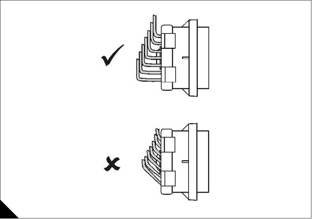
4
2300 Series
Sealing plug insertion
C
HA0013
Diagnostic Manual, TSD 3457E, Issue 2
87
This document is printed from SPI². Not for RESALE
![]()
![]()
![]()
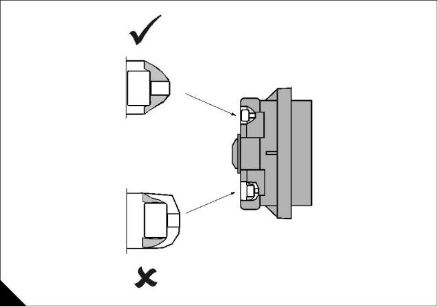
4
2300 Series
Electrical power supply to the ECM
Test 40
Diagnostic codes
Functional test
System operation
This procedure tests if the correct voltage is supplied to the ECM by the equipment wiring. Use this procedure
if a 168-02 Intermittent Battery Power to the ECM diagnostic codes is logged, or if you suspect the ECM is not
receiving battery supply voltage.
The ECM input at connector P1 terminal-70 (SWITCHED +BATTERY) receives battery voltage from the
engine key switch supplied by the OEM. When the ECM detects battery voltage at this input, the ECM will
power up.
When battery voltage is removed from this input, the ECM will power down after the engine has safely shut
down.
The cause of an intermittent power supply to the ECM can occur on either the positive (UNSWITCHED
+BATTERY) or negative (-BATTERY) side. Both sides are routed from the ECM to the battery.
The three Unswitched +Battery connections should be routed through a dedicated protection circuit.
ECM electrical power supply schematic
Note: Refer to the wiring diagram for full connection details. This wiring is supplied by the OEM.
J1
ECM
61
63
65
- Battery
- Battery
- Battery
Emergency
Stop Button
48
52
53
Unswitched + Battery
Unswitched + Battery
Unswitched + Battery
70
Switched + Battery
Circuit
Breaker
Key
Switch
Start
Button
Starter
Motor
-
+
Battery
24V DC
A
HA0014
88
Diagnostic Manual, TSD 3457E, Issue 2
This document is printed from SPI². Not for RESALE
![]()
![]()
![]()
![]()
![]()
![]()
![]()
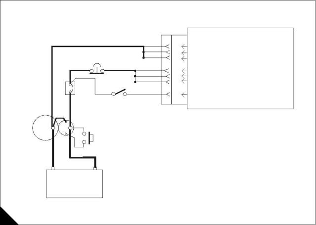
4
2300 Series
Diagnostic codes
Diagnostic
fault code
Conditions that could cause the code
System response
To find the fault
168-02
Intermittent Battery Power to the ECM
Engine response
Proceed with Test
40: Electrical power
supply to the ECM.
Indicates the battery circuit to the ECM has
either an intermittent or low battery condition
while the engine is running.
The engine may experience
intermittent engine speed
changes, intermittent and/or
complete engine shutdowns while
the conditions causing this
diagnostic code are present.
If battery voltage disappears without
returning, the ECM will not log this diagnostic
code and the engine will shut down.
Functional test
Test 40 - Electrical power supply to the ECM
Test step
Result
Action
Step 1: Inspect electrical connectors and wiring
Thoroughly inspect the ECM harness connector J1/P1, the
breaker and battery connections, and the connections to the
engine key switch. Refer to Test 39: Inspecting electrical
connectors on page 82 for details.
Go to step 2.
Repair or renew wiring or
connectors as necessary.
Check all seals are correctly
installed and that connectors
are completely mated.
Check the emergency stop switch.
Perform a 45 N (10 lb) pull test on each of the wires in the ECM
connector associated with the Unswitched +Battery
(terminal-52, 53 and 48), -Battery (terminal-63, 65 and 61), and
Switched +Battery (terminal-70) connections. Refer to "ECM
Terminal connections" on page 90.
Check that the repair
eliminates the fault.
STOP.
Check that the ECM connector Allen screw is correctly
tightened to not more than 3,0 Nm (2.2 lb ft) 0,31 kgf m.
Check the harness and wiring for abrasion and pinch points
from the battery to the ECM, and from the key switch to the
ECM.
All connectors/pins/sockets are completely mated/inserted,
and the harness/wiring is free of corrosion, abrasion or pinch
points.
Step 2: Check battery input voltage at the ECM
Turn the key switch to the ON position.
The ECM is currently
receiving the correct
voltage.
Measure the voltage at the battery post terminals. If the voltage
is not between 24.8 and 29 Volts DC, diagnose the charging
system.
If the fault is intermittent
refer to Test 39: Inspecting
electrical connectors on
page 82.
Note: If using a power supply instead of batteries, the minimum
requirement is 22 Volts DC at 16 Amps.
Measure the voltage between P1 terminal-52 (UNSWITCHED
+BATTERY) and P1 terminal-63 (-BATTERY). Refer to "ECM
Terminal connections" on page 90.
STOP.
The correct voltages do not
appear at P1.
The voltage measurements at P1 are constant and within
2 Volts DC of the voltage measured at the battery post
terminals.
Check for breakers and/or
an emergency stop switch.
Check through the wiring
with a voltmeter to find the
source of the voltage drop.
Refer to the "ECM electrical
power supply schematic" on
page 88.
Repair as required.
STOP.
Diagnostic Manual, TSD 3457E, Issue 2
89
This document is printed from SPI². Not for RESALE
![]()
![]()
![]()

![]()
![]()
![]()
![]()
![]()
![]()
![]()
![]()
![]()
![]()
![]()
![]()

4
2300 Series
ECM Terminal connections
Note: Using ECM connector P1.
13
12 11 10
9
8
7
6
5
4
3
2
1
Function
Unswitched + Battery
Unswitched + Battery
Unswitched + Battery
Switched + Battery
- Battery
Pin Location
23 22 21 20 19
31 30 29 28
39 38 37 36
47 46 45 44
18 17 16 15
27 26 25
14
24
32
40
48
48
52
53
70
61
63
65
35 34 33
43 42 41
57 56 55 54 53
52 51
50 49
70 69 68 67 66 65 64 63 62 61 60 59
58
- Battery
- Battery
Terminal side
70 69 68 67 66 65 64 63 62 61 60 59
58
57
47
48
40
36
31
23
24
14
>PEI<
13 12 11 10
9
8
7
6
5
4
3
2
1
Wire side
B
HA0015
90
Diagnostic Manual, TSD 3457E, Issue 2
This document is printed from SPI². Not for RESALE
![]()
![]()
![]()
![]()
![]()
![]()
![]()
![]()
![]()
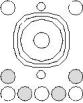
![]()
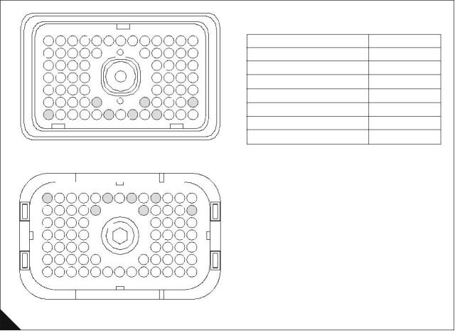
4
2300 Series
Analogue sensor open or short circuit test
Test 41
Diagnostic codes
Functional test
System operation
Use this procedure to diagnose open or short circuit diagnostic codes for the oil pressure sensor, atmospheric
pressure sensor, turbo outlet pressure sensor, fuel temperature sensor, engine coolant temperature sensor,
and intake manifold temperature sensor.
Note: The engine coolant temperature sensor, fuel temperature sensor and intake manifold temperature
sensor do not require +5 V supply voltage from the ECM.
The diagnostic procedures for each sensor open and short circuit diagnostic code are identical.
The ECM provides supply voltage from ECM connector J2/P2 terminal-2 (+5 V Supply) to the sensor connector
terminal-A. The sensor return (ground) connection is also shared, provided from ECM connector J2/P2
terminal-3 (analogue return) to each sensor connector terminal-B. The signal voltage from each sensor is
supplied from the sensor connector terminal-C to the appropriate sensor signal terminal at ECM connector J2/
P2. Refer to the "Analogue sensor schematic" on page 92 for further details.
Diagnostic Manual, TSD 3457E, Issue 2
91
This document is printed from SPI². Not for RESALE
![]()
![]()
![]()
![]()
![]()
![]()
![]()
4
2300 Series
Analogue sensor schematic
Note: Refer to the wiring diagram for full connection details.
Atmospheric Pressure Sensor
A
C
B
J2/2
J2/14
J2/3
+5VDC Supply
Atmospheric Pressure
Analogue Return
+5V
Signal
Return
ECM
Turbo Outlet Pressure Sensor
+5V
Signal
Return
A
C
B
J2/40
Turbo Outlet Pressure
Oil Pressure Sensor
A
C
B
+5V
Signal
Return
J2/24
J2/32
J2/33
Oil Pressure
Coolant Temperature Sensor
Coolant Temperature
Signal
Return
C
B
Fuel Temperature Sensor
Fuel Temperature
Signal
Return
C
B
Intake Manifold Temperature Sensor
Signal
Return
C
B
J2/35
J2/18
Intake Manifold Temperature
Return
A
HA0016
92
Diagnostic Manual, TSD 3457E, Issue 2
This document is printed from SPI². Not for RESALE
![]()
![]()
![]()
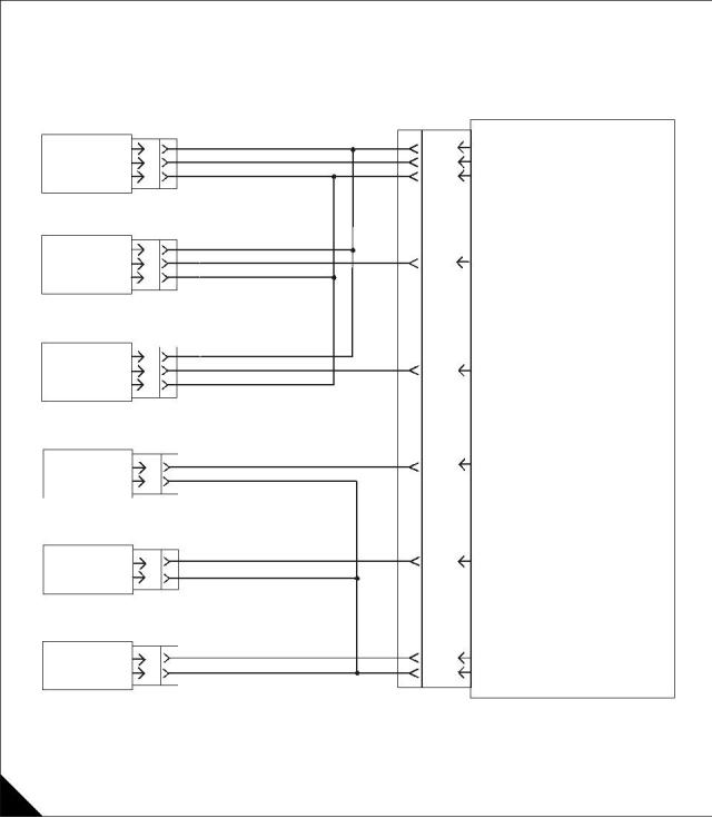
4
2300 Series
Diagnostic codes
Diagnostic
fault code
Conditions that could cause the code
System response
To find the fault
100-03
Oil Pressure Sensor Open Or Shorted
High
The ECM assumes a default
filtered oil pressure and engine
protection monitoring for low or
Proceed with Test
41: Analogue
sensor open or
The oil pressure sensor signal input to the
ECM is greater than 4.8 Volts DC, indicating
an open circuit or short to a positive voltage
source
excessive oil pressure is disabled. short circuit test.
This diagnostic code remains
active until the engine control
switch is turned to the OFF
position.
AND
A +5 V Sensor Supply diagnostic code
(262-03 or 262-04) is NOT active.
Note: Since engine protection is
no longer available, the engine is
shut down.
100-04
Oil Pressure Sensor Short To Ground
The ECM assumes a default
filtered oil pressure and engine
protection monitoring for low or
Proceed with Test
41: Analogue
sensor open or
The oil pressure sensor signal input to the
ECM is less than 0.2 Volts DC, indicating a
short to ground
excessive oil pressure is disabled. short circuit test.
This diagnostic code remains
active until the engine control
switch is turned to the OFF
position.
AND
A +5 V Sensor Supply diagnostic code
(262-03 or 262-04) is NOT active.
Note: Since engine protection is
no longer available, the engine is
shut down.
110-03
Coolant Temperature Sensor Open
The ECM assumes a default
coolant temperature and engine
protection monitoring for low or
excessive coolant temperature is
disabled.
Proceed with Test
41: Analogue
sensor open or
short circuit test.
The coolant temperature sensor signal input
to the ECM is above acceptable range,
indicating an open circuit or short to a positive
voltage source.
This diagnostic code remains
active until the engine control
switch is turned to the OFF
position.
Note: Since engine protection is
no longer available, the engine is
shut down.
110-04
Coolant Temperature Sensor Short to
Ground
The ECM assumes a default
coolant temperature. Engine
protection monitoring for low or
excessive coolant temperature is
disabled.
Proceed with Test
41: Analogue
sensor open or
short circuit test.
The coolant temperature sensor signal input
to the ECM is below acceptable range,
indicating a short to ground.
This diagnostic code remains
active until the engine control
switch is turned to the OFF
position.
Note: Since engine protection is
no longer available, the engine is
shut down.
Diagnostic Manual, TSD 3457E, Issue 2
93
This document is printed from SPI². Not for RESALE
![]()
![]()
![]()

4
2300 Series
Diagnostic
fault code
Conditions that could cause the code
System response
To find the fault
172-03
Intake Manifold Temperature Sensor Open
The ECM assumes a default
intake manifold temperature.
Proceed with Test
41: Analogue
sensor open or
short circuit test.
The intake manifold temperature sensor
signal input to the ECM is greater than 4.8
Volts DC, indicating an open circuit or short to excessive inlet manifold
Engine protection monitoring for
a positive voltage source.
temperature is disabled and the
air-fuel ratio control no longer
compensates for manifold
temperature.
Engine performance may be
affected.
172-04
Intake Manifold Temperature Sensor Short The ECM assumes a default
Proceed with Test
41: Analogue
To Ground
intake manifold temperature.
sensor open or
short circuit test.
The intake manifold temperature sensor
signal input to the ECM is less than 0.2 Volts excessive inlet manifold
Engine protection monitoring for
DC, indicating a short to ground.
temperature is disabled and the
air-fuel ratio control no longer
compensates for manifold
temperature.
Engine performance may be
affected.
174-03
174-04
273-03
Fuel Temperature Sensor Open
The ECM assumes a default fuel
temperature. Engine protection
monitoring for high fuel
Proceed with Test
41: Analogue
sensor open or
short circuit test on
page 91
The fuel temperature sensor signal input to
the ECM is greater than 4.8 Volts DC,
indicating an open circuit or short to a positive
voltage source.
temperature is disabled.
This diagnostic code remains
active until the engine control
switch is turned to the OFF
position.
Fuel Temperature Sensor Short To
Ground
The ECM assumes a default fuel
temperature. Engine protection
monitoring for high fuel
Proceed with Test
41: Analogue
sensor open or
short circuit test on
page 91
The fuel temperature sensor signal input to
the ECM is less than 0.2 Volts DC, indicating
a short to ground.
temperature is disabled.
This diagnostic code remains
active until the engine control
switch is turned to the OFF
position.
Intake Manifold Pressure Sensor Open
The ECM assumes a default
pressure and engine protection
monitoring for boost pressure is
disabled.
Proceed with Test
41: Analogue
sensor open or
short circuit test.
The turbo outlet pressure sensor signal input
to the ECM is greater than 4.8 Volts DC,
indicating an open circuit or short to a positive
voltage source
Engine performance may be
affected.
AND
A +5 V Sensor Supply diagnostic code
(262-03 or 262-04) is NOT active.
273-04
Intake Manifold Pressure Sensor Short To The ECM assumes a default
Proceed with Test
41: Analogue
sensor open or
short circuit test.
Ground
pressure and engine protection
monitoring for boost pressure is
disabled.
The intake manifold pressure sensor signal
input to the ECM is less than 0.2 Volts DC,
indicating a short to ground
Engine performance may be
affected.
AND
A +5 V Sensor Supply diagnostic code
(262-03 or 262-04) is NOT active.
94
Diagnostic Manual, TSD 3457E, Issue 2
This document is printed from SPI². Not for RESALE
![]()
![]()
![]()

4
2300 Series
Diagnostic
fault code
Conditions that could cause the code
Atmospheric Pressure Sensor Open
System response
To find the fault
274-03
The ECM assumes a default
pressure. Engine power may be
de-rated.
Proceed with Test
41: Analogue
sensor open or
short circuit test.
The atmospheric pressure sensor signal input
to the ECM is greater than 4.8 Volts DC,
indicating an open circuit or short to a positive Note: Since engine protection is
voltage source
no longer available, the engine is
shut down.
AND
A +5 V Sensor Supply diagnostic code
(262-03 or 262-04) is NOT active.
If the Atmospheric Pressure
Sensor is faulty, the Oil Pressure
and Intake Manifold pressure
sensors will display 'Abnormal/
Incorrect Data' on TIPSS/EST.
274-04
Atmospheric Pressure Sensor Short To
Ground
The ECM assumes a default
pressure. Engine power may be
de-rated.
Proceed with Test
41: Analogue
sensor open or
short circuit test.
The atmospheric pressure sensor signal input
to the ECM is less than 0.2 Volts DC,
indicating a short to ground
Note: Since engine protection is
no longer available, the engine is
shut down.
AND
A +5 V Sensor Supply diagnostic code
(262-03 or 262-04) is NOT active.
If the Atmospheric Pressure
Sensor is faulty, the Oil Pressure
and Intake Manifold pressure
sensors will display 'Abnormal/
Incorrect Data' on TIPSS/EST.
Diagnostic Manual, TSD 3457E, Issue 2
95
This document is printed from SPI². Not for RESALE
![]()
![]()
![]()