English
 Espaol
 Franais
 阿拉伯
阿拉伯 中文
中文 Deutsch
 Italiano
 Português
 日本
日本 韩国
韩国 български
 hrvatski
 esky
esky Dansk
Dansk Nederlands
 suomi
suomi Ελληνικ
 印度
印度 norsk
norsk Polski
 Roman
Roman русский
 Svenska
Perkins2306A(C)-E14车间手册供应商,Perkins2306A(C)-E14车间手册技术价格规格咨询服务,Perkins2306A(C)-E14车间手册零配件供应,Perkins2306A(C)-E14车间手册售后服务中心,Perkins2306A(C)-E14车间手册,Perkins2306A(C)-E14车间手册详细的技术参数,

产品中心
Perkins2306A(C)-E14车间手册
详细描述
Perkins 2300 Series
Models 2306A-E14 and 2306C-E14
WORKSHOP MANUAL
6 cylinder turbocharged diesel engines for industrial
applications
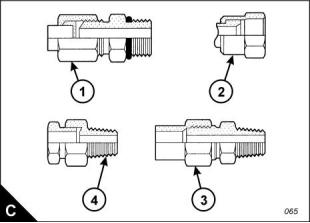
Torque figures for flared and ‘O’ ring fittings
The torque figures given in the table below and the table given on page 17 should be applied to the nut of the
fittings which follow: 37 degree flared fittings (C1), 45 degree flared fittings (C3), inverted flared fittings (C2),
‘O’ ring fittings for a recessed drive, ‘O’ ring fittings for air conditioning and swivel nuts (C2). The figures should
be used for applications which allow these working pressures: 7750 to 34450 kPa (1125 to 5000 lb/in²). The
torque figure depends on the size and type of fitting.
Nuts for 37 degree flared fittings
Thread size
Inches
Standard
torque
Outside diameter of nominal tube
3,18 mm
(0.125 in)
5,0 +/- 1,5 Nm
(4 +/- 1 lbf ft)
5/16
3/8
4,76 mm
(0.188 in)
11 +/- 2 Nm
(8 +/- 1 lbf ft)
6,35 mm
(0.250 in)
16 +/- 4 Nm
(12 +/- 3 lbf ft)
7/16
1/2
7,94 mm
(0.312 in)
20 +/- 5 Nm
(15 +/- 4 lbf ft)
9,52 mm
(0.375 in)
25 +/- 5 Nm
(18 +/- 4 lbf ft)
9/16
5/8
9,52 mm
(0.375 in)
35 +/- 5 Nm
(26 +/- 4 lbf ft)
12,70 mm
(0.500 in)
50 +/- 7 Nm
(37 +/- 5 lbf ft)
3/4
15,88 mm
(0.625 in)
65 +/- 7 Nm
(48 +/- 5 lbf ft)
7/8
19,05 mm
(0.750 in)
100 +/- 10 Nm
(75 +/- 7 lbf ft)
1 1/16
1 3/16
1 5/16
1 5/8
1 7/8
2 1/2
22,22 mm
(0.875 in)
120 +/- 10 Nm
(90 +/- 7 lbf ft)
25,40 mm
(1.000 in)
135 +/- 15 Nm
(100 +/- 11 lbf ft)
31,75 mm
(1.250 in)
180 +/- 15 Nm
(135 +/- 11 lbf ft)
38,10 mm
(1.500 in)
225 +/- 15 Nm
(165 +/- 11 lbf ft)
50,80 mm
(2.000 in)
320 +/- 30 Nm
(240 +/- 22 lbf ft)
Note: For the table above, use 50 percent of the torque figure when the fitting, the plug or the port material is
nonferrous.
24
Workshop Manual, TSD3455E, Issue 2
This document is printed from SPI². Not for RESALE
![]()
![]()

2
2300
45 degree flared and 45 degree inverted flare fittings
45 degree flared and 45 degree inverted flare fittings
Thread size
Standard
torque
Outside diameter of nominal tube
Inches
3,18 mm
(0.125 in)
5,0 +/- 1,5 Nm
(4 +/- 1 lbf ft)
5/16
3/8
7/16
1/2
5/8
4,76 mm
(0.188 in)
8 +/- 1,5 Nm
(6 +/- 1 lbf ft)
6,35 mm
(0.250 in)
11 +/- 2 Nm
(8 +/- 1 lbf ft)
7,94 mm
(0.312 in)
17 +/- 3 Nm
(13 +/- 2 lbf ft)
9,52 mm
(0.375 in)
30 +/- 3 Nm
(22 +/- 2 lbf ft)
11,11 mm
11/16
30 +/- 3 Nm
(22 +/- 2 lbf ft)
(0.438 in)
12,70 mm
(0.500 in)
38 +/- 4 Nm
(28 +/- 3 lbf ft)
3/4
7/8
15,88 mm
(0.625 in)
50 +/- 5 Nm
(37 +/- 4 lbf ft)
19,05 mm
1 1/16
90 +/- 8 Nm
(65 +/- 6 lbf ft)
(0.750 in)
22,22 mm
(0.875 in)
100 +/- 10 Nm
(75 +/- 7 lbf ft)
1 1/4
Tapered pipe thread fittings
Tapered pipe thread fittings
Standard torque
Thread size
Inches
Threads with pipe sealant
Threads without pipe sealant
(CV60891)
1/16 - 27
1/8 - 27
10 Nm (7 lbf ft)
16 Nm (12 lbf ft)
20 Nm (15 lbf ft)
35 Nm (26 lbf ft)
45 Nm (33 lbf ft)
60 Nm (44 lbf ft)
75 Nm (55 lbf ft)
90 Nm (65 lbf ft)
110 Nm (80 lbf ft)
130 Nm (95 lbf ft)
10 Nm (7 lbf ft)
16 Nm (12 lbf ft)
25 Nm (18 lbf ft)
45 Nm (33 lbf ft)
60 Nm (44 lbf ft)
75 Nm (55 lbf ft)
90 Nm (65 lbf ft)
110 Nm (80 lbf ft)
130 Nm (95 lbf ft)
160 Nm (120 lbf ft)
1/4 - 18
3/8 - 18
1/2 - 14
3/4 - 14
1 - 11 1/2
1 1/4 - 11 1/2
1 1/2 - 11 1/2
2 - 11 1/2
Note: For the table above, use 50 percent of the torque figure when the fitting, the plug or the port material is
nonferrous.
Workshop Manual, TSD3455E, Issue 2
25
This document is printed from SPI². Not for RESALE
![]()
![]()


2
2300
Torque figures for standard hose clamps of the worm drive band type
Torque figure for initial
installation on a new hose
Width of clamp
7,9 mm (0.31 in)
13,5 mm (0.53 in)
15,9 mm (0.63 in)
Width of clamp
0,9 +/- 0,2 Nm (8 +/- 2 lbf in)
4,5 +/- 0,5 Nm (40 +/- 4 lbf in)
7,5 +/- 0,5 Nm (65 +/- 4 lbf in)
Torque figure for used clamp
0,7 +/- 0,2 Nm (6 +/- 2 lbf in)
3,0 +/- 0,5 Nm (27 +/- 4 lbf in)
4,5 +/- 0,5 Nm (40 +/- 4 lbf in)
7,9 mm (0.31 in)
13,5 mm (0.53 in)
15,9 mm (0.63 in)
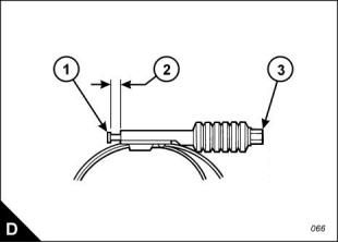
Torque figures for constant torque hose clamps
Use a torque wrench for the correct installation of a constant torque hose clamp. For a constant torque hose
clamp to be installed correctly, these conditions must exist:
The screw tip (D1) must extend by 6,35 mm (0.250 in) beyond the housing (D2).
The belleville washers must be collapsed almost flat after the screw (D3) has been tightened to a torque of
11 +/- 1 Nm (98 +/- 9 lb in).
26
Workshop Manual, TSD3455E, Issue 2
This document is printed from SPI². Not for RESALE
![]()
![]()

2300
3
Cylinder head assembly
3
General information
The cylinder head is a single-piece cast iron component. The camshaft is mounted in the cylinder head and
runs in shell bearings. The bearings are pressed into each journal and are lubricated under pressure. Bridge
piece guides have been eliminated as floating valve bridges have been utilised.
Special thermal sleeves manufactured from stainless steel are fitted to the exhaust ports. These reduce the
amount of heat transferred to the cooling system and direct the thermal energy to the turbocharger.
The electronic unit injectors are mounted in stainless steel sleeves which have been pressed into the injector
bores of the cylinder head.
The operations to remove and to fit valve seat inserts and to remove and to fit camshaft bearings are not
included as specialist equipment is required. It is recommended that operators take advantage of the Perkins
service exchange scheme if these procedures become necessary.
Workshop Manual, TSD3455E, Issue 2
27
This document is printed from SPI². Not for RESALE
![]()
![]()
3
2300
Rocker cover
To remove and to fit
Operation 3-1
To remove
Warning! The electrical circuit for the fuel injector units operates on 110 volts. Do NOT work on the fuel injector
units unless the power supply to the ECM has been disconnected.
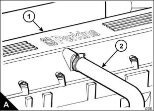
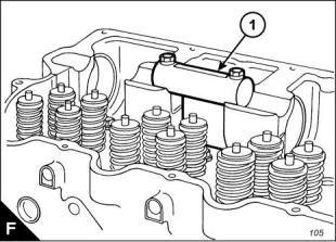
1 Disconnect the wiring harness at the socket on the rocker cover (A1).
2 Disconnect and remove the engine breather pipe (A2).
3 Loosen fully the bolts which retain the rocker cover, but do not remove the bolts from the assembly; allow
them to be retained by the seal.
4 Remove the rocker cover.
To fit
1 Inspect the seal of the rocker cover and renew if worn of damaged.
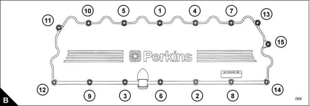
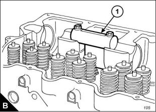
2 Fit the rocker cover, complete with seal and bolts. Tighten the bolts to a torque of 20 Nm (15 lbf ft); use the
sequence shown (B).
3 Fit the engine breather pipe (A2).
4 Connect the wiring harness. Ensure that the wiring harness is fully engaged with the connector.
28
Workshop Manual, TSD3455E, Issue 2
This document is printed from SPI². Not for RESALE
![]()
![]()
![]()
![]()
3
2300
Rocker lever and rocker shaft assemblies
To remove and to fit
Operation 3-2
To remove
1 Remove the rocker cover, Operation 3-1.
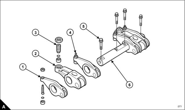
2 The valve rocker levers (A1) and the unit injector rocker levers (A2) can move on the shaft (A6) after the four
bolts (A5) have been removed. The shaft (A6) should be kept level when removed from the cylinder head. To
avoid possible personal injury, keep fingers clear of the rocker levers (A1 and A2) during removal of the
assembly from the cylinder head.
3 Remove the four bolts (A5).
4 Remove the shaft (A6), valve rocker levers (A1) and unit injector rocker levers (A2) as a unit.
5 Repeat steps 1 and 2 for the rocker shaft assemblies which remain.
To fit
1 Loosen the adjustment screws (A3 and A4) of each of the rocker levers which have been removed. Install
the rocker shaft assembly in the reverse order to removal.
2 Set the tappet clearances, Operation 3-4.
3 Check/adjust the unit injectors, Operation 3-13.
4 Fit the rocker cover, Operation 3-1.
Workshop Manual, TSD3455E, Issue 2
29
This document is printed from SPI². Not for RESALE
![]()
![]()
![]()
![]()
3
2300
To dismantle and to assemble
Operation 3-3
To dismantle
Note: Check the condition of all components and renew any which are worn or damaged.
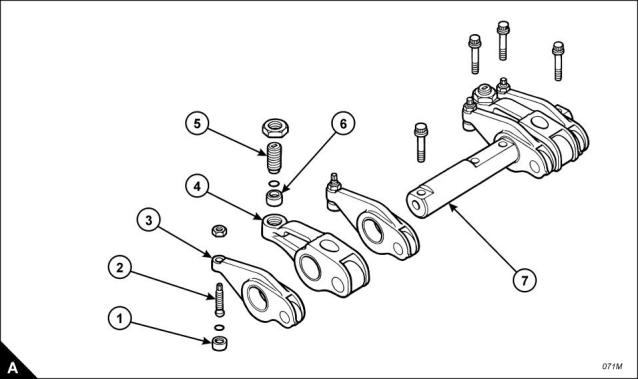
1 Slide the valve rocker levers (A3) and the unit injector rocker levers (A4) from the shaft (A7).
Note: Fit a new ‘O’ ring seal to any rocker lever adjuster if its button (A1) has been removed from the
adjustment screw (A2).
2 Remove the button (A1) from the adjustment screw (A2) in the valve rocker lever (A3).
3 Remove the button (A6) from the adjustment screw (A5) in the unit injector rocker lever (A4).
4 Repeat steps 1 to 3 for the rocker lever assemblies which remain.
30
Workshop Manual, TSD3455E, Issue 2
This document is printed from SPI². Not for RESALE
![]()
![]()
![]()
![]()
3
2300
To assemble
1 Install new ‘O’ ring seals in the buttons (A1).
2 Install new ‘O’ ring seals in the buttons (A6).
3 To fit the ‘O’ ring seals and buttons to the valve rocker levers, proceed as follows:
a. Support the valve rocker lever (A3) in a vice which has soft jaws.
b. Put the ‘O’ ring seal and button (A1) on the round end of the adjustment screw (A2).
c. Use a soft hammer to seat the button on the adjustment screw.
4 To fit the ‘O’ ring seals and buttons to the unit injector rocker levers, proceed as follows:
a. Support the unit injector rocker lever (A4) in a vice which has soft jaws.
b. Put the ‘O’ ring seal and button (A6) over the end of adjustment screw (A5).
c. Use a soft hammer to seat the button on the adjustment screw.
5 Repeat steps 3 and 4 for the rocker levers which remain.
6 Fit the assembled rocker levers to the shafts (A7). Ensure that they are fitted to their original positions.
Workshop Manual, TSD3455E, Issue 2
31
This document is printed from SPI². Not for RESALE
![]()
![]()

3
2300
How to check/adjust the tappet clearances
Operation 3-4
Special requirements
Special tools
Tappet clearances
Description
Part number
Inlet
Exhaust
Engine turning tool
CH11148
0,38 mm (0.015 in)
0,76 mm (0.030 in)
The tappet clearance is measured between the rocker levers and the top of the valve bridge pieces. The
operation must be done with the engine cold and stopped. Refer also to Operation 3-13, How to check/adjust
the electronic unit injectors.
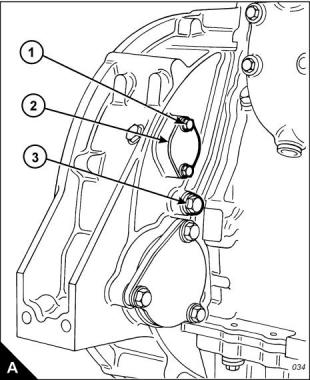
1 Remove the rocker cover, Operation 3-1.
2 Remove the cover (A2) from the flywheel housing. The top bolt (A1) is the timing bolt.
Caution: If a customer-fitted speed sensor is fitted to the flywheel housing, it must be removed before the
engine turning tool can be inserted.
3 Remove the plug (A3) from the timing bolt location in the flywheel housing and fit the timing bolt.
Note: There are two locations for the timing bolt, one at each side of the flywheel housing. Use the location
that is the most convenient.
4 Insert the engine turning tool, CH11148, into the flywheel housing through the aperture behind the cover
1
(A2). Use a / inch drive ratchet with the turning tool to rotate the engine flywheel in the normal direction of
2
rotation (anti-clockwise when viewed on the flywheel) until the timing bolt engages with the threaded hole in
the flywheel. The piston of number 1 cylinder is now at TDC (top dead centre).
Caution: If the flywheel is turned past the threaded hole, the flywheel must be turned in the opposite direction
for approximately 45 degrees and then back in the normal direction of rotation until the timing bolt engages
with the threaded hole. This is to eliminate backlash.
Continued
32
Workshop Manual, TSD3455E, Issue 2
This document is printed from SPI². Not for RESALE
![]()
![]()
![]()
![]()

3
2300
5 Check the inlet and exhaust valves of the number 1 cylinder. If they are fully closed the piston is on its
compression stroke and the rocker levers can be moved by hand. If the rocker levers can not be moved
because the valves are slightly open, the piston is on its exhaust stroke. If it is on its exhaust stroke, withdraw
the timing bolt and turn the flywheel a further 360 degrees in the normal direction of rotation so that the number
1 cylinder is set to TDC on its compression stroke, then insert again the timing bolt.
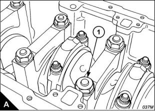
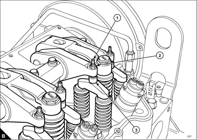
6 Before each set of tappet clearances is adjusted, ensure that the roller of the rocker lever is fully against the
camshaft lobe.
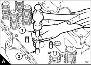
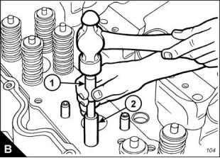
7 Use a set of feeler gauges, inserted at the position shown (B3) between the valve bridge piece and the rocker
lever button, to check the tappet clearances for the inlet valves (C1) on cylinders 1, 2 and 4. Adjust the
clearances if necessary. Check the tappet clearance for the exhaust valves (C2) on cylinders 1, 3 and 5, and
adjust the clearances if necessary.
Continued
Workshop Manual, TSD3455E, Issue 2
33
This document is printed from SPI². Not for RESALE
![]()
![]()
3
2300
Notes:
Move each valve bridge piece before the feeler gauge is inserted to reduce the effect of the oil film.
During the procedure, ensure that the feeler gauge is fully inserted
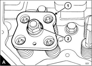
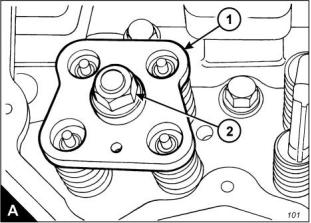
8 After each unit has been adjusted, tighten the lock nut (B2) of the adjustment screw (B1) to a torque of 30 +/
- 4 Nm (22 +/- 3 lbf ft).
9 Withdraw the timing bolt and rotate the flywheel by 360 degrees so that the number 6 piston is at TDC on
its compression stroke. Insert again the timing bolt into the threaded hole.
10 Check the tappet clearances for the inlet valves (C1) on cylinders 3, 5 and 6. Adjust the clearances if
necessary. Check the tappet clearances for the exhaust valves (C2) on cylinders 2, 4 and 6, and adjust the
clearances if necessary.
11 After each unit has been adjusted, tighten the lock nut of the adjustment screw to a torque of 30 +/- 4 Nm
(22 +/- 3 lbf ft).
12 Check again the tappet clearances for all six cylinders.
13 Fit the rocker cover. Remove the engine turning tool and the timing bolt and fit the cover to the flywheel
housing. Fit the plug to the timing bolt location.
34
Workshop Manual, TSD3455E, Issue 2
This document is printed from SPI². Not for RESALE
![]()
![]()
![]()
![]()
3
2300
Cylinder head assembly
To remove and to fit
Operation 3-5
Special requirements
Special tools
Description
Consumable products
Part number
GE50019
GE50020
VP12712
Description
Part number
Guide bolt, camshaft gear
Socket, cylinder head bolt
Lifting bracket
Special lubricant
CV60895
Retaining compound
21820 638
To remove
1 Remove the thermostat housing, Operation 12-10.
2 Remove the exhaust manifold, Operation 9-1.
3 Remove the rocker lever and rocker shaft assemblies, Operation 3-2.
4 Remove the electronic unit injectors, Operation 3-12.
5 Remove the gear case cover, Operation 6-1.
6 Disconnect the cable and remove the timing sensor from the cylinder head.
7 Remove the support bracket which is fitted between the gear case and the cylinder head.
8 Remove one bolt from the camshaft gear and install the guide stud, GE50019. Remove the five bolts which
remain and withdraw carefully the camshaft gear. Remove the guide stud.
9 Disconnect the fuel lines from the front and rear of the cylinder head. Fit temporary covers to the fuel lines
and also to the ports on the cylinder head.
10 Remove the cylinder head bolts; use the special socket, GE50020.
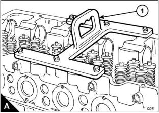
11 Fit the lifting bracket (A1), VP12712, to the cylinder head and attach a suitable hoist. Remove the cylinder
head. The cylinder head weighs approximately 148 kg (325 lb).
Continued
Workshop Manual, TSD3455E, Issue 2
35
This document is printed from SPI². Not for RESALE
![]()
![]()
![]()
![]()

3
2300
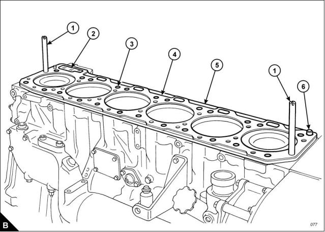
12 Remove the cylinder head gasket (B4).
13 Remove the ‘O’ ring seal from the oil transfer tube (B6) and remove the 24 coolant seals (B3).
14 Remove the seal (B2).
15 Remove the spacer plate (B5) and discard the spacer plate gasket.
16 Remove the second ‘O’ ring seal from the oil transfer tube (B6).
36
Workshop Manual, TSD3455E, Issue 2
This document is printed from SPI². Not for RESALE
![]()
![]()
3
2300
To fit
1 If the oil transfer tube (B6) has been removed, apply retaining compound, 21820 638, and insert it in the
crankcase. It must protrude from the top face of the crankcase by 20,0 +/- 0,5 mm (0.79 +/- 0.02 in). Remove
any excess compound and ensure that the bore of the oil transfer tube is clean.
2 If the rear dowel has been removed, apply retaining compound, 21820 638, and insert it in the crankcase.
It must protrude from the top face of the crankcase by 18,5 +/- 0,5 mm (0.73 +/- 0.02 in).
3 If the front dowel, close to the oil transfer tube, has been removed, it must be fitted in a dry condition. It must
protrude from the top face of the crankcase by 16,0 +/- 0,5 mm (0.63 +/- 0.02 in).
Note: Ensure that the spacer plate and the machined surface of the cylinder block are clean and free from dirt
and gasket material. Both surfaces of the spacer plate gasket and the top of the cylinder block must be clean.
Do NOT use a gasket adhesive on the surfaces.
4 Fit suitable guide studs (B1) to the cylinder block. Fit a new spacer plate gasket over the dowels in the
cylinder block.
Note: Apply a small amount of clean engine oil to the seals and ‘O’ ring seals before installation.
5 Fit a new ‘O’ ring seal to the oil transfer tube (B6).
6 Fit the spacer plate (B5) and fit the second ‘O’ ring seal to the oil transfer tube (B6). Fit the 24 coolant seals
(B3) and a new seal (B2) to the oil drain passage.
7 Check, and if necessary adjust, the protrusion of the cylinder liners, Operation 7-3.
8 Fit a new cylinder head gasket (B4) to the spacer plate.
Continued
Workshop Manual, TSD3455E, Issue 2
37
This document is printed from SPI². Not for RESALE
![]()
![]()

3
2300
9 Fasten a hoist to the cylinder head, use the lifting bracket VP12712, and lower the cylinder head onto the
spacer plate.
10 Apply special lubricant, CV60895, to the washers, the threads and under the heads of the bolts and fit the
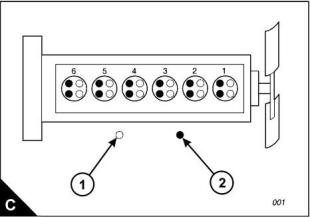
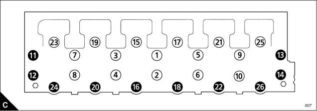
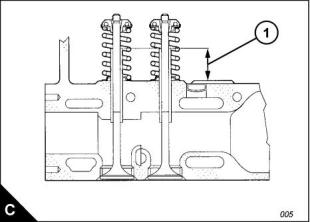
cylinder head bolts and washers. The long bolts must be fitted at the positions shown in the black circles (C).
Use the special socket, GE50020, and the procedure which follows to tighten the bolts correctly:
a. Tighten the cylinder head bolts in the sequence given (C) to a torque of 270 +/- 15 Nm (200 +/- 11 lbf ft).
b. Tighten the cylinder head bolts in the sequence given (C) to a torque of 450 +/- 20 Nm (333 +/- 15 lbf ft).
c. Again, tighten the cylinder head bolts in the sequence given (C) to a torque of 450 +/- 20 Nm (333 +/-
15 lbf ft).
Caution: After the cylinder head assembly has been removed and fitted, it is necessary to check the backlash
between the camshaft and the idler gears. Incorrect adjustment can cause damage to components.
11 Fit the camshaft gear. Check and, if necessary, adjust the backlash between the camshaft gear and the
idler gear, Operation 3-11.
12 Fit the gear case cover, Operation 6-1.
13 Fit the support bracket between the cylinder head and the gear case.
14 Fit the electronic unit injectors, Operation 3-12.
15 Fit the rocker lever and shaft assemblies, Operation 3-2.
16 Fit the exhaust manifold, Operation 9-1.
17 Fit the thermostat housing, Operation 12-10.
18 Remove the covers from the fuel lines and from the fuel line ports on the cylinder head. Connect the fuel
lines to the cylinder head and attach any relevant clamps.
19 Fit the timing sensor and connect the cable.
38
Workshop Manual, TSD3455E, Issue 2
This document is printed from SPI². Not for RESALE
![]()
![]()
3
2300
Valve springs
To remove and to fit
Operation 3-6
Special requirements
Special tools
Description
Part number
Valve spring compressor
GE50026
To remove
Note: The valve springs can be removed with the cylinder head either fitted to or removed from the engine.
The procedure given here is for use when the cylinder head is fitted to the engine. Before any components are
removed, ensure that the relevant piston is set to the top of its compression stroke. If the piston is not at this
position, the valves can fall into the cylinder liner.
Caution: If a valve falls into the cylinder liner, the cylinder head must be removed.
1 Remove the rocker lever and rocker shaft assemblies, Operation 3-2.
2 Remove the electronic unit injectors, Operation 3-12.
3 Set the piston for the relevant valve spring assembly to the top of its compression stroke.
4 Use the hold-down clamp from the electronic unit injector to secure the valve spring compressor, GE50026,
to the cylinder head.
5 Insert the stud and base of the valve spring compressor into the bore of the injector sleeve. Use the bolt and
clamp from the electronic unit injector to secure the stud and base to the cylinder head. Fit the compressor
plate (A1) over the stud and fit the thrust bearing, the washer and the nut (A2)
6 Tighten the nut until the collets are loose on the valves.
7 Remove two collets from each valve.
8 Loosen slowly, then remove the nut, washer, thrust bearing and plate.
9 Remove the rotocoils, valve springs and washers from each valve.
10 Inspect the valve springs, refer to Chapter 2, Specifications for the correct dimensions and spring force.
11 Repeat steps 3 to 10 for the other valve spring assemblies which are to be removed.
Workshop Manual, TSD3455E, Issue 2
39
This document is printed from SPI². Not for RESALE
![]()
![]()
![]()
![]()

3
2300
To fit
1 Apply clean engine oil to the relevant valve stems.
2 Fit the washer, valve spring and rotocoil to each valve.
3 Use the valve spring compressor, GE50026, to compress the valve springs.
Note: The collets are tapered. When fitted, the large (thick) diameter must be uppermost.
4 Fit two collets to each valve.
Caution: The collets can be dislodged from the valve stem during the removal of the valve spring compressor.
Ensure that the collets are seated correctly during this procedure.
5 Loosen slowly and then remove the nut (A2) and plate (A1) of the valve spring compressor. Remove the
other parts of the valve spring compressor tool and ensure that the collets are fitted correctly to the valve
stems.
6 Tap lightly each valve with a soft hammer to ensure that the collets are seated correctly.
7 Fit the electronic unit injectors, Operation 3-12.
8 Fit the rocker lever and rocker shaft assemblies, Operation 3-2.
40
Workshop Manual, TSD3455E, Issue 2
This document is printed from SPI². Not for RESALE
![]()
![]()
3
2300
Valves
To remove and to fit
Operation 3-7
Special requirements
Special tools
Description
Part number
Valve spring compressor
GE50026
To remove
1 Remove the cylinder head, Operation 3-5.
Note: If more than one valve is to be removed, make a note of the position of the valves as they are removed
from the cylinder head.
2 Put the cylinder head, flame face down, on a bench with a soft surface and release the valves by use of the
valve spring compressor, GE50026. Use the procedure given in Operation 3-6.
3 Withdraw the valves from the cylinder head.
4 Repeat the procedure for all valves which are to be removed.
To fit
1 Apply clean engine oil to the stems of the valves. Fit the valves to their original positions in the cylinder head.
2 Use the special tool, GE50026, and the procedure given in Operation 3-6, to install the valve springs.
3 Fit the cylinder head, Operation 3-5.
Workshop Manual, TSD3455E, Issue 2
41
This document is printed from SPI². Not for RESALE
![]()
![]()
![]()
![]()

3
2300
Valve seals
To renew
Operation 3-8
Special requirements
Special tools
Description
Part number
Insertion tool, valve seal
GE50027
Note: The valve seals can be removed with the cylinder head either fitted to or removed from the engine.
1 Remove the relevant valve spring assembly, Operation 3-6.
2 Remove the valve seal from the valve and valve guide.
3 Apply a thin film of clean engine oil to the new valve seal and slide the seal over the valve stem.
4 If the valve seal is to be fitted to a valve guide with the valve removed, fit the seal to the special tool,
GE50027. Insert the seal pin (part of the special tool GE50027) through the insertion tool, then enter the seal
pin into the bore of the valve guide.
5 Use the special tool, GE50027, and hand pressure only to push the valve seal into its position in the valve
guide.
6 Withdraw the tool and fit the valve spring assembly, Operation 3-6.
42
Workshop Manual, TSD3455E, Issue 2
This document is printed from SPI². Not for RESALE
![]()
![]()
![]()
![]()

3
2300
Valve guides
To remove and to fit
Operation 3-9
Special requirements
Special tools
Description
Removal/installation tool
Sleeve
Part number
GE50043
GE50044
To remove
1 Remove the cylinder head, Operation 3-5.
2 Remove the valves, Operation 3-7.
3 Use the special tool (A1), GE50043, and a hammer to drive the valve guide (A2) from the cylinder head.
Workshop Manual, TSD3455E, Issue 2
43
This document is printed from SPI². Not for RESALE
![]()
![]()
![]()
![]()

3
2300
To fit
1 Apply clean engine oil to the outside diameter of the new valve guides.
2 Use the special tool (B1), GE50043, together with the sleeve (B2), GE50044, to install the valve guide. The
guide must protrude from the cylinder head, as shown (C1), by 35,0 +/- 0,5 mm (1.38 +/- 0.02 in).
Refer to Chapter 2, Specifications for the correct dimensions for the inside diameter of new and used valve
guides.
3 When a new valve guide has been fitted, check that there is full contact between the valve and the valve
seat. If necessary, lap the valve to the seat.
4 Fit the valves, Operation 3-7.
5 Fit the cylinder head, Operation 3-5.
44
Workshop Manual, TSD3455E, Issue 2
This document is printed from SPI². Not for RESALE
![]()
![]()
3
2300
Camshaft
To remove and to fit
Operation 3-10
Special requirements
Special tools
Consumable products
Description
Part number
CH11148
GE50019
GE50018
GE50017
GE50015
GE50025
GE50016
Description
Part number
Engine turning tool
Thread lock compound (10 ml)
21820 117
Guide stud
Cradle tool
Camshaft guide
Pilot
Lifting hooks
Alignment sleeve
To remove
1 Remove the radiator, Operation 12-4.
2 Remove the fan, Operation 12-5.
3 Remove the gear case cover, Operation 6-1.
4 Remove the rocker cover, Operation 3-1.
5 Remove the rocker lever and shaft assemblies, Operation 3-2.
6 Remove the cover (A2) from the flywheel housing. The top bolt (A1) is the timing bolt.
7 Remove the plug (A3) from the timing bolt location in the flywheel housing and fit the timing bolt.
Note: There are two locations for the timing bolt, one at each side of the flywheel housing. Use the location
which is the most convenient.
Continued
Workshop Manual, TSD3455E, Issue 2
45
This document is printed from SPI². Not for RESALE
![]()
![]()
![]()
![]()


3
2300
8 Insert the engine turning tool, CH11148, into the flywheel housing through the aperture behind the cover
1
(A2). Use a / inch drive ratchet with the turning tool to rotate the engine flywheel in the normal direction of
2
rotation (anti-clockwise when viewed on the flywheel) until the timing bolt engages with the threaded hole in
the flywheel. The piston of number 1 cylinder is now at TDC (top dead centre). When the number one piston
is at top dead centre on its compression stroke, the mark on the camshaft gear is be aligned with the mark on
the gear case. If the mark is not aligned, withdraw the timing bolt, rotate the crankshaft a further 360 degrees
in the normal direction of rotation and insert the timing bolt again.
Cautions:
If the flywheel is turned past the threaded hole, the flywheel must be turned in the opposite direction for
approximately 45 degrees and then back in the normal direction of rotation until the timing bolt engages
with the threaded hole. This is to eliminate backlash.
Do not rotate the crankshaft with the camshaft gear or any of the idler gears removed and the rocker shaft
assemblies installed. Damage can be caused to the pistons and valves, or to both.
9 Disconnect the lead and remove camshaft timing sensor from behind the top of the gear case.
10 Remove one bolt from the camshaft gear and install the guide stud, GE50019. Remove the five bolts which
remain.
11 Attach a hoist to the camshaft gear and withdraw the gear from the camshaft. Remove the guide stud.
12 Remove three bolts and withdraw the thrust plate, the adaptor plate and the seal assembly.
Note: Take care during removal of the camshaft to ensure that the surfaces of both the camshaft and the
camshaft bearings are not damaged. Use the procedure which follows, together with the relevant special tools,
to avoid damage to the engine and components.
13 Use the bolts of the rocker shaft to retain the cradle tool (B1), GE50018, at the position shown (B).
Continued
46
Workshop Manual, TSD3455E, Issue 2
This document is printed from SPI². Not for RESALE
![]()
![]()
![]()
![]()
3
2300
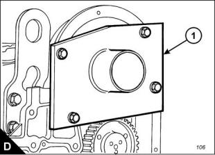
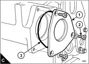
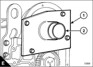
14 Remove the rear cover (C1), complete with seal (C3).
15 Fit the camshaft guide (D1), GE50017, to the gear case. Do not tighten the bolts for the guide at this stage.
Note: It is necessary to install two pilots, GE50015, on the rear end of the camshaft. The second pilot will
support the rear of the camshaft as it is moved from the cylinder head and into the guide, GE50017.
16 Install a pilot tool, GE50015, into the threaded hole at the rear end of the camshaft. Then attach the second
pilot tool, GE50015, to the first.
17 Withdraw the camshaft until it enters the bore of the camshaft guide. Tighten the bolts which retain the
guide on the gear case.
18 Use the lifting hooks, GE50025, to move the camshaft toward the front of the engine.
Caution: During use of the lifting hooks do not raise the camshaft; the camshaft should be supported by the
cradle, GE50018. If the camshaft is raised, damage to the camshaft bearings can occur.
19 Withdraw the camshaft from the cylinder head just enough for a strap and hoist to be attached. Attach a
suitable strap and hoist to support the camshaft, ensure that the camshaft is kept level and withdraw it from
the cylinder head. The camshaft weighs approximately 39 kg (85 lb).
Workshop Manual, TSD3455E, Issue 2
47
This document is printed from SPI². Not for RESALE
![]()
![]()
3
2300
To fit
1 Fit the two pilot tools, GE50015, to the rear end of the camshaft. Ensure that the camshaft and camshaft
bearings have been cleaned thoroughly. Apply clean engine oil to the lobes and journals of the camshaft. Apply
a thin coat of clean engine oil to the camshaft bearings.
2 Fit the camshaft guide (E1), GE50017, to the gear case cover, but do not tighten the bolts fully.
3 Insert the alignment sleeve (E2), GE50016, through the camshaft guide (E1) and into the camshaft bearings
to align the camshaft guide correctly. Tighten the bolts which retain the camshaft guide, GE50017, on the gear
case. Remove the alignment sleeve; the sleeve should move freely from the bore of the camshaft guide,
GE50017.
4 Fit the cradle tool (F1), GE50018, at the position shown (F).
Note: Rotate the camshaft in both directions during installation to prevent binding.
5 Use a suitable strap and hoist to support the camshaft. Insert the camshaft through the guide and into the
cylinder head. Move the camshaft into the head as far as the strap and hoist will allow.
6 Remove the strap and hoist. Rotate the camshaft during installation. Do not allow the end of the camshaft
to drop during removal of the hoist as the bearings can be damaged. Use the lifting hooks, GE50025, to
support the camshaft during installation.
7 Remove the pilot tools and push the camshaft fully into its bore.
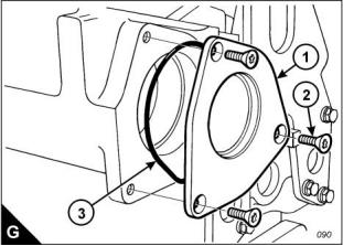
8 Inspect the seal (G3) and renew if necessary. Fit the rear cover (G1), complete with seal (G3).
Continued
48
Workshop Manual, TSD3455E, Issue 2
This document is printed from SPI². Not for RESALE
![]()
![]()
3
2300
9 Remove the cradle tool and the camshaft guide.
10 Fit new ‘O’ ring seals to the camshaft front seal plate. Apply a small amount of engine lubricating oil to the
‘O’ ring seal on the outside of the plate. Fit the seal plate with the face seal against the cylinder head. Insert
the adapter plate and fit the thrust plate. Apply thread lock compound, 21820 117, to the three bolts, fit the
bolts and tighten.
Note: Camshaft timing is very important. During installation of the camshaft assembly, ensure that the timing
marks on the camshaft gear and the gear case cover are aligned when number one cylinder is at top centre
(TDC).
11 Fit the guide stud, GE50019, to the camshaft.
12 Fit the camshaft gear; align the hole in the gear with the dowel pin on the adapter plate. If the timing mark
on gear does not align with the pointer at the top of the gear case, remove the gear and rotate the camshaft
until the gear can be installed with the marks aligned.
13 Fit the bolts which retain the gear, remove the guide stud and fit the bolt which remains. Tighten the bolts
to a torque of 240 +/- 40 Nm (177 +/- 30 lbf ft).
14 Fit the camshaft timing sensor to its location behind the top of the gear case and connect the lead.
15 Fit the gear case cover, Operation 6-1.
16 Remove the timing bolt from the flywheel and fit the cover and plug.
17 Install the rocker lever and shaft assemblies, Operation 3-2.
Workshop Manual, TSD3455E, Issue 2
49
This document is printed from SPI². Not for RESALE
![]()
![]()
3
2300
How to set the backlash for the camshaft gear
Operation 3-11
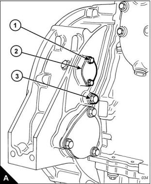
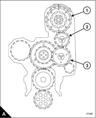
If the cylinder head or the camshaft is removed, the backlash between the camshaft gear (A1) and the
adjustable idler gear (A2) must be checked and, if necessary, adjusted. The backlash between the camshaft
gear and the adjustable idler gear, and also between the adjustable idler gear (A2) and the main idler gear
(A3), must be 0,25 +/- 0,08 mm (0.010 +/- 0.003 in).
Note: This procedure must be performed before the rocker lever and shaft assemblies are fitted.
1 Remove the main idler gear (A3). Hold the camshaft gear stationary and use a dial test indicator (DTI),
mounted on the gear case, to check the backlash of the adjustable idler gear.
2 Fit the main idler gear (A3), hold the main idler gear stationary and measure the backlash on the adjustable
idler gear.
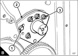
3 To adjust the backlash, remove the three bolts and thrust plate which retain the adjustable idler gear (A2)
and remove the gear. Loosen the five nuts (B3) and the bolt (B1) which retain the stub axle (B2) and move the
stub axle by the relevant amount. Tighten the nuts and bolt to a torque of 47 +/- 9 Nm (35 +/- 7 lbf ft).
4 Fit the idler gear. Retain with the thrust plate and three bolts. Check again the backlash between the
adjustable idler gear and the camshaft gear, and also between the adjustable idler gear (A2) , and the main idler
gear (A3), as given in steps 1 and 2. Repeat the procedure if necessary until the correct backlash settings have
been obtained.
5 When the correct backlash settings have been obtained, remove the adjustable idler gear and proceed as
follows: Remove one of the nuts which retains the idler axle, apply a small amount of Loctite 542 to the threads
of the stud, fit the nut and tighten to a torque of 47 +/- 9 Nm (35 +/- 7 lbf ft). Repeat this procedure for the other
four nuts and the bolt; work on one nut or bolt at a time so that the position of the stub axle is not affected.
50
Workshop Manual, TSD3455E, Issue 2
This document is printed from SPI². Not for RESALE
![]()
![]()
![]()
![]()
3
2300
Electronic injector units
To remove and to fit
Operation 3-12
Special requirements
Special tools
Description
Injector installer/removal
Vacuum pump
Tube
Part number
Description
Part number
GE50022
GE50021
GE50028
GE50030
GE50029
Brush
Brush
GE50023
Brush
GE50024
Bottle
To remove
Warning! The electrical circuit for the fuel injector units operates on 110 volts. Do NOT work on the fuel injector
units unless the power supply to the ECM has been disconnected.
1 Remove the relevant rocker shaft assembly, Operation 3-2.
2 Loosen the two nuts and remove the electrical connector from the injector unit.
3 Mark the valve bridge pieces to assist during assembly, then remove them.
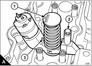
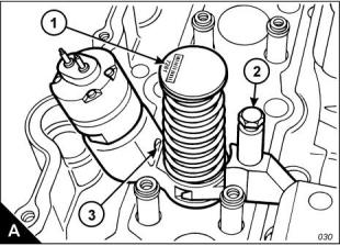
4 Remove the bolt (A2) from the spacer and clamp which retain the injector unit and use the special tool,
GE50021, to release the injector unit from the cylinder head.
Caution: If more than one injector unit is to be removed, make a note of the trim code (A1), a four-digit number
adjacent to the bar code, and also the cylinder to which the unit is fitted.
5 Remove the injector unit, together with the spacer and clamp.
6 Use the vacuum pump, GE50028, together with the tube, GE50030, and bottle, GE50029, to extract any
fuel which has spilled into the combustion chamber during removal of the injector.
Workshop Manual, TSD3455E, Issue 2
51
This document is printed from SPI². Not for RESALE
![]()
![]()
![]()
![]()

3
2300
To fit
1 Clean thoroughly the bore of the injector sleeve and cylinder head. Use the special brushes (GE50022,
GE50023 and GE50024) to remove carbon or dirt.
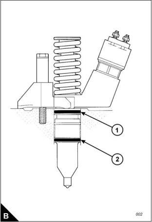
2 Check the condition of the ‘O’ ring seals (B1 and B2); renew the seals if they are worn or damaged. Lubricate
the ‘O’ ring seals with clean engine oil before the injector unit is installed in the cylinder head.
Caution: Injector units MUST be fitted to their original positions or the information in the ECM will need to be
updated.
3 Fit the injector unit to the cylinder head. Fit the clamp, spacer and retaining bolt. Tighten the bolt (A2) to a
torque of 47 +/- 9 Nm (35 +/- 7 lbf ft).
4 Fit the bridge pieces.
5 Attach the electrical connector to the injector unit and retain with the two nuts. Tighten the nuts to a torque
of 2,5 Nm (22 lbf in).
6 Fit the rocker shaft assembly, Operation 3-2.
52
Workshop Manual, TSD3455E, Issue 2
This document is printed from SPI². Not for RESALE
![]()
![]()
3
2300
To check and to adjust
Operation 3-13
Special requirements
Special tools
Description
Part number
Injector height gauge
CH11149
This operation should be performed at the same time as the operation to check the valve tappet clearances.
Warning! The electrical circuit for the fuel injector units operates on 110 volts. Do NOT work on the fuel injector
units unless the power supply to the ECM has been disconnected.
1 With the rocker covers removed, set the number 1 piston to TDC (top dead centre) on its compression
stroke. Check/adjust the height dimensions for the fuel injectors of cylinders 3, 5 and 6.
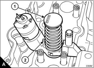
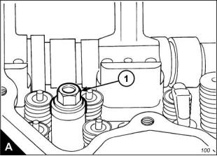
2 Use the fuel injector setting gauge, CH11149, to obtain the correct height for the fuel injector. The dimension
to be measured is from the top of the unit injector (A1) to the machined ledge on the fuel injector body (A2).
This dimension should be 78,0 +/- 0,2 mm (3.07 +/- 0.01 in). Slacken the lock nut and use the adjustment screw
of the rocker lever to obtain the correct dimension. Tighten the lock nut to a torque of 55 +/- 10 Nm (41 +/-
7 lbf ft).
3 Remove the timing bolt from the flywheel housing and rotate the flywheel by 360 degrees in the normal
direction of engine rotation until the timing bolt can be inserted into the threaded hole. This will put the number
1 piston at TDC in its exhaust stroke.
4 Check/adjust the height dimensions for the fuel injectors of cylinders 1, 2 and 4 as given in step 2.
When all adjustments have been made, remove the timing bolt, fit the cover to the flywheel housing, fit the plug
to the timing bolt position and fit the rocker covers.
Workshop Manual, TSD3455E, Issue 2
53
This document is printed from SPI². Not for RESALE
![]()
![]()
![]()
![]()

3
2300
Injector sleeves
To remove and to fit
Operation 3-14
Special requirements
Special tools
Description
Injector installer/removal
Vacuum pump
Tube
Part number
Description
Part number
GE50022
GE50021
GE50028
GE50030
GE50029
Brush
Brush
GE50023
Brush
GE50024
Bottle
To remove
1 Remove the rocker shaft assemblies, Operation 3-2.
2 Remove the electronic injector units, Operation 3-12.
3 Mark the bridge pieces and make a note of their position to assist during assembly, then remove the bridge
pieces.
4 Fit the puller stud from the special tool, GE50021, into the injector sleeve as shown (A). Fit the bridge, thrust
bearing, washer and nut, from the special tool, over the stud as shown. Tighten the nut (A1) of the special tool
until the sleeve is drawn from the cylinder head. Remove the special tool from the sleeve.
5 Remove the ‘O’ ring seals from the injector sleeve. Check the condition of the injector sleeve and renew if
necessary.
6 Repeat steps 1 to 5 for the injector sleeves which remain.
54
Workshop Manual, TSD3455E, Issue 2
This document is printed from SPI². Not for RESALE
![]()
![]()
![]()
![]()

3
2300
To fit
Caution: Before installation ensure that the injector sleeve and its bore in the cylinder head are clean and free
from oil, dirt and sealant.
1 Use the brushes, special tool numbers: GE50023, GE50024 and GE50022, to clean thoroughly the bore for
the injector sleeve.
Caution: Ensure that the fuel passage in the cylinder head is clean.
2 Fit new ‘O’ ring seals to the injector sleeve.
3 Fit the stud from the special tool into the threads of the injector sleeve.
Caution: Do not apply retaining and anti-seize compounds to the cylinder head surfaces. These compounds
must ONLY be applied to the injector sleeve.
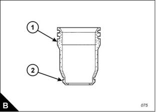
4 Apply CV60889 anti-seize compound to the ‘O’ ring seals and to the large diameter (B1) off the injector
sleeve.
5 Apply CV60893 retaining compound to the small diameter (B2) off the injector sleeve.
6 Using the stud, insert the injector sleeve into its bore in the cylinder head. Take care to prevent damage to
the ‘O’ ring seals. Use that only hand force is used to push the injector sleeve into the cylinder head.
7 Fit the driver tool over the stud and tap lightly with a hammer to ensure that the injector sleeve is fully seated
in the cylinder head. The tool and sleeve will "ring" when the sleeve is in full contact with the base of the bore.
8 Use a clean cloth to remove any retaining or anti-seize compound from the bores of the cylinder and injector
sleeve.
9 Fit the electronic injector units, Operation 3-12.
10 Fit the rocker shaft assemblies, Operation 3-2.
Workshop Manual, TSD3455E, Issue 2
55
This document is printed from SPI². Not for RESALE
![]()
![]()
This page is intentionally blank
This document is printed from SPI². Not for RESALE
2300
4
Pistons and connecting rod assemblies
4
General information
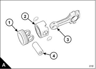
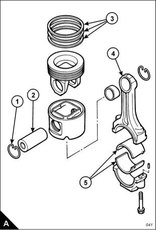
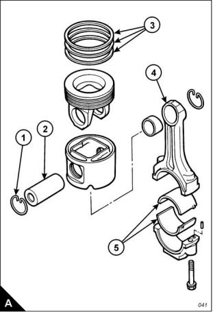
The pistons fitted to the 2300 and 2800 Series engines consist of two parts: a forged steel crown (A1) and a
cast aluminium skirt (A2). The two parts are retained on the connecting rod by the gudgeon pin (A4). The
pistons each have three rings fitted to grooves in the crown. The top ring is keystone shaped and its face is
plasma coated. The second ring has a tapered face which has a chrome finish. The third ring is an oil control
ring and also has a chrome finish on its face. The oil control ring contains a coil spring which expands the ring.
Small holes in the piston groove allow oil from the oil control ring to drain back to the sump.
The connecting rods are of a conventional design. The small end is wedge shaped and the big end bearing
cap is retained by two special bolts. A split type shell bearing is fitted at the big end and a single piece bearing
is pressed into the small end.
Piston squirter jets provide a supply of oil to cool the piston crown. On 2806 engines, an oil cooling chamber
is formed by the lip at the top of the piston skirt and the cavity behind the ring grooves in the piston crown. The
oil returns to the sump through the clearance gap between the crown and the skirt. For pistons fitted to the
2306 engine, the oil cooling chamber is formed between the cavity behind the ring grooves and two flat plates
fitted in the piston crown. There is a hole in each plate; the oil supply is squirted through one hole, flows around
the cooling chamber and returns to the sump through the hole at the opposite side.
Workshop Manual, TSD3455E, Issue 2
57
This document is printed from SPI². Not for RESALE
![]()
![]()
4
2300
Pistons and connecting rod assemblies
To remove and to fit
Operation 4-1
Special requirements
Special tools
Consumable products
Description
Installer, piston (2806 engine)
Installer, piston (2306 engine)
Part number
GE50003
Description
Part number
Anti-seize compound
CV60890
GE50045
To remove
1 Remove the cylinder head assembly, Operation 3-5.
2 Remove the oil pump, Operation 10-4.
3 Remove the stiffener plate from the base of the crankcase.
4 Remove the carbon ridge from the top inside surface of the cylinder liners.
5 Turn the crankshaft until two pistons are at bottom centre.
6 Remove the bolts (A1) and the bearing caps. Push the connecting rods and pistons up until the rings are
free from the cylinder liners.
7 Withdraw carefully the pistons and connecting rods from the cylinder liners. Store the bearing caps with their
relevant connecting rods.
8 Repeat steps 3 to 6 for the remainder of the pistons and connecting rods.
58
Workshop Manual, TSD3455E, Issue 2
This document is printed from SPI². Not for RESALE
![]()
![]()
![]()
![]()

4
2300
To fit
1 Apply clean engine oil to the piston rings, the connecting rod bearings and the cylinder liners.
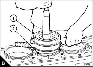
2 Ensure that the piston ring gaps are set at 120 degree intervals to each other.
3 Use the special tool (B1), GE50003 for 2806 engines or GE50045 for 2306 engines, to install the piston and
the connecting rod in the cylinder liner (B2). The connecting rod must be fitted with tab groove side of the big
end bearing at the opposite side to the camshaft. Proceed with care to ensure that the piston rings are not
damaged during the operation.
Caution: Bearing caps must be fitted to their original connecting rods,
4 Fit the bearing cap to the connecting rod. The cap must be fitted with its number on the same side as that
on the connecting rod and the number must be the same.
5 Apply anti-seize compound, CV60890, to the bolt threads. Install the bolts and bearing cap. Tighten each
bolt in the bearing cap to a torque of 90 +/- 8 Nm (66 +/- 6 lbf ft). Make a temporary mark on each bolt and the
bearing cap, then tighten each bolt by an additional 90 +/- 5 degrees.
6 Repeat steps 1 to 4 for the remainder of the pistons and connecting rods.
7 Fit the stiffener plate to the base of the crankcase.
8 Fit the oil pump, Operation 10-4.
9 Fit the cylinder head assembly, Operation 3-5.
Workshop Manual, TSD3455E, Issue 2
59
This document is printed from SPI². Not for RESALE
![]()
![]()
4
2300
To dismantle and assemble
Operation 4-2
To dismantle
1 Remove the pistons and connecting rod assemblies, Operation 4-1.
2 Remove the big-end bearing shells (A5) from the connecting rod (A4) and connecting rod cap. If the bearings
are to be used again, make a note of the position where they were fitted.
3 Remove the circlips (A1).
4 Remove the gudgeon pin (A2) and separate the connecting rod and the piston crown from the piston.
5 Remove carefully the piston rings (A3) from the piston crown and clean the piston ring grooves with a
suitable cleaning tool.
Special equipment is required to renew the small end bearing. If this operation becomes necessary, contact
your Perkins dealer.
60
Workshop Manual, TSD3455E, Issue 2
This document is printed from SPI². Not for RESALE
![]()
![]()
![]()
![]()
4
2300
To assemble
1 Check the gaps between the ends of the piston rings when the rings are inserted in a new liner. The rings
can also be checked by insertion in an unworn part of a used liner.
For the correct dimensions refer to Chapter 2, Specifications.
2 Fit the spring of the oil control ring to its groove in the piston crown.
Note: The oil control ring must be fitted over the spring with the gap of the oil control ring at 180 degrees from
the joint of the spring.
3 Use a suitable piston ring expander to fit the oil control ring to its groove in the piston crown.
4 Fit the second (intermediate) piston ring with the side that has the identification "UP-2" toward the top of the
piston. Use a suitable piston ring expander.
5 Fit the first (top) piston ring with the side that has the identification "UP-1" toward the top of the piston. Use
a suitable piston ring expander.
6 When all three piston rings have been fitted, adjust the position of the piston ring gaps so that they are
120 degrees apart.
7 Fit the piston crown into the piston skirt and insert the connecting rod. Apply clean engine oil to the gudgeon
pin (A2) and install the pin. Fit the circlips (A1). Ensure that the circlips are located fully in the grooves of the
piston.
8 Fit the big-end bearings to the connecting rod (A4) and connecting rod cap. If the original bearings are to be
used, ensure that they are fitted to their original positions.
Note: The tabs at back of the bearings must be located correctly in the tab slots of the connecting rod and
connecting rod cap.
9 Fit the pistons and connecting rod assemblies, Operation 4-1.
Workshop Manual, TSD3455E, Issue 2
61
This document is printed from SPI². Not for RESALE
![]()
![]()
4
2300
Piston cooling jets
To remove and to fit
Operation 4-3
Special requirements
Special tools
Description
Part number
CH11148
Engine turning tool
Jet alignment tool
GE50004
To remove
1 Remove oil pump, Operation 10-4.
2 Use the engine turning tool, CH11148, to turn the crankshaft in a clockwise direction (as seen from the front
of the engine) to obtain access to the relevant piston cooling jet.
3 Remove the bolt which retains the cooling jet and remove the cooling jet from the engine.
4 Repeat steps 2 and 3 for the cooling jets which remain.
To fit
1 Before a piston cooling jet is fitted to the engine, use the jet alignment tool, GE50004, to ensure that the
direction of the nozzles is correct.
Caution: If, when fitted to the alignment tool, a nozzle does not align correctly with the relevant dowel, discard
the cooling jet; do NOT fit a damaged or distorted cooling jet to the engine.
2 Carefully fit the piston cooling jets to the engine, ensure that the nozzles of the cooling jets are not damaged
or distorted during the operation. Turn the crankshaft clockwise (as seen from the front of the engine) as
necessary to obtain access to the relevant positions.
3 Fit the oil pump, Operation 10-4.
62
Workshop Manual, TSD3455E, Issue 2
This document is printed from SPI². Not for RESALE
![]()
![]()
![]()
![]()

2300
5
Crankshaft assembly
5
General information
The crankshaft fitted to the 2300 and 2800 Series engines has 13 bearing surfaces, which consists of seven
main journals and six crank pins. Each crank pin holds two connecting rods.
Eight counterweights are included within the crankshaft forging and a vibration damper is fitted at the front end
to reduce torsional vibrations.
A gear at the front end of the crankshaft provides the drive for the engine timing gears, the coolant pump and
the lubricating oil pump.
To seal the crankcase, crankshaft seals are fitted in the gear case and the flywheel housing.
Workshop Manual, TSD3455E, Issue 2
63
This document is printed from SPI². Not for RESALE
![]()
![]()
5
2300
Crankshaft
To remove and to fit
Operation 5-1
Special requirements
Consumable products
Description
Part number
Anti-seize compound
CV60890
To remove
1 Remove the gear case cover, Operation 6-1.
2 Remove the flywheel housing, Operation 13-2.
3 Remove the pistons and connecting rod assemblies, Operation 4-1.
4 Remove the crankshaft rear seal and wear sleeve, Operation 5-3.
5 Remove the crankshaft front seal and wear sleeve, Operation 5-2.
Note: Make a note of the number on the bearing caps for assembly purposes. If a number cannot be seen, put
a number on the left side of the crankcase with a corresponding number on the bearing cap.
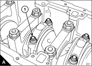
6 Remove the bolts (A1) which retain the main bearing caps in the crankcase and remove the bearing caps.
7 Fit one of the bolts from the front pulley to each end of the crankshaft. Fasten a hoist to the crankshaft and
lift the crankshaft from the crankcase. The weight of the crankshaft is approximately 159 kg (350 lb).
Note: If new main bearings are not to be installed, make a note of the position of the used bearings. Used
bearings must be fitted to their original positions.
64
Workshop Manual, TSD3455E, Issue 2
This document is printed from SPI². Not for RESALE
![]()
![]()
![]()
![]()