 English
 Espaol
 Franais
 阿拉伯
阿拉伯 中文
中文 Deutsch
 Italiano
 Português
 日本
日本 韩国
韩国 български
 hrvatski
 esky
esky Dansk
Dansk Nederlands
 suomi
suomi Ελληνικ
 印度
印度 norsk
norsk Polski
 Roman
Roman русский
 Svenska
珀金斯Perkins2206-E13操作保养维修供应商,珀金斯Perkins2206-E13操作保养维修技术价格规格咨询服务,珀金斯Perkins2206-E13操作保养维修零配件供应,珀金斯Perkins2206-E13操作保养维修售后服务中心,珀金斯Perkins2206-E13操作保养维修,珀金斯Perkins2206-E13操作保养维修详细的技术参数,

产品中心
珀金斯Perkins2206-E13操作保养维修
详细描述
Operation and
Maintenance
Manual
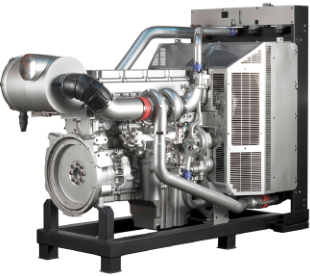
2206-E13 Industrial Engine
TGB (Engine)
TGD (Engine)
TGF (Engine)
Electronic Control Module 9
The ECM controls the engine operating parameters
through the software within the ECM and the inputs
from the various sensors. The software within the
ECM can be changed by installing a new flash file.
The flash file defines the following characteristics
of the engine:Engine power, Torque curves, Engine
speed (rpm), Engine Noise, Smoke, and Emissions.
This document has been printed from SPI². Not for Resale
![]()
SEBU8337
29
Operation Section
Engine Diagnostics
Engine Diagnostics
i02651197
Engine Operation with Active
Diagnostic Codes
i02784187
Self-Diagnostics
If a diagnostic lamp illuminates during normal engine
operation, the system has identified a situation that is
not within the specification. Use the electronic service
tool to check the active diagnostic codes.
The electronic control module has some
self-diagnostic ability. When an electronic problem
with an input or an output is detected, a diagnostic
code is generated. This indicates the specific problem
with the circuitry.
The active diagnostic code should be investigated.
The cause of the problem should be corrected as
soon as possible. If the cause of the active diagnostic
code is repaired and there is only one active
diagnostic code, the diagnostic lamp will turn off.
A diagnostic code which represents a problem that
currently exists is called an active code.
A diagnostic code that is stored in memory is called
a logged code. Always service active codes prior to
servicing logged codes. Logged codes may indicate
intermittent problems.
Operation of the engine and performance of the
engine can be limited as a result of the active
diagnostic code that is generated. Acceleration rates
may be significantly slower and power outputs may
be automatically reduced. Refer to Troubleshooting
, “Troubleshooting with a Diagnostic Code” for more
information on the relationship between each active
diagnostic code and the possible effect on engine
performance.
Logged codes may not indicate that a repair is
needed. The problems may have been repaired since
the logging of the code. Logged codes may be helpful
to troubleshoot intermittent problems.
i02572812
i02784585
Engine Operation with
Diagnostic Lamp
Intermittent Diagnostic Codes
The “DIAGNOSTIC” lamp is used to indicate the
existence of an active fault.
If a diagnostic lamp illuminates during normal engine
operation and the diagnostic lamp shuts OFF, an
intermittent fault may have occurred. If a fault has
occurred, the fault will be logged into the memory of
the Electronic Control Module (ECM).
A fault diagnostic code will remain active until the
problem is repaired.
i02784192
Fault Logging
In most cases, it is not necessary to stop the engine
because of an intermittent code. However, the
operator should retrieve the logged fault codes
and the operator should reference the appropriate
information in order to identify the nature of the fault.
The operator should log any observation that could
have caused the lamp to light.
The system provides the capability of Fault Logging.
When the Electronic Control Module (ECM)
generates an active diagnostic code, the code will
be logged in the memory of the ECM. The Perkins
electronic service tool can retrieve codes that have
been logged. The codes that have been logged can
be cleared with the Perkins electronic service tool.
The codes that have been logged in the memory
of the ECM will be automatically cleared from the
memory after 100 hours.
• Low power
• Limits of the engine speed
• Excessive smoke, etc
This information can be useful to help troubleshoot
the situation. The information can also be used for
future reference. For more information on diagnostic
codes, refer to the Troubleshooting guide for this
engine.
This document has been printed from SPI². Not for Resale
![]()
30
SEBU8337
Operation Section
Engine Starting
Engine Starting
i02583442
Starting the Engine
i02773196
Before Starting Engine
Note: Do not adjust the engine speed control during
start-up. The electronic control module (ECM) will
control the engine speed during start-up.
Before the engine is started, perform the required
daily maintenance and any other periodic
maintenance that is due. Refer to the Operation
and Maintenance Manual, “Maintenance Interval
Schedule” for more information.
New engines
Prime the turbocharger. This can be achieved by
cranking the engine briefly with no fuel.
• Open the fuel supply valve (if equipped).
If necessary, stop a new engine if an overspeed
condition occurs. If necessary, press the Emergency
Stop button.
NOTICE
All valves in the fuel return line must be open before
and during engine operation to help prevent high fuel
pressure. High fuel pressure may cause filter housing
failure or other damage.
Starting the Engine
1. Move the ignition switch to the ON position. If a
system fault is indicated, investigate the cause. If
necessary, use the Perkins electronic service tool.
If the engine has not been started for several weeks,
fuel may have drained from the fuel system. Air
may have entered the filter housing. Also, when fuel
filters have been changed, some air pockets will be
trapped in the engine. In these instances, prime the
fuel system. Refer to the Operation and Maintenance
Manual, “Fuel System - Prime” for more information
on priming the fuel system.
2. Push the start button or turn the keyswitch to the
START position in order to crank the engine.
3. If the engine fails to start within 30 seconds,
release the start button or the ignition switch. Wait
for 30 seconds in order to allow the starting motor
to cool before attempting to start the engine again.
Note: A system fault may be indicated after the
engine is started. If this occurs the ECM has detected
a problem with the system. If necessary, use the
Perkins Service Tool to investigate the problem.
Engine exhaust contains products of combustion
which may be harmful to your health. Always start
and operate the engine in a well ventilated area
and, if in an enclosed area, vent the exhaust to the
outside.
Note: Oil pressure should rise within 15 seconds
after the engine starts. The engine electronic controls
monitor the engine oil pressure. The electronic
controls will stop the engine if the oil pressure is
below normal.
• Do not start the engine or move any of the controls
if there is a “DO NOT OPERATE” warning tag or
similar warning tag attached to the start switch or
to the controls.
4. When possible, allow the engine to run at no load
for approximately three minutes. Run the engine
at no load until the water temperature gauge
has started to rise. Check all gauges during the
warm-up period.
• Reset all of the shutoffs or alarm components (if
equipped).
• Ensure that any equipment that is driven by the
engine has been disengaged from the engine.
Minimize electrical loads or remove any electrical
loads.
• Ensure that the coolant level is correct.
• Ensure that the engine oil level is correct.
This document has been printed from SPI². Not for Resale
![]()
![]()
![]()
![]()
![]()
SEBU8337
31
Operation Section
Engine Starting
i02815193
4. Operate the engine at no load until all the coolant
temperature starts to rise. Check the gauges
during the warm-up period.
Cold Weather Starting
Note: The oil pressures and fuel pressures should
be in the normal range on the instrument panel. Do
not apply a load to the engine until the oil pressure
gauge indicates at least normal pressure. Inspect the
engine for leaks and/or unusual noises.
Do not use aerosol types of starting aids such as
ether. Such use could result in an explosion and
personal injury.
Note: After the ECM has completed the cold mode,
cold mode cannot be enabled again until the ECM is
switched OFF.
The engine will start at a temperature of −10 °C
(14 °F). The ability to start at temperatures below
10 °C (50 °F) will improve by the use of a cylinder
block coolant heater or a device which heats the
crankcase oil. This will help to reduce white smoke
and misfires when the engine is started in cold
weather.
Note: Do not attempt to restart the engine until the
engine has completely stopped.
i02428473
Starting with Jump Start
Cables
If the engine has not been run for several weeks, fuel
may have drained. Air may have moved into the filter
housing. Also, when fuel filters have been changed,
some air will be left in the filter housing. Refer to
Operation and Maintenance Manual, “Fuel System -
Prime” in order to remove air from the fuel system.
Do not use jump start cables in order to start the
engine. Charge the batteries or replace the batteries.
Refer to Operation and Maintenance Manual,
“Battery - Replace”.
Use the procedure that follows for cold weather
starting.
NOTICE
Do not engage the starting motor when flywheel is
turning. Do not start the engine under load.
If the engine fails to start within 30 seconds, release
the starter switch or button and wait thirty seconds to
allow the starting motor to cool before attempting to
start the engine again.
1. If equipped, press the start button. If equipped,
turn the keyswitch to the START position in order
to engage the electric starting motor and crank
the engine.
2. Repeat step 1 three times if the engine fails to
start.
3. If the engine fails to start, investigate the problem.
Use the Perkins electronic service tool. A system
fault may be indicated after the engine is started. If
this occurs the ECM has detected a problem with
the system. Investigate the cause of the problem.
Use the Perkins electronic service tool.
Note: Oil pressure should rise within 15 seconds
after the engine starts. The electronic engine controls
monitor the oil pressure. The electronic controls will
stop the engine if the oil pressure is below normal.
This document has been printed from SPI². Not for Resale
![]()
![]()
![]()
![]()
![]()
32
SEBU8337
Operation Section
Engine Starting
i01646248
After Starting Engine
Note: In temperatures from 0 to 60°C (32 to 140°F),
the warm-up time is approximately three minutes. In
temperatures below 0°C (32°F), additional warm-up
time may be required.
Note: Ensure that the self test for the monitoring
system (if equipped) is completed before operating
the engine under load.
When the engine idles during warm-up, observe the
following conditions:
• Check for any fluid or for any air leaks at idle rpm
and at one-half full rpm (no load on the engine)
before operating the engine under load. This is not
possible in some applications.
• Operate the engine at low idle until all systems
achieve operating temperatures. Check all gauges
during the warm-up period.
Note: Gauge readings should be observed and
the data should be recorded frequently while the
engine is operating. Comparing the data over time
will help to determine normal readings for each
gauge. Comparing data over time will also help
detect abnormal operating developments. Significant
changes in the readings should be investigated.
This document has been printed from SPI². Not for Resale
![]()
SEBU8337
33
Operation Section
Engine Operation
Engine Operation
i02583385
Fuel Conservation Practices
i02578030
Engine Operation
The efficiency of the engine can affect the fuel
economy. Perkins design and technology in
manufacturing provides maximum fuel efficiency in
all applications. Follow the recommended procedures
in order to attain optimum performance for the life
of the engine.
Correct operation and maintenance are key factors
in obtaining the maximum life and economy of
the engine. If the directions in the Operation and
Maintenance Manual are followed, costs can be
minimized and engine service life can be maximized.
• Avoid spilling fuel.
Gauge readings should be observed and the data
should be recorded frequently while the engine
is operating. Comparing the data over time will
help to determine normal readings for each gauge.
Comparing data over time will also help detect
abnormal operating developments. Significant
changes in the readings should be investigated.
Fuel expands when the fuel is warmed up. The fuel
may overflow from the fuel tank. Inspect fuel lines for
leaks. Repair the fuel lines, as needed.
• Be aware of the properties of the different fuels.
Use only the recommended fuels.
• Avoid unnecessary operation at no load.
Shut off the engine instead of operating the engine
at no load for long periods of time.
• Observe the service indicator for the air cleaner
frequently, if equipped. Keep the air cleaner
elements clean.
• Maintain a good electrical system.
One bad battery cell will overwork the alternator. This
will consume excess power and excess fuel.
• Ensure that the belts are properly adjusted. The
belts should be in good condition.
• Ensure that all of the connections of the hoses are
tight. The connections should not leak.
• Ensure that the driven equipment is in good
working order.
• Cold engines consume excess fuel. Keep cooling
system components clean and keep cooling
system components in good repair. Never operate
the engine without water temperature regulators.
All of these items will help maintain operating
temperatures.
This document has been printed from SPI². Not for Resale
![]()
34
SEBU8337
Operation Section
Engine Stopping
Engine Stopping
i02583411
After Stopping Engine
i02572824
Manual Stop Procedure
Note: Before you check the engine oil, do not operate
the engine for at least 10 minutes in order to allow
the engine oil to return to the oil pan.
Stopping the Engine
• Check the crankcase oil level. Maintain the oil level
between the “LOW” mark and the “HIGH” mark on
the oil level gauge.
NOTICE
Stopping the engine immediately after it has been
working under load, can result in overheating and ac-
celerated wear of the engine components.
Note: Only use oil that is recommended in
this Operation and Maintenance Manual, “Fluid
Recommendations”. Failure to use the recommended
oil may result in engine damage.
Avoid accelerating the engine prior to shutting it down.
Avoiding hot engine shutdowns will maximize tur-
bocharger shaft and bearing life.
• If necessary, perform minor adjustments. Repair
any leaks and tighten any loose bolts.
• Note the service hour meter reading. Perform
the maintenance that is in the Operation and
Maintenance Manual, “Maintenance Interval
Schedule”.
Note: Individual applications will have different
control systems. Ensure that the shutoff procedures
are understood. Use the following general guidelines
in order to stop the engine.
• Fill the fuel tank in order to help prevent
accumulation of moisture in the fuel. Do not overfill
the fuel tank.
1. Remove the load from the engine. Allow the
engine to run under no load conditions for five
minutes in order to cool the engine.
• Allow the engine to cool. Check the coolant level.
Maintain the cooling system at 13 mm (0.5 inch)
from the bottom of the pipe for filling.
2. Stop the engine after the cool down period
according to the shutoff system on the engine and
turn the ignition keyswitch to the OFF position.
If necessary, refer to the instructions that are
provided by the OEM.
Note: Only use coolant that is recommended in
this Operation and Maintenance Manual, “Fluid
Recommendations”. Failure to use the recommended
oil may result in engine damage.
Emergency Stopping
• If freezing temperatures are expected, check
the coolant for proper antifreeze protection. The
cooling system must be protected against freezing
to the lowest expected outside temperature. Add
the proper coolant/water mixture, if necessary.
NOTICE
Emergency shutoff controls are for EMERGENCY use
ONLY. DO NOT use emergency shutoff devices or
controls for normal stopping procedure.
• Perform all required periodic maintenance on all
driven equipment. This maintenance is outlined in
the instructions from the OEM.
The OEM may have equipped the application with
an emergency stop button. For more information
about the emergency stop button, refer to the OEM
information.
Ensure that any components for the external system
that support the engine operation are secured after
the engine is stopped.
This document has been printed from SPI². Not for Resale
![]()
![]()
![]()
![]()
![]()
SEBU8337
35
Operation Section
Cold Weather Operation
Cold Weather Operation
Personal injury or property damage can result
from alcohol or starting fluids.
i02581613
Cold Weather Operation
Alcohol or starting fluids are highly flammable and
toxic and if improperly stored could result in injury
or property damage.
Perkins Diesel Engines can operate effectively in
cold weather. During cold weather, the starting and
the operation of the diesel engine is dependent on
the following items:
Do not use aerosol types of starting aids such as
ether. Such use could result in an explosion and
personal injury.
• The type of fuel that is used
• The viscosity of the engine oil
• Optional Cold starting aid
• Battery condition
Viscosity of the Engine Lubrication
Oil
Correct engine oil viscosity is essential. Oil viscosity
affects the amount of torque that is needed
to crank the engine. Refer to Operation and
Maintenance Manual, “Fluid Recommendations” for
the recommended viscosity of oil.
The operation and maintenance of an engine in
freezing temperatures is complex . This is because
of the following conditions:
• Weather conditions
• Engine applications
Recommendations for the Coolant
Provide cooling system protection for the lowest
expected outside temperature. Refer to this Operation
and Maintenance Manual, “Fluid Recommendations”
for the recommended coolant mixture.
Recommendations from your Perkins distributor are
based on past proven practices. The information that
is contained in this section provides guidelines for
cold weather operation.
In cold weather, check the coolant often for the
correct glycol concentration in order to ensure
adequate freeze protection.
Hints for Cold Weather Operation
• If the engine will start, operate the engine until a
minimum operating temperature of 81 °C (177.8 °F)
is achieved. Achieving operating temperature will
help prevent the intake valves and exhaust valves
from sticking.
Engine Block Heaters
Engine block heaters (if equipped) heat the
engine jacket water that surrounds the combustion
chambers. This provides the following functions:
• The cooling system and the lubrication system
for the engine do not lose heat immediately upon
shutdown. This means that an engine can be shut
down for a period of time and the engine can still
have the ability to start readily.
• Startability is improved.
An electric block heater can be activated once
the engine is stopped. An effective block heater is
typically a 1250/1500 W unit. Consult your Perkins
distributor for more information.
• Install the correct specification of engine lubricant
before the beginning of cold weather.
• Check all rubber parts (hoses, fan drive belts, etc)
weekly.
• Check all electrical wiring and connections for any
fraying or damaged insulation.
• Keep all batteries fully charged and warm.
• Check the air cleaners and the air intake daily.
This document has been printed from SPI². Not for Resale
![]()
![]()
![]()
![]()
![]()
36
SEBU8337
Operation Section
Cold Weather Operation
i02576035
• A lower energy per unit volume of fuel
Fuel and the Effect from Cold
Weather
Note: Group 3 fuels reduce the life of the engine. The
use of Group 3 fuels is not covered by the Perkins
warranty.
Group 3 fuels include Low Temperature Fuels and
Aviation Kerosene Fuels.
Note: Only use grades of fuel that are recommended
by Perkins. Refer to this Operation and Maintenance
Manual, “Fluid Recommendations”.
Special fuels include Biofuel.
The cloud point is a temperature that allows wax
crystals to form in the fuel. These crystals can cause
the fuel filters to plug.
The following fuels can be used in this series of
engine.
• Group 1
The pour point is the temperature when diesel fuel
will thicken. The diesel fuel becomes more resistant
to flow through fuel lines, fuel filters,and fuel pumps.
• Group 2
• Group 3
Be aware of these facts when diesel fuel is
purchased. Consider the average ambient air
temperature for the engine’s application. Engines
that are fueled in one climate may not operate well if
the engines are moved to another climate. Problems
can result due to changes in temperature.
• Special Fuels
Perkins prefer only Group 1 and Group 2 fuels for
use in this series of engines.
Group 1 fuels are the preferred Group of Fuels for
general use by Perkins. Group 1 fuels maximize
engine life and engine performance. Group 1 fuels
are usually less available than Group 2 fuels.
Frequently, Group 1 fuels are not available in colder
climates during the winter.
Before troubleshooting for low power or for poor
performance in the winter, check the fuel for waxing.
Low temperature fuels may be available for engine
operation at temperatures below 0 °C (32 °F). These
fuels limit the formation of wax in the fuel at low
temperatures.
Note: Group 2 fuels must have a maximum wear
scar of 650 micrometers (HFRR to ISO 12156-1).
For more information on cold weather operation, refer
to the Operation and Maintenance Manual, “Cold
Weather Operation and Fuel Related Components in
Cold Weather”.
Group 2 fuels are considered acceptable for issues
of warranty. This group of fuels may reduce the life
of the engine, the engine’s maximum power, and the
engine’s fuel efficiency.
When Group 2 diesel fuels are used the following
components provide a means of minimizing problems
in cold weather:
• Glow plugs (if equipped)
• Engine coolant heaters, which may be an OEM
option
• Fuel heaters, which may be an OEM option
• Fuel line insulation, which may be an OEM option
There are three major differences between Group
1 fuels and Group 2 fuels. Group 1 fuels have the
following different characteristics to Group 2 fuels.
• A lower cloud point
• A lower pour point
This document has been printed from SPI². Not for Resale
![]()
SEBU8337
37
Operation Section
Cold Weather Operation
i02583420
Fuel Related Components in
Cold Weather
Fuel Tanks
Condensation can form in partially filled fuel tanks.
Top off the fuel tanks after you operate the engine.
Fuel tanks should contain some provision for draining
water and sediment from the bottom of the tanks.
Some fuel tanks use supply pipes that allow water
and sediment to settle below the end of the fuel
supply pipe.
Some fuel tanks use supply lines that take fuel
directly from the bottom of the tank. If the engine is
equipped with this system, regular maintenance of
the fuel system filter is important.
Drain the water and sediment from any fuel storage
tank at the following intervals: weekly, oil changes,
and refueling of the fuel tank. This will help prevent
water and/or sediment from being pumped from the
fuel storage tank and into the engine fuel tank.
Fuel Filters
A primary fuel filter is installed between the fuel
tank and the engine fuel inlet. After you change
the fuel filter, always prime the fuel system in order
to remove air bubbles from the fuel system. Refer
to the Operation and Maintenance Manual in the
Maintenance Section for more information on priming
the fuel system.
The micron rating and the location of a primary fuel
filter is important in cold weather operation. The
primary fuel filter and the fuel supply line are the most
common components that are affected by cold fuel.
This document has been printed from SPI². Not for Resale
![]()
38
SEBU8337
Maintenance Section
Refill Capacities
Maintenance Section
i03040206
Fluid Recommendations
Refill Capacities
Cooling System Specifications
i02793514
Refill Capacities
General Coolant Information
NOTICE
Never add coolant to an overheated engine. Engine
damage could result. Allow the engine to cool first.
Lubrication System
The refill capacities for the engine crankcase
NOTICE
reflect the approximate capacity of the crankcase
or sump plus standard oil filters. Auxiliary oil filter
systems will require additional oil. Refer to the OEM
specifications for the capacity of the auxiliary oil filter.
Refer to the Operation and Maintenance Manual,
“Maintenance Section” for more information on
Lubricant Specifications.
If the engine is to be stored in, or shipped to an area
with below freezing temperatures, the cooling system
must be either protected to the lowest outside temper-
ature or drained completely to prevent damage.
NOTICE
Frequently check the specific gravity of the coolant for
proper freeze protection or for anti-boil protection.
Table 3
Engine
Refill Capacities
Clean the cooling system for the following reasons:
• Contamination of the cooling system
• Overheating of the engine
Compartment or System
Crankcase Oil Sump
Maximum
(1)
40 L (8.8 Imp gal)
(1) These values are the approximate capacities for the crankcase
oil sump (aluminum) which includes the standard factory
installed oil filters. Engines with auxiliary oil filters will require
additional oil. Refer to the OEM specifications for the capacity
of the auxiliary oil filter.
• Foaming of the coolant
NOTICE
Cooling System
Never operate an engine without water temperature
regulators in the cooling system. Water temperature
regulators help to maintain the engine coolant at the
proper operating temperature. Cooling system prob-
lems can develop without water temperature regula-
tors.
Refer to the OEM specifications for the External
System capacity. This capacity information will be
needed in order to determine the amount of coolant
that is required for the Total Cooling System.
Table 4
Many engine failures are related to the cooling
system. The following problems are related to cooling
system failures: Overheating, leakage of the water
pump, and plugged radiators or heat exchangers.
Engine
Refill Capacities
Compartment or System
Engine Only
External System Per OEM
Liters
15 L
(3.3 Imp gal)
These failures can be avoided with correct cooling
system maintenance. Cooling system maintenance is
as important as maintenance of the fuel system and
the lubrication system. Quality of the coolant is as
important as the quality of the fuel and the lubricating
oil.
25.5 L
(5.6 Imp gal)
(1)
(1) The External System includes a radiator or an expansion
tank with the following components: heat exchanger and
piping. Refer to the OEM specifications. Enter the value for the
capacity of the External System in this row.
Coolant is normally composed of three elements:
Water, additives, and glycol.
This document has been printed from SPI². Not for Resale
![]()

![]()
![]()
![]()
![]()
![]()
![]()
![]()
![]()
![]()
SEBU8337
39
Maintenance Section
Refill Capacities
Water
• Formation of gel compounds
• Reduction of heat transfer
Water is used in the cooling system in order to
transfer heat.
• Leakage of the water pump seal
Distilled water or deionized water is
recommended for use in engine cooling systems.
• Plugging of radiators, coolers, and small passages
DO NOT use the following types of water in cooling
systems: Hard water, softened water that has been
conditioned with salt, and sea water.
Glycol
Glycol in the coolant helps to provide protection
against the following conditions:
If distilled water or deionized water is not available,
use water with the properties that are listed in Table 5.
• Boiling
Table 5
• Freezing
Acceptable Water
• Cavitation of the water pump
Property
Chloride (Cl)
Sulfate (SO4)
Total Hardness
Total Solids
Acidity
Maximum Limit
40 mg/L
For optimum performance, Perkins recommends a
1:1 mixture of a water/glycol solution.
100 mg/L
170 mg/L
Note: Use a mixture that will provide protection
against the lowest ambient temperature.
340 mg/L
pH of 5.5 to 9.0
Note: 100 percent pure glycol will freeze at a
temperature of −23 °C (−9 °F).
For a water analysis, consult one of the following
sources:
Most conventional antifreezes use ethylene glycol.
Propylene glycol may also be used. In a 1:1 mixture
with water, ethylene and propylene glycol provide
similar protection against freezing and boiling. See
Tables 6 and 7.
• Local water utility company
• Agricultural agent
Table 6
• Independent laboratory
Ethylene Glycol
Additives
Freeze
Protection
Boil
Protection
Concentration
Additives help to protect the metal surfaces of
the cooling system. A lack of coolant additives or
insufficient amounts of additives enable the following
conditions to occur:
50 Percent
60 Percent
−36 °C (−33 °F) 106 °C (223 °F)
−51 °C (−60 °F) 111 °C (232 °F)
NOTICE
• Corrosion
Do not use propylene glycol in concentrations that ex-
ceed 50 percent glycol because of propylene glycol’s
reduced heat transfer capability. Use ethylene glycol
in conditions that require additional protection against
boiling or freezing.
• Formation of mineral deposits
• Rust
• Scale
Table 7
• Foaming of the coolant
Propylene Glycol
Many additives are depleted during engine operation.
These additives must be replaced periodically.
Freeze
Protection
Anti-Boil
Protection
Concentration
50 Percent
−29 °C (−20 °F) 106 °C (223 °F)
Additives must be added at the correct concentration.
Overconcentration of additives can cause the
inhibitors to drop out-of-solution. The deposits can
enable the following problems to occur:
To check the concentration of glycol in the coolant,
measure the specific gravity of the coolant.
This document has been printed from SPI². Not for Resale
![]()


![]()
![]()

40
SEBU8337
Maintenance Section
Refill Capacities
Coolant Recommendations
Extended Life Coolant (ELC)
The following two coolants are used in Perkins diesel
engines:
Perkins provides Extended Life Coolant (ELC) for
use in the following applications:
Preferred – Perkins Extended Life Coolant (ELC)
• Heavy-duty spark ignited gas engines
• Heavy-duty diesel engines
• Automotive applications
Acceptable – A commercial heavy-duty antifreeze
that meets “ASTM D4985” specifications
NOTICE
The anti-corrosion package for ELC is different from
the anti-corrosion package for other coolants. ELC
is an ethylene glycol base coolant. However, ELC
contains organic corrosion inhibitors and antifoam
agents with low amounts of nitrite. Perkins ELC
has been formulated with the correct amount of
these additives in order to provide superior corrosion
protection for all metals in engine cooling systems.
Do not use a commercial coolant/antifreeze that on-
ly meets the ASTM D3306 specification. This type of
coolant/antifreeze is made for light automotive appli-
cations.
Perkins recommends a 1:1 mixture of water and
glycol. This mixture of water and glycol will provide
optimum heavy-duty performance as a antifreeze.
This ratio may be increased to 1:2 water to glycol if
extra freezing protection is required.
ELC is available in a 1:1 premixed solution . The
Premixed ELC provides freeze protection to −36 °C
(−33 °F). The Premixed ELC is recommended for the
initial fill of the cooling system. The Premixed ELC is
also recommended for topping off the cooling system.
Note: A commercial heavy-duty antifreeze that
meets “ASTM D4985” specifications MAY require a
treatment with an SCA at the initial fill. Read the label
or the instructions that are provided by the OEM of
the product.
ELC Concentrate is also available. ELC Concentrate
can be used to lower the freezing point to −51 °C
(−60 °F) for arctic conditions.
In stationary engine applications and marine engine
applications that do not require anti-boil protection
or freeze protection, a mixture of SCA and water
is acceptable. Perkins recommends a six percent
to eight percent concentration of SCA in those
cooling systems. Distilled water or deionized water
is preferred. Water which has the recommended
properties may be used.
Containers of several sizes are available. Consult
your Perkins dealer or your Perkins distributor for the
part numbers.
ELC Cooling System Maintenance
Correct additions to the Extended Life
Coolant
Engines that are operating in an ambient temperature
above 43 °C (109.4 °F) must use SCA and water.
Engines that operate in an ambient temperature
above 43 °C (109.4 °F) and below 0 °C (32 °F) due
to seasonal variations consult your Perkins dealer
or your Perkins distributor for the correct level of
protection.
NOTICE
Use only Perkins products for pre-mixed or concen-
trated coolants.
Mixing Extended Life Coolant with other products re-
duces the Extended Life Coolant service life. Failure to
follow the recommendations can reduce cooling sys-
tem components life unless appropriate corrective ac-
tion is performed.
Table 8
Coolant Service Life
Coolant Type
Service Life
6,000 Service Hours or
Three Years
Perkins ELC
In order to maintain the correct balance between
the antifreeze and the additives, you must maintain
the recommended concentration of Extended Life
Coolant (ELC). Lowering the proportion of antifreeze
lowers the proportion of additive. This will lower the
ability of the coolant to protect the system from pitting,
from cavitation, from erosion, and from deposits.
Commercial Heavy-Duty
Antifreeze that meets
“ASTM D4985”
3000 Service Hours or
Two Years
Perkins POWERPART
SCA
3000 Service Hours or
Two Years
Commercial SCA and
Water
3000 Service Hours or
Two Years
This document has been printed from SPI². Not for Resale
![]()
![]()
![]()

![]()
![]()
SEBU8337
41
Maintenance Section
Refill Capacities
6. Fill the cooling system with clean water and
operate the engine until the engine is warmed to
49° to 66°C (120° to 150°F).
NOTICE
Do not use a conventional coolant to top-off a cooling
system that is filled with Extended Life Coolant (ELC).
NOTICE
Do not use standard supplemental coolant additive
(SCA).
Incorrect or incomplete flushing of the cooling system
can result in damage to copper and other metal com-
ponents.
When using Perkins ELC, do not use standard SCA’s
or SCA filters.
To avoid damage to the cooling system, make sure to
completely flush the cooling system with clear water.
Continue to flush the system until all the signs of the
cleaning agent are gone.
ELC Cooling System Cleaning
Note: If the cooling system is already using ELC,
cleaning agents are not required to be used at
the specified coolant change interval. Cleaning
agents are only required if the system has been
contaminated by the addition of some other type of
coolant or by cooling system damage.
7. Drain the cooling system into a suitable container
and flush the cooling system with clean water.
Note: The cooling system cleaner must be thoroughly
flushed from the cooling system. Cooling system
cleaner that is left in the system will contaminate the
coolant. The cleaner may also corrode the cooling
system.
Clean water is the only cleaning agent that is required
when ELC is drained from the cooling system.
After the cooling system is drained and after the
cooling system is refilled, operate the engine while
the cooling system filler cap is removed. Operate
the engine until the coolant level reaches the normal
operating temperature and until the coolant level
stabilizes. As needed, add the coolant mixture in
order to fill the system to the specified level.
8. Repeat Steps 6 and 7 until the system is
completely clean.
9. Fill the cooling system with the Perkins Premixed
ELC.
ELC Cooling System Contamination
Changing to Perkins ELC
NOTICE
Mixing ELC with other products reduces the effective-
ness of the ELC and shortens the ELC service life.
Use only Perkins Products for premixed or concen-
trate coolants. Failure to follow these recommenda-
tions can result in shortened cooling system compo-
nent life.
To change from heavy-duty antifreeze to the Perkins
ELC, perform the following steps:
NOTICE
Care must be taken to ensure that all fluids are
contained during performance of inspection, main-
tenance, testing, adjusting and the repair of the
product. Be prepared to collect the fluid with suitable
containers before opening any compartment or dis-
assembling any component containing fluids.
ELC cooling systems can withstand contamination to
a maximum of ten percent of conventional heavy-duty
antifreeze or SCA. If the contamination exceeds ten
percent of the total system capacity, perform ONE of
the following procedures:
Dispose of all fluids according to local regulations and
mandates.
• Drain the cooling system into a suitable container.
Dispose of the coolant according to local
regulations. Flush the system with clean water. Fill
the system with the Perkins ELC.
1. Drain the coolant into a suitable container.
2. Dispos, e of the coolant according to local
regulations.
• Drain a portion of the cooling system into a suitable
container according to local regulations. Then, fill
the cooling system with premixed ELC. This should
lower the contamination to less than 10 percent.
3. Flush the system with clean water in order to
remove any debris.
4. Use Perkins cleaner to clean the system. Follow
the instruction on the label.
• Maintain the system as a conventional Heavy-Duty
Coolant. Treat the system with an SCA. Change
the coolant at the interval that is recommended for
the conventional Heavy-Duty Coolant.
5. Drain the cleaner into a suitable container. Flush
the cooling system with clean water.
This document has been printed from SPI². Not for Resale
![]()
![]()
![]()
![]()
![]()
![]()
![]()
![]()
![]()
42
SEBU8337
Maintenance Section
Refill Capacities
Commercial Heavy-Duty Antifreeze and
SCA
Table 11 is an example for using the equation that
is in Table 10.
Table 11
NOTICE
Example Of The Equation For Adding The SCA To
The Heavy-Duty Coolant At The Initial Fill
Commercial Heavy-Duty Coolant which contains
Amine as part of the corrision protection system must
not be used.
Total Volume
of the Cooling
System (V)
Multiplication
Factor
Amount of SCA
that is Required
(X)
NOTICE
Never operate an engine without water temperature
regulators in the cooling system. Water temperature
regulators help to maintain the engine coolant at the
correct operating temperature. Cooling system prob-
lems can develop without water temperature regula-
tors.
15 L (4 US gal)
× 0.045
0.7 L (24 oz)
Adding The SCA to The Heavy-Duty
Coolant For Maintenance
Heavy-duty antifreeze of all types REQUIRE periodic
additions of an SCA.
Check the antifreeze (glycol concentration) in
order to ensure adequate protection against boiling
or freezing. Perkins recommends the use of a
refractometer for checking the glycol concentration.
Test the antifreeze periodically for the concentration
of SCA. For the interval, refer to the Operation
and Maintenance Manual, “Maintenance Interval
Schedule” (Maintenance Section). Test the
concentration of SCA.
Perkins engine cooling systems should be tested
at 500 hour intervals for the concentration of
Supplemental Coolant Additive (SCA).
Additions of SCA are based on the results of the
test. The size of the cooling system determines the
amount of SCA that is needed.
Additions of SCA are based on the results of the test.
An SCA that is liquid may be needed at 500 hour
intervals.
Use the equation that is in Table 12 to determine the
amount of Perkins SCA that is required, if necessary:
Refer to Table 9 for part numbers and for quantities
of SCA.
Table 12
Equation For Adding The SCA To The Heavy-Duty
Coolant For Maintenance
Table 9
Perkins Liquid SCA
V × 0.014 = X
Part Number
Quantity
V is the total volume of the cooling system.
X is the amount of SCA that is required.
21825755
.
Adding the SCA to Heavy-Duty Coolant
at the Initial Fill
Table 13 is an example for using the equation that
is in Table 12.
Commercial heavy-duty antifreeze that meets “ASTM
D4985” specifications MAY require an addition of
SCA at the initial fill. Read the label or the instructions
that are provided by the OEM of the product.
Table 13
Example Of The Equation For Adding The SCA To
The Heavy-Duty Coolant For Maintenance
Total Volume
of the Cooling
System (V)
Multiplication
Factor
Amount of SCA
that is Required
(X)
Use the equation that is in Table 10 to determine the
amount of Perkins SCA that is required when the
cooling system is initially filled.
15 L (4 US gal)
× 0.014
0.2 L (7 oz)
Table 10
Equation For Adding The SCA To The Heavy-Duty
Coolant At The Initial Fill
V × 0.045 = X
V is the total volume of the cooling system.
X is the amount of SCA that is required.
This document has been printed from SPI². Not for Resale
![]()
![]()
![]()
![]()
![]()


SEBU8337
43
Maintenance Section
Refill Capacities
Cleaning the System of Heavy-Duty
Antifreeze
NOTICE
These recommendations are subject to change with-
out notice. Contact your local Perkins distributor for
the most up to date recommendations.
Perkins cooling system cleaners are designed
to clean the cooling system of harmful scale
and corrosion. Perkins cooling system cleaners
dissolve mineral scale, corrosion products, light oil
contamination and sludge.
Diesel Fuel Requirements
• Clean the cooling system after used coolant is
drained or before the cooling system is filled with
new coolant.
Satisfactory engine performance is dependent on
the use of a good quality fuel. The use of a good
quality fuel will give the following results: long engine
life and acceptable exhaust emissions levels. The
fuel must meet the minimum requirements that are
stated in table 14.
• Clean the cooling system whenever the coolant is
contaminated or whenever the coolant is foaming.
NOTICE
i03040204
Fluid Recommendations
(Fuel Specification)
The footnotes are a key part of the Perkins Specifica-
tion for Distillate Diesel Fuel Table. Read ALL of the
footnotes.
• Glossary
• ISO International Standards Organization
• ASTM American Society for Testing and Materials
• HFRR High Frequency Reciprocating Rig for
Lubricity testing of diesel fuels
• FAME Fatty Acid Methyl Esters
• CFR Co-ordinating Fuel Research
• LSD Low Sulfur Diesel
• ULSD Ultra Low Sulfur Diesel
• RME Rape Methyl Ester
• SME Soy Methyl Ester
• EPA Environmental Protection Agency of the
United States
General Information
NOTICE
Every attempt is made to provide accurate, up to date
information. By use of this document you agree that
Perkins Engines Company Limited is not responsible
for errors or omissions.
This document has been printed from SPI². Not for Resale
![]()
![]()
![]()
![]()
![]()
![]()
![]()
44
SEBU8337
Maintenance Section
Refill Capacities
Table 14
Perkins Specification for Distillate Diesel Fuel
(1)
Property
Aromatics
Ash
UNITS
Requirements
35% maximum
0.01% maximum
0.35% maximum
“ASTM”Test
D1319
“ISO”Test
“ISO”3837
“ISO”6245
“ISO”4262
%Volume
%Weight
%Weight
D482
Carbon Residue on
10% Bottoms
D524
Cetane Number
Cloud Point
(2)
-
40 minimum
D613/D6890
D2500
“ISO”5165
“ISO”3015
°C
The cloud point must
not exceed the lowest
expected ambient
temperature.
-
Copper Strip
Corrosion
No. 3 maximum
D130
“ISO”2160
Density at 15 °C
(59 °F)
Kg / M
°C
3
801 minimum and 876
maximum
No equivalent test
D86
“ISO 3675 ”“ISO 12185”
“ISO”3405
(3)
Distillation
10% at 282 °C
(539.6 °F) maximum
90% at 360 °C (680 °F)
maximum
Flash Point
°C
-
legal limit
D93
“ISO”2719
Thermal Stability
Minimum of 80%
reflectance after aging
for 180 minutes at
150 °C (302 °F)
D6468
No equivalent test
Pour Point
°C
6 °C (42.8 °F) minimum
below ambient
D97
“ISO”3016
temperature
Sulfur
(1)(4)
%mass
1% maximum
D5453/D26222
D445
“ISO 20846 ”“ISO 20884”
“ISO”3405
Kinematic Viscosity
(5)
“MM”
2
“/S (cSt)”
The viscosity of the
fuel that is delivered to
the fuel injection pump.
“1.4 minimum/4.5
maximum”
Water and sediment
Water
% weight
% weight
% weight
0.1% maximum
0.1% maximum
0.05% maximum
D1796
D1744
D473
“ISO”3734
No equivalent test
“ISO”3735
Sediment
(continued)
This document has been printed from SPI². Not for Resale
![]()

SEBU8337
45
Maintenance Section
Refill Capacities
(Table 14, contd)
Gums and Resins
(6)
mg/100mL
mm
10 mg per 100 mL
maximum
D381
“ISO”6246
Lubricity corrected
0.52 maximum
D6079
“ISO”12156-1
wear scar diameter at
60 °C (140 °F).
(7)
(1) This specification includes the requirements for Ultra Low Sulfur Diesel (ULSD). ULSD fuel will have ≤ 15 ppm (0.0015%) sulfur. Refer to
“ASTM D5453”, “ASTM D2622”, or “ISO 20846, ISO 20884” test methods. This specification includes the requirements for Low Sulfur
Diesel (LSD). LSD fuel will have ≤500 ppm (0.05%) sulfur. Refer to following:“ASTM 5453, ASTM D2622”, “ISO 20846”, and “ISO 20884
test methods”.
(2) A fuel with a higher cetane number is recommended in order to operate at a higher altitude or in cold weather.
(3) “Via standards tables, the equivalent API gravity for the minimum density of 801 kg / m
3
(kilograms per cubic meter) is 45 and for the
maximum density of 876 kg / m is 30”.
3
(4) Regional regulations, national regulations or international regulations can require a fuel with a specific sulfur limit. Consult all applicable
regulations before selecting a fuel for a given engine application. Perkins fuel systems and engine components can operate on high sulfur
fuels. Fuel sulfur levels affect exhaust emissions. High sulfur fuels also increase the potential for corrosion of internal components.
Fuel sulfur levels above 0.5% may significantly shorten the oil change interval. For additional information, refer to this manual, “Fluid
recommendations (General lubricant Information)”.
(5) The values of the fuel viscosity are the values as the fuel is delivered to the fuel injection pumps. Fuel should also meet the minimum
viscosity requirement and the fuel should meet the maximum viscosity requirements at 40 °C (104 °F) of either the “ASTM D445” test
method or the “ISO 3104” test method. If a fuel with a low viscosity is used, cooling of the fuel may be required to maintain 1.4 cSt or
greater viscosity at the fuel injection pump. Fuels with a high viscosity might require fuel heaters in order to lower the viscosity to 4.5
cSt at the fuel injection pump.
(6) Follow the test conditions and procedures for gasoline (motor).
(7) The lubricity of a fuel is a concern with low sulfur and ultra low sulfur fuel. To determine the lubricity of the fuel, use the “ISO 12156-1
or ASTM D6079 High Frequency Reciprocating Rig (HFRR)” test. If the lubricity of a fuel does not meet the minimum requirements,
consult your fuel supplier. Do not treat the fuel without consulting the fuel supplier. Some additives are not compatible. These additives
can cause problems in the fuel system.
Fuel with a low cetane number can be the root cause
of problems during cold start.
NOTICE
Operating with fuels that do not meet the Perkins rec-
ommendations can cause the following effects: Start-
ing difficulty, poor combustion, deposits in the fuel in-
jectors, reduced service life of the fuel system, de-
posits in the combustion chamber, and reduced ser-
vice life of the engine.
Viscosity
Viscosity is the property of a liquid of offering
resistance to shear or flow. Viscosity decreases with
increasing temperature. This decrease in viscosity
follows a logarithmic relationship for normal fossil
fuel. The common reference is to kinematic viscosity.
This is the quotient of the dynamic viscosity that is
divided by the density. The determination of kinematic
viscosity is normally by readings from gravity flow
viscometers at standard temperatures. Refer to “ISO
3104” for the test method.
Diesel Fuel Characteristics
Perkins Recommendation
Cetane Number
The viscosity of the fuel is significant because fuel
serves as a lubricant for the fuel system components.
Fuel must have sufficient viscosity in order to lubricate
the fuel system in both extremely cold temperatures
and extremely hot temperatures. If the kinematic
viscosity of the fuel is lower than 1.4 cSt at the fuel
injection pump damage to the fuel injection pump
can occur. This damage can be excessive scuffing
and seizure. Low viscosity may lead to difficult hot
restarting, stalling and loss of performance. High
viscosity may result in seizure of the pump.
Fuel that has a high cetane number will give a shorter
ignition delay. This will produce a better ignition
quality. Cetane numbers are derived for fuels against
proportions of cetane and heptamethylnonane in the
standard CFR engine. Refer to “ISO 5165” for the
test method.
Cetane numbers in excess of 45 are normally
expected from current diesel fuel. However, a cetane
number of 40 may be experienced in some territories.
The United States of America is one of the territories
that can have a low cetane value. A minimum cetane
value of 40 is required during average starting
conditions. A higher cetane value may be required
for operations at high altitudes or in cold weather
operations.
Perkins recommends kinematic viscosities of 1.4 and
4.5 mm2/sec that is delivered to the fuel injection
pump.
This document has been printed from SPI². Not for Resale
![]()

![]()
![]()
46
SEBU8337
Maintenance Section
Refill Capacities
Density
Lubricity
Density is the mass of the fuel per unit volume
at a specific temperature. This parameter has a
direct influence on engine performance and a direct
influence on emissions. This determines the heat
output from a given injected volume of fuel. This
is generally quoted in the following kg/m at 15 °C
(59 °F).
This is the capability of the fuel to prevent pump
wear. The fluid’s lubricity describes the ability of the
fluid to reduce the friction between surfaces that are
under load. This ability reduces the damage that is
caused by friction. Fuel injection systems rely on the
lubricating properties of the fuel. Until fuel sulfur limits
were mandated, the fuel’s lubricity was generally
believed to be a function of fuel viscosity.
Perkins recommends a value of density of 841 kg/m
in order to obtain the correct power output. Lighter
fuels are acceptable but these fuels will not produce
the rated power.
The lubricity has particular significance to the current
low viscosity fuel, low sulfur fuel and low aromatic
fossil fuel. These fuels are made in order to meet
stringent exhaust emissions. A test method for
measuring the lubricity of diesel fuels has been
developed and the test is based on the HFRR
method that is operated at 60 °C (140 °F). Refer to
“ISO 12156 part 1 and CEC document F06-A-96” for
the test method.
Sulfur
The level of sulfur is governed by emissions
legislations. Regional regulation, national regulations
or international regulations can require a fuel with
a specific sulfur limit. The sulfur content of the fuel
and the fuel quality must comply with all existing local
regulations for emissions.
Lubricity wear scar diameter of 0.52 mm (0.0205 inch)
MUST NOT be exceeded. The fuel lubricity test must
be performed on a HFRR, operated at 60 °C (140 °F).
Refer to “ISO 12156-1 ”.
By using the test methods “ASTM D5453, ASTM
D2622, or ISO 20846 ISO 20884”, the content of
sulfur in low sulfur diesel (LSD) fuel must be below
500 PPM 0.05%. By using the test methods “ASTM
D5453, ASTM D2622, or ISO 20846 ISO 20884”, the
content of sulfur in ultra low sulfur (ULSD) fuel must
be below 15 PPM 0.0015%. The use of LSD fuel and
the use of ULSD fuel are acceptable provided that the
fuels meet the minimum requirements that are stated
in table 14. The lubricity of these fuels must not
exceed wear scar diameter of 0.52 mm (0.0205 inch).
The fuel lubricity test must be performed on a HFRR,
operated at 60 °C (140 °F). Refer to “ISO 12156-1 ”.
Fuel additives can enhance the lubricity of a fuel.
Contact your fuel supplier for those circumstances
when fuel additives are required. Your fuel supplier
can make recommendations for additives to use
and for the proper level of treatment. For more
information, refer to “Fuel Additive”.
Distillation
This is an indication of the mixture of different
hydrocarbons in the fuel. A high ratio of light weight
hydrocarbons can affect the characteristics of
combustion.
In some parts of the world and for some applications,
high sulfur fuels above 0.5% by mass might only
be available. Fuel with very high sulfur content
can cause engine wear. High sulfur fuel will have
a negative impact on emissions of particulates.
High sulfur fuel can be used provided that the local
emissions legislation will allow the use. High sulfur
fuel can be used in countries that do not regulate
emissions.
Classification of the Fuels
Diesel engines have the ability to burn a wide variety
of fuels. These fuels are divided into four general
groups: Ref to table 15
When only high sulfur fuels are available, it will
be necessary that high alkaline lubricating oil is
used in the engine or that the lubricating oil change
interval is reduced. Refer to this Operation and
Maintenance Manual, “Fliud Recommendations
(Genernal Lubrication Information)” for information
on sulfur in fuel.
This document has been printed from SPI². Not for Resale
![]()
SEBU8337
47
Maintenance Section
Refill Capacities
Table 15
• “MIL-DTL-5624U NATO F44 (JP-5)”
Fuel Groups
Group 1
Classification
• “MIL-DTL-38219D (USAF) F44 JP-7”
• “NATO F63”
Preferred fuels
Full life of the
Product
Group 2
Group 3
Group 4
Permissible
fuels with an
appropriate fuel
additive
These fuels
MAY cause
reduced
engine life and
performance
• “NATO XF63”
• “ASTM D1655 JET A”
• “ASTM D1655 JET A1”
Permissible
fuels with an
appropriate fuel
additive
These fuels
WILL cause
reduced
engine life and
performance
Note: These fuels are only acceptable provided that
these fuels are used with an appropriate fuel additive.
These fuels must meet the requirements that are
stated in table 14. Fuel samples should be analyzed
for the compliance. These fuels MUST NOT exceed
lubricity wear scar diameter of 0.52 mm (0.0205 inch).
The fuel lubricity test must be performed on a
HFRR, operated at 60 °C (140 °F). Refer to “ISO
12156-1 ”. Fuels must have minimum viscosity of
1.4 centistokes that is delivered to the fuel injection
pump. Fuel cooling may be required in order to
maintain minimum viscosity of 1.4 centistokes that is
delivered to the fuel injection pump.
Biodiesel
Group 1 Specifications (Preferred Fuels)
This group of fuel specifications is considered
acceptable:
• EN590 DERV Grade A, B, C, E, F, Class, 0, 1, 2,
3, and 4
Group 3 Specifications (Permissible
Fuels)
• “BS2869 Class A2” Off-Highway Gas Oil Red
Diesel
• “ASTM D975”, Class 1D , and Class 2D
This group of fuel specification must be used only
with the appropriate fuel additive. This fuel WILL
reduce engine life and performance.
• “JIS K2204 Grades 1,2,3 and Special Grade 3”
This grade of fuel must meet the minimum lubricity
requirements that are stated in table 14.
“JIS 2203#1 and #2 Toyu”
Note: The use of LSD fuel and the use of ULSD
fuel is acceptable provided that the fuels meet the
minimum requirements that are stated in table 14.
The lubricity of these fuels must not exceed wear
scar diameter of 0.52 mm (0.0205 inch). The lubricity
test must be performed on a HFRR, operated at
60 °C (140 °F). Refer to “ISO 12156-1 ”. By using the
test methods “ASTM D5453, ASTM D2622, or ISO
20846 ISO 20884”, the content of sulfur in LSD fuel
must be below 500 PPM 0.05%. By using the test
methods “ASTM D5453, ASTM D2622, or ISO 20846
ISO 20884”, the content of sulfur in ULSD fuel must
be below 15 PPM 0.0015%.
Note: These fuels are only acceptable provided that
these fuels are used with an appropriate fuel additive.
These fuels must meet the requirements that are
stated in table 14. Fuel samples should be analyzed
for the compliance. These fuels MUST NOT exceed
lubricity wear scar diameter of 0.52 mm (0.0205 inch).
The fuel lubricity test must be performed on a
HFRR, operated at 60 °C (140 °F). Refer to “ISO
12156-1 ”. Fuels must have minimum viscosity of
1.4 centistokes that is delivered to the fuel injection
pump. Fuel cooling may be required in order to
maintain minimum viscosity of 1.4 centistokes that is
delivered to the fuel injection pump.
Group 2 Specifications (Permissible
Fuels)
Group 4 Biodiesel
Biodiesel is a fuel that can be defined as mono-alkyl
esters of fatty acids. Biodiesel is a fuel that can
be made from a variety of feedstock. The most
commonly available biodiesel in europe is Rape
Methyl Ester (REM). This biodiesel is derived from
rapeseed oil. Soy Methyl Ester (SME) is the most
common biodiesel in the United States. This biodiesel
is derived from soybean oil. Soybean oil or rapeseed
oil are the primary feedstocks. These fuels are
together known as Fatty Acid Methyl Esters (FAME).
This group of fuel specifications is considered
acceptable, but only with an appropriate fuel additive,
but these fuels MAY reduce the engine life and
performance.
• “MIL-DTL-83133E NATO F34 (JP-8)”
• “MIL-DTL-83133E NATO F35 ”
This document has been printed from SPI². Not for Resale
![]()

48
SEBU8337
Maintenance Section
Refill Capacities
Raw pressed vegetable oils are NOT acceptable for
use as a fuel in any concentration in compression
engines. Without esterification, these oils gel in the
crankcase and the fuel tank. These fuels may not be
compatible with many of the elastomers that are used
in engines that are manufactured today. In original
forms, these oils are not suitable for use as a fuel
in compression engines. Alternate base stocks for
biodiesel may include animal tallow, waste cooking
oils, or a variety of other feedstocks. In order to use
any of the products that are listed as fuel, the oil
must be esterified.
• Biodiesel may pose low ambient temperature
problems for both storage and operation. At low
ambient temperatures, fuel may need to be stored
in a heated building or a heated storage tank. The
fuel system may require heated fuel lines, filters,
and tanks. Filters may plug and fuel in the tank may
solidify at low ambient temperatures if precautions
are not taken. Consult your biodiesel supplier for
assistance in the blending and attainment of the
proper cloud point for the fuel.
• Biodiesel has poor oxidation stability, which
can result in long term problems in the storage
of biodiesel. The poor oxidation stability may
accelerate fuel oxidation in the fuel system.
This is especially true in engines with electronic
fuel systems because these engines operate at
higher temperatures. Consult the fuel supplier for
oxidation stability additives.
Note: Engines that are manufactured by Perkins
are certified by use of the prescribed Environmental
Protection Agency (EPA) and European Certification
fuels. Perkins does not certify engines on any other
fuel. The user of the engine has the responsibility
of using the correct fuel that is recommended by
the manufacturer and allowed by the EPA and other
appropriate regulatory agencies.
• Biodiesel is a fuel that can be made from a variety
of feedstock. The feedstock that is used can
affect the performance of the product. Two of the
characteristics of the fuel that are affected are
cold flow and oxidation stability. Contact your fuel
supplier for guidance.
Recommendation for the use of biodiesel
The neat biodiesel must conform to “EN14214” or
“ASTM D6751” regulations. A maximum of 30%
mixture of biodiesel can be used in mineral diesel fuel.
The mineral diesel fuel must conform to “EN590”,
“ASTM D975” or “BS2869 Grade A2” regulations.
• Biodiesel or biodiesel blends are not recommended
for engines that will operate occasionally. This
is due to poor oxidation stability. If the user is
prepared to accept some risk, then limit biodiesel
to a maximum of B5. Examples of applications that
should limit the use of biodiesel are the following:
Standby Generator sets and certain emergency
vehicles
Note: When biodiesel, or any blend of biodiesel is
used, the user has the responsibility for obtaining the
proper local exemptions, regional exemptions, and/or
national exemptions that are required for the use
of biodiesel in any Perkins engine that is regulated
by emissions standards. Biodiesel that meets EN
14214 is acceptable. The biodiesel must be blended
with an acceptable distillate diesel fuel at the
• Biodiesel is an excellent medium for microbial
contamination and growth. Microbial contamination
and growth can cause corrosion in the fuel system
and premature plugging of the fuel filter. The
use of conventionalanti-microbial additives and
the effectiveness of conventional anti-microbial
additives in biodiesel is not known. Consult your
supplier of fuel and additive for assistance.
maximum stated percentages. However, the following
operational recommendations must be followed:
• The oil change interval can be affected by the use
of biodiesel. Use Services Oil Analysis in order
to monitor the condition of the engine oil. Use
Services Oil Analysis also in order to determine the
oil change interval that is optimum.
• Care must be taken in order to remove water
from fuel tanks. Water accelerates microbial
contamination and growth. When biodiesel is
compared to distillate fuels, water is naturally more
likely to exist in the biodiesel.
• Confirm that biodiesel is acceptable for use with
the manufacturer of the fuel filters.
• In a comparison of distillate fuels to biodiesel,
biodiesel provides less energy per gallon by 5% to
7%. Do NOT change the engine rating in order to
compensate for the power loss. This will help avoid
engine problems when the engine is converted
back to 100 percent distillate diesel fuel.
Fuel for Cold Weather Operation
The European standard “EN590” contains climate
dependant requirements and a range of options. The
options can be applied differently in each country.
There are 5 classes that are given to arctic climates
and severe winter climates. 0, 1, 2, 3, and 4.
• The compatibility of the elastomers with biodiesel
is being monitored. The condition of seals and
hoses should be monitored regularly.
This document has been printed from SPI². Not for Resale
![]()
SEBU8337
49
Maintenance Section
Refill Capacities
Fuel that complies with “EN590 ” CLASS 4 can be
used at temperatures as low as −44 °C (−47.2 °F).
Refer to “EN590” for a detailed discretion of the
physical properties of the fuel.
Perkins recognizes the fact that additives may
be required in some special circumstances. Fuel
additives need to be used with caution. Contact
your fuel supplier for those circumstances when
fuel additives are required. Your fuel supplier can
recommend the appropriate fuel additive and the
correct level of treatment.
The diesel fuel “ASTM D975 1-D” that is used in the
united states of america may be used in very cold
temperatures that are below −18 °C (−0.4 °F).
Note: For the best results, your fuel supplier should
treat the fuel when additives are required. The treated
fuel must meet the requirements that are stated in
table 14.
In extreme cold ambient conditions, you may also
use fuels that are listed in the table 16. These fuels
are intended to be used in temperatures that can be
as low as −54 °C (−65.2 °F).
Table 16
i03040140
Fluid Recommendations
Light Distillate Fuels
Grade
(1)
Specification
“MIL-DTL-5624U”
“MIL-DTL-83133E”
“ASTM D1655”
JP-5
General Lubricant Information
JP-8
Jet-A-1
Because of government regulations regarding the
certification of exhaust emissions from the engine,
the lubricant recommendations must be followed.
(1) The use of these fuels is acceptable with an appropriate fuel
additive and the fuels must meet minimum requirements that
are stated in Table 14. Fuel samples should be analyzed for
the compliance. Fuels MUST NOT exceed 0.52 mm lubricity
wear scar diameter that is tested on a HFFR . The test must be
performed at 60 °C. Refer to “ISO 12156-1”. Fuels must have
minimum viscosity of 1.4 centistokes that is delivered to the
fuel injection pump. Fuel cooling may be required in order to
maintain minimum viscosity of 1.4 centistokes that is delivered
to the fuel injection pump.
• EMA____________Engine Manufacturers Association
• API_____________________American Petroleum Institute
• SAE___________________________________________Society Of
Automotive Engineers Inc.
Engine Manufacturers Association (EMA)
Oils
Mixing alcohol or gasoline with diesel fuel can pro-
duce an explosive mixture in the engine crankcase
or the fuel tank. Alcohol or gasoline must not be
used in order to dilute diesel fuel. Failure to follow
this instruction may result in death or personal in-
jury.
The “Engine Manufacturers Association
Recommended Guideline on Diesel Engine Oil” is
recognized by Perkins. For detailed information
about this guideline, see the latest edition of EMA
publication, “EMA DHD -1”.
There are many other diesel fuel specifications that
are published by governments and by technological
societies. Usually, those specifications do not review
all the requirements that are addressed in table 14.
To ensure optimum engine performance, a complete
fuel analysis should be obtained before engine
operation. The fuel analysis should include all of the
properties that are stated in the table 14.
API Oils
The Engine Oil Licensing and Certification System by
the American Petroleum Institute (API) is recognized
by Perkins. For detailed information about this
system, see the latest edition of the “API publication
No. 1509”. Engine oils that bear the API symbol are
authorized by API.
Fuel Additive
Supplemental diesel fuel additives are not generally
recommended. This is due to potential damage to
the fuel system or the engine. Your fuel supplier
or the fuel manufacturer will add the appropriate
supplemental diesel fuel additives.
This document has been printed from SPI². Not for Resale
![]()

![]()
![]()
50
SEBU8337
Maintenance Section
Refill Capacities
In order to make the correct choice of a commercial
oil, refer to the following explanations:
EMA DHD-1 – The Engine Manufacturers
Association (EMA) has developed lubricant
recommendations as an alternative to the API oil
classification system. DHD-1 is a Recommended
Guideline that defines a level of oil performance for
these types of diesel engines: high speed, four stroke
cycle, heavy-duty, and light duty. DHD-1 oils may
be used in Perkins engines when the following oils
are recommended: API CH-4, API CG-4, and API
CF-4. DHD-1 oils are intended to provide superior
performance in comparison to API CG-4 and API
CF-4.
g00546535
Illustration 18
Typical API symbol
DHD-1 oils will meet the needs of high performance
Perkins diesel engines that are operating in many
applications. The tests and the test limits that are
used to define DHD-1 are similar to the new API
CH-4 classification. Therefore, these oils will also
meet the requirements for diesel engines that require
low emissions. DHD-1 oils are designed to control the
harmful effects of soot with improved wear resistance
and improved resistance to plugging of the oil filter.
These oils will also provide superior control of piston
deposit for engines with either two-piece steel pistons
or aluminum pistons.
Diesel engine oils CC, CD, CD-2, and CE have
not been API authorized classifications since 1
January 1996. Table 17 summarizes the status of
the classifications.
Table 17
API Classifications
Current
CH-4, , CI-4
-
Obsolete
CE, CC, CD
CD-2 (1)
All DHD-1 oils must complete a full test program
with the base stock and with the viscosity grade of
the finished commercial oil. The use of “API Base
Oil Interchange Guidelines” are not appropriate for
DHD-1 oils. This feature reduces the variation in
performance that can occur when base stocks are
changed in commercial oil formulations.
(1) The oil CD-2 is for a two-cycle diesel engine. Perkins does not
sell engines that utilize CD-2 oil.
Terminology
Certain abbreviations follow the nomenclature of
“SAE J754”. Some classifications follow “SAE J183”
abbreviations, and some classifications follow the
“EMA Recommended Guideline on Diesel Engine
Oil”. In addition to Perkins definitions, there are other
definitions that will be of assistance in purchasing
lubricants. Recommended oil viscosities can be found
in this publication, “Fluid Recommendations/Engine
Oil” topic (Maintenance Section).
DHD-1 oils are recommended for use in extended oil
change interval programs that optimize the life of the
oil. These oil change interval programs are based
on oil analysis. DHD-1 oils are recommended for
conditions that demand a premium oil. Your Perkins
dealer or your Perkins distributor has the specific
guidelines for optimizing oil change intervals.
API CH-4 – API CH-4 oils were developed in order to
meet the requirements of the new high performance
diesel engines. Also, the oil was designed to
meet the requirements of the low emissions diesel
engines. API CH-4 oils are also acceptable for use
in older diesel engines and in diesel engines that
use high sulfur diesel fuel. API CH-4 oils may be
used in Perkins engines that use API CG-4 and API
CF-4 oils. API CH-4 oils will generally exceed the
performance of API CG-4 oils in the following criteria:
deposits on pistons, control of oil consumption, wear
of piston rings, valve train wear, viscosity control,
and corrosion.
Engine Oil
Commercial Oils
The performance of commercial diesel engine
oils is based on American Petroleum Institute
(API) classifications. These API classifications are
developed in order to provide commercial lubricants
for a broad range of diesel engines that operate at
various conditions.
Only use commercial oils that meet the following
classifications:
• API CH-4 CI-4
This document has been printed from SPI². Not for Resale
![]()
![]()
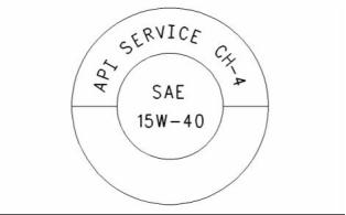

SEBU8337
51
Maintenance Section
Refill Capacities
Three new engine tests were developed for the API
CH-4 oil. The first test specifically evaluates deposits
on pistons for engines with the two-piece steel piston.
This test (piston deposit) also measures the control
of oil consumption. A second test is conducted
with moderate oil soot. The second test measures
the following criteria: wear of piston rings, wear of
cylinder liners, and resistance to corrosion. A third
new test measures the following characteristics with
high levels of soot in the oil: wear of the valve train,
resistance of the oil in plugging the oil filter, and
control of sludge.
In addition to the new tests, API CH-4 oils have
tougher limits for viscosity control in applications that
generate high soot. The oils also have improved
oxidation resistance. API CH-4 oils must pass an
additional test (piston deposit) for engines that use
aluminum pistons (single piece). Oil performance is
also established for engines that operate in areas
with high sulfur diesel fuel.
g00799818
Illustration 19
(Y) TBN by “ASTM D2896”
(X) Percentage of fuel sulfur by weight
(1) TBN of new oil
(2) Change the oil when the TBN deteriorates to 50 percent of
the original TBN.
Use the following guidelines for fuel sulfur levels that
exceed 1.5 percent:
All of these improvements allow the API CH-4
oil to achieve optimum oil change intervals. API
CH-4 oils are recommended for use in extended oil
change intervals. API CH-4 oils are recommended
for conditions that demand a premium oil. Your
Perkins dealer or your Perkins distributor has specific
guidelines for optimizing oil change intervals.
•
•
Choose an oil with the highest TBN that meets one
of these classifications: EMA DHD-1 and API CH-4.
Reduce the oil change interval. Base the oil
change interval on the oil analysis. Ensure that the
oil analysis includes the condition of the oil and a
wear metal analysis.
Some commercial oils that meet the API
classifications may require reduced oil change
intervals. To determine the oil change interval, closely
monitor the condition of the oil and perform a wear
metal analysis.
Excessive piston deposits can be produced by an oil
with a high TBN. These deposits can lead to a loss
of control of the oil consumption and to the polishing
of the cylinder bore.
NOTICE
Failure to follow these oil recommendations can cause
shortened engine service life due to deposits and/or
excessive wear.
NOTICE
Operating Direct Injection (DI) diesel engines with fuel
sulphur levels over 0.5 percent will require shortened
oil change intervals in order to help maintain adequate
wear protection.
Total Base Number (TBN) and Fuel Sulfur
Levels for Direct Injection (DI) Diesel
Engines
Table 18
Percentage of Sulfur in
the fuel
Oil change interval
The Total Base Number (TBN) for an oil depends on
the fuel sulfur level. For direct injection engines that
use distillate fuel, the minimum TBN of the new oil
must be 10 times the fuel sulfur level. The TBN is
defined by “ASTM D2896”. The minimum TBN of the
oil is 5 regardless of fuel sulfur level. Illustration 19
demonstrates the TBN.
Lower than 0.5
0.5 to 1.0
Normal
0.75 of normal
0.50 of normal
Greater than 1.0
Lubricant Viscosity Recommendations
for Direct Injection (DI) Diesel Engines
The correct SAE viscosity grade of oil is determined
by the minimum ambient temperature during
cold engine start-up, and the maximum ambient
temperature during engine operation.
This document has been printed from SPI². Not for Resale
![]()
![]()
![]()
![]()
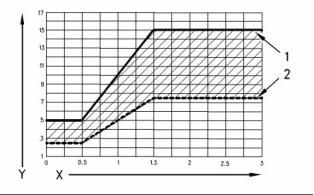
![]()
![]()

52
SEBU8337
Maintenance Section
Refill Capacities
Refer to Table 19 (minimum temperature) in order
to determine the required oil viscosity for starting a
cold engine.
Re-refined Base Stock Oils
Re-refined base stock oils are accept, able for
use in Perkins engines if these oils meet the
performance requirements that are specified by
Perkins. Re-refined base stock oils can be used
exclusively in finished oil or in a combination with
new base stock oils. The US military specifications
and the specifications of other heavy equipment
manufacturers also allow the use of re-refined base
stock oils that meet the same criteria.
Refer to Table 19 (maximum temperature) in order
to select the oil viscosity for engine operation at the
highest ambient temperature that is anticipated.
Generally, use the highest oil viscosity that is
available to meet the requirement for the temperature
at start-up.
Table 19
The process that is used to make re-refined base
stock oil should adequately remove all wear metals
that are in the used oil and all the additives that
are in the used oil. The process that is used to
make re-refined base stock oil generally involves the
process of vacuum distillation and hydrotreating the
used oil. Filtering is adequate for the production of
high quality, re-refined base stock oil.
Engine Oil Viscosity
EMA LRG-1
API CH-4
Viscosity Grade
Ambient Temperature
Minimum
Maximum
SAE 0W20
SAE 0W30
SAE 0W40
SAE 5W30
SAE 5W40
SAE 10W30
SAE 15W40
−40 °C (−40 °F)
−40 °C (−40 °F)
−40 °C (−40 °F)
−30 °C (−22 °F)
−30 °C (−22 °F)
−20 °C (−4 °F)
−10 °C (14 °F)
10 °C (50 °F)
30 °C (86 °F)
40 °C (104 °F)
30 °C (86 °F)
40 °C (104 °F)
40 °C (104 °F)
50 °C (122 °F)
Lubricants for Cold Weather
When an engine is started and an engine is operated
in ambient temperatures below −20 °C (−4 °F), use
multigrade oils that are capable of flowing in low
temperatures.
These oils have lubricant viscosity grades of SAE
0W or SAE 5W.
Synthetic Base Stock Oils
When an engine is started and operated in ambient
temperatures below −30 °C (−22 °F), use a synthetic
base stock multigrade oil with an 0W viscosity grade
or with a 5W viscosity grade. Use an oil with a pour
point that is lower than −50 °C (−58 °F).
Synthetic base oils are acceptable for use in
these engines if these oils meet the performance
requirements that are specified for the engine.
Synthetic base oils generally perform better than
conventional oils in the following two areas:
The number of acceptable lubricants is limited in
cold weather conditions. Perkins recommends the
following lubricants for use in cold weather conditions:
• Synthetic base oils have improved flow at low
temperatures especially in arctic conditions.
First Choice – Use oil with an EMA DHD-1
Recommended Guideline. Use a CH-4 oil that has
an API license. The oil should be either SAE 0W20,
SAE 0W30, SAE 0W40, SAE 5W30, or SAE 5W40
lubricant viscosity grade.
• Synthetic base oils have improved oxidation
stability especially at high operating temperatures.
Some synthetic base oils have performance
characteristics that enhance the service life of the
oil. Perkins does not recommend the automatic
extending of the oil change intervals for any type of
oil.
Second Choice – Use an oil that has a CH-4
additive package. Although the oil has not been
tested for the requirements of the API license, the oil
must be either SAE 0W20, SAE 0W30, SAE 0W40,
SAE 5W30, or SAE 5W40.
NOTICE
Shortened engine service life could result if second
choice oils are used.
This document has been printed from SPI². Not for Resale
![]()

![]()
![]()
SEBU8337
53
Maintenance Section
Refill Capacities
Aftermarket Oil Additives
• Tests are conducted in order to detect
contamination of the oil by water, glycol or fuel.
Perkins does not recommend the use of aftermarket
additives in oil. It is not necessary to use aftermarket
additives in order to achieve the engine’s maximum
service life or rated performance. Fully formulated,
finished oils consist of base oils and of commercial
additive packages. These additive packages are
blended into the base oils at precise percentages in
order to help provide finished oils with performance
characteristics that meet industry standards.
• The Oil Condition Analysis determines the loss of
the oil’s lubricating properties. An infrared analysis
is used to compare the properties of new oil to the
properties of the used oil sample. This analysis
allows technicians to determine the amount of
deterioration of the oil during use. This analysis
also allows technicians to verify the performance
of the oil according to the specification during the
entire oil change interval.
There are no industry standard tests that evaluate
the performance or the compatibility of aftermarket
additives in finished oil. Aftermarket additives may
not be compatible with the finished oil’s additive
package, which could lower the performance of the
finished oil. The aftermarket additive could fail to
mix with the finished oil. This could produce sludge
in the crankcase. Perkins discourages the use of
aftermarket additives in finished oils.
To achieve the best performance from a Perkins
engine, conform to the following guidelines:
• Select the correct oil, or a commercial oil that meets
the “EMA Recommended Guideline on Diesel
Engine Oil” or the recommended API classification.
• See the appropriate “Lubricant Viscosities” table in
order to find the correct oil viscosity grade for your
engine.
• At the specified interval, service the engine. Use
new oil and install a new oil filter.
• Perform maintenance at the intervals that are
specified in the Operation and Maintenance
Manual, “Maintenance Interval Schedule”.
Oil analysis
Some engines may be equipped with an oil sampling
valve. If oil analysis is required the oil sampling valve
is used to obtain samples of the engine oil. The oil
analysis will complement the preventive maintenance
program.
The oil analysis is a diagnostic tool that is used to
determine oil performance and component wear
rates. Contamination can be identified and measured
through the use of the oil analysis. The oil analysis
includes the following tests:
• The Wear Rate Analysis monitors the wear of the
engine’s metals. The amount of wear metal and
type of wear metal that is in the oil is analyzed. The
increase in the rate of engine wear metal in the
oil is as important as the quantity of engine wear
metal in the oil.
This document has been printed from SPI². Not for Resale
![]()
54
SEBU8337
Maintenance Section
Maintenance Interval Schedule
i02784638
Every 2000 Service Hours
Maintenance Interval Schedule
Alternator - Inspect ............................................... 55
Water Pump - Inspect ........................................... 81
Every 3000 Service Hours or 2 Years
When Required
Cooling System Water Temperature Regulator -
Replace ............................................................... 60
Crankshaft Vibration Damper - Inspect ................. 61
Engine Protective Devices - Check ...................... 70
Engine Speed/Timing Sensors - Check/Clean/
Calibrate .............................................................. 70
Turbocharger - Inspect .......................................... 79
Battery - Replace .................................................. 55
Battery or Battery Cable - Disconnect .................. 56
Engine - Clean ...................................................... 62
Engine Oil Sample - Obtain .................................. 67
Fuel System - Prime ............................................. 71
Severe Service Application - Check ..................... 78
Daily
Every 5000 Service Hours
Cooling System Coolant Level - Check ................ 60
Driven Equipment - Check .................................... 61
Engine Air Cleaner Service Indicator - Inspect ..... 64
Engine Oil Level - Check ...................................... 66
Fuel System Primary Filter/Water Separator -
Starting Motor - Inspect ........................................ 79
Every 6000 Service Hours
Overhaul Considerations ...................................... 77
Drain ................................................................... 72
Walk-Around Inspection ........................................ 80
Every 6000 Service Hours or 3 Years
Cooling System Coolant (ELC) - Change ............. 58
Every Week
Every 12 000 Service Hours or 6 Years
Jacket Water Heater - Check ................................ 77
Overhaul Considerations ...................................... 77
Every 250 Service Hours or 1 Year
Battery Electrolyte Level - Check .......................... 56
Fuel Tank Water and Sediment - Drain ................. 76
Initial 500 Service Hours
Engine Valve Lash - Inspect/Adjust ...................... 71
Every 500 Service Hours
Belts - Inspect/Adjust/Replace .............................. 57
Engine Valve Lash - Inspect/Adjust ...................... 71
Every 500 Service Hours or 1 Year
Aftercooler Core - Clean/Test ............................... 55
Engine Air Cleaner Element (Single Element) -
Inspect/Replace .................................................. 62
Engine Crankcase Breather - Replace ................. 64
Engine Mounts - Inspect ....................................... 66
Engine Oil and Filter - Change ............................. 68
Fan Drive Bearing - Lubricate ............................... 71
Fuel System Primary Filter (Water Separator)
Element - Replace .............................................. 73
Fuel System Secondary Filter - Replace .............. 74
Hoses and Clamps - Inspect/Replace .................. 76
Radiator - Clean .................................................... 78
Every 1000 Service Hours or 1 Year
Electronic Unit Injector - Inspect/Adjust ................ 61
This document has been printed from SPI². Not for Resale
![]()

SEBU8337
55
Maintenance Section
Aftercooler Core - Clean/Test
i02578388
i02322311
Aftercooler Core - Clean/Test
(Air-To-Air Aftercooler)
Alternator - Inspect
Perkins recommends a scheduled inspection of
the alternator. Inspect the alternator for loose
connections and correct battery charging. Check the
ammeter (if equipped) during engine operation in
order to ensure correct battery performance and/or
correct performance of the electrical system. Make
repairs, as required.
Note: Adjust the frequency of cleaning according to
the effects of the operating environment.
Inspect the cooling air side of the aftercooler for these
items: damaged fins, corrosion, dirt, grease, insects,
leaves, oil, and other debris. Clean the cooling air
side of the aftercooler, if necessary.
Check the alternator and the battery charger for
correct operation. If the batteries are correctly
charged, the ammeter reading should be very near
zero. All batteries should be kept charged. The
batteries should be kept warm because temperature
affects the cranking power. If the battery is too cold,
the battery will not crank the engine. When the
engine is not run for long periods of time or if the
engine is run for short periods, the batteries may not
fully charge. A battery with a low charge will freeze
more easily than a battery with a full charge.
For air-to-air aftercoolers, use the same methods that
are used for cleaning the outside of radiators.
Personal injury can result from air pressure.
Personal injury can result without following prop-
er procedure. When using pressure air, wear a pro-
tective face shield and protective clothing.
i01878164
Maximum air pressure at the nozzle must be less
than 205 kPa (30 psi) for cleaning purposes.
Battery - Replace
Pressurized air is the preferred method for removing
loose debris. Hold the nozzle approximately 6 mm
(0.25 inch) away from the fins. Slowly move the air
nozzle in a direction that is parallel with the tubes.
This will remove debris that is between the tubes.
Batteries give off combustible gases which can
explode. A spark can cause the combustible gas-
es to ignite. This can result in severe personal in-
jury or death.
Pressurized water may also be used for cleaning.
The maximum water pressure for cleaning purposes
must be less than 275 kPa (40 psi). Use pressurized
water in order to soften mud.
Ensure proper ventilation for batteries that are in
an enclosure. Follow the proper procedures in or-
der to help prevent electrical arcs and/or sparks
near batteries. Do not smoke when batteries are
serviced.
Use a degreaser and steam for removal of oil and
grease. Wash the core with detergent and hot water.
Thoroughly rinse the core with clean water.
After cleaning, start the engine. Run the engine for
two minutes. This will help in the removal of debris
and drying of the core. Stop the engine. Inspect
the core for cleanliness. Repeat the cleaning, if
necessary.
The battery cables or the batteries should not be
removed with the battery cover in place. The bat-
tery cover should be removed before any servic-
ing is attempted.
Inspect the fins for damage. Bent fins may be opened
with a “comb”.
Removing the battery cables or the batteries with
the cover in place may cause a battery explosion
resulting in personal injury.
Inspect these items for good condition: welds,
mounting brackets, air lines, connections, clamps,
and seals. Make repairs, if necessary.
1. Switch the engine to the OFF position. Remove
all electrical loads.
This document has been printed from SPI². Not for Resale
![]()
![]()
![]()
![]()
![]()
![]()
![]()
56
SEBU8337
Maintenance Section
Battery Electrolyte Level - Check
2. Turn off any battery chargers. Disconnect any
battery chargers.
2. Check the condition of the electrolyte with a
suitable battery tester.
3. Install the caps.
3. The NEGATIVE “-” cable connects the NEGATIVE
“-” battery terminal to the NEGATIVE “-” terminal
on the starter motor. Disconnect the cable from
the NEGATIVE “-” battery terminal.
4. Keep the batteries clean.
Clean the battery case with one of the following
cleaning solutions:
4. The POSITIVE “+” cable connects the POSITIVE
“+” battery terminal to the POSITIVE “+” terminal
on the starting motor. Disconnect the cable from
the POSITIVE “+” battery terminal.
• A mixture of 0.1 kg (0.2 lb) of washing soda or
baking soda and 1 L (1 qt) of clean water
Note: Always recycle a battery. Never discard a
battery. Return used batteries to an appropriate
recycling facility.
• A mixture of 0.1 L (0.11 qt) of ammonia and 1 L
(1 qt) of clean water
Thoroughly rinse the battery case with clean water.
5. Remove the used battery.
6. Install the new battery.
Use a fine grade of sandpaper to clean the
terminals and the cable clamps. Clean the items
until the surfaces are bright or shiny. DO NOT
remove material excessively. Excessive removal
of material can cause the clamps to not fit properly.
Coat the clamps and the terminals with a suitable
petroleum jelly.
Note: Before the cables are connected, ensure that
the engine start switch is OFF.
7. Connect the cable from the starting motor to the
POSITIVE “+” battery terminal.
8. Connect the cable from the NEGATIVE “-” terminal
on the starter motor to the NEGATIVE “-” battery
terminal.
i02857256
Battery or Battery Cable -
Disconnect
i02563861
Battery Electrolyte Level -
Check
The battery cables or the batteries should not be
removed with the battery cover in place. The bat-
tery cover should be removed before any servic-
ing is attempted.
When the engine is not run for long periods of time or
when the engine is run for short periods, the batteries
may not fully recharge. Ensure a full charge in order
to help prevent the battery from freezing. If batteries
are correctly charged, the ammeter reading should
be very near zero, when the engine is in operation.
Removing the battery cables or the batteries with
the cover in place may cause a battery explosion
resulting in personal injury.
1. Turn the start switch to the OFF position. Turn the
ignition switch (if equipped) to the OFF position
and remove the key and all electrical loads.
All lead-acid batteries contain sulfuric acid which
can burn the skin and clothing. Always wear a face
shield and protective clothing when working on or
near batteries.
2. Turnoff any battery chargers. Disconnect any
battery chargers.
3. Disconnect the negative battery terminal at the
battery that goes to the start switch. Ensure that
the cable cannot contact the terminal. When four
12 volt batteries are involved, the negative side of
two batteries must be disconnected.
1. Remove the filler caps. Maintain the electrolyte
level to the “FULL” mark on the battery.
If the addition of water is necessary, use distilled
water. If distilled water is not available use clean
water that is low in minerals. Do not use artificially
softened water.
4. Tape the leads in order to help prevent accidental
starting.
This document has been printed from SPI². Not for Resale
![]()
![]()
![]()
![]()
![]()
SEBU8337
57
Maintenance Section
Belts - Inspect/Adjust/Replace
5. Proceed with necessary system repairs. Reverse
the steps in order to reconnect all of the cables.
Alternator Belt Adjustment
i02784753
Belts - Inspect/Adjust/Replace
Inspection
Inspect the alternator belt and the fan drive belts for
wear and for cracking. Replace the belts if the belts
are not in good condition.
Check the belt tension according to the information
in Systems Operation, Testing and Adjusting, “Belt
Tension Chart”.
Slippage of loose belts can reduce the efficiency
of the driven components. Vibration of loose belts
can cause unnecessary wear on the following
components:
• Belts
• Pulleys
• Bearings
If the belts are too tight, unnecessary stress is placed
on the components. This reduces the service life of
the components.
Replacement
g01391209
Illustration 20
For applications that require multiple drive belts,
replace the drive belts in matched sets. Replacing
one drive belt of a matched set will cause the new
drive belt to carry more load because the older drive
belts are stretched. The additional load on the new
drive belt could cause the new drive belt to fail.
1. Remove the belt guard.
2. Loosen alternator pivot bolt (2) .
3. Loosen the setscrew for the adjustment link (1).
4. Move the assembly in order to increase or
decrease the belt tension. Refer to Systems
Operation, Testing and Adjusting, “Belt Tension
Chart”.
5. Tighten the setscrew for the adjustment link (1)
securely. Tighten alternator pivot bolt (2) securely.
6. Reinstall the belt guard.
If new alternator belts are installed, check the
tension of the alternator belt again after 10
minutes of engine operation at the rated rpm.
7. Remove the belt guard and check the belt tension.
When the correct belt tension is obtained, fit the
belt guard.
This document has been printed from SPI². Not for Resale
![]()
![]()

58
SEBU8337
Maintenance Section
Cooling System Coolant (ELC) - Change
Adjustment of the Fan Drive Belt
i02579635
Cooling System Coolant (ELC)
- Change
NOTICE
Care must be taken to ensure that fluids are contained
during performance of inspection, maintenance, test-
ing, adjusting and repair of the product. Be prepared to
collect the fluid with suitable containers before open-
ing any compartment or disassembling any compo-
nent containing fluids.
Dispose of all fluids according to Local regulations and
mandates.
NOTICE
Keep all parts clean from contaminants.
Contaminants may cause rapid wear and shortened
component life.
Clean the cooling system and flush the cooling
system before the recommended maintenance
interval if the following conditions exist:
g01402065
Illustration 21
• The engine overheats frequently.
• Foaming of the coolant is observed.
1. Remove the belt guard.
2. Loosen the large locknut (3) and turn the
adjustment screw (4) until the correct belt tension
is obtained.
• The oil has entered the cooling system and the
coolant is contaminated.
• The fuel has entered the cooling system and the
coolant is contaminated.
3. Tighten the large locknut (3) securely and recheck
the belt tension.
Note: When the cooling system is cleaned, only
clean water is needed when the ELC is drained and
replaced.
4. If the belt tension is correct, loosen the adjustment
screw (3) in order to release the tension.
5. Reinstall the belt guard.
Note: Inspect the water pump and the water
temperature regulator after the cooling system has
been drained. This is a good opportunity to replace
the water pump, the water temperature regulator and
the hoses, if necessary.
If new alternator belts are installed, check the
tension of the alternator belt again after 10
minutes of engine operation at the rated rpm.
6. Remove the belt guard and check the belt tension.
When the correct belt tension is obtained, fit the
belt guard.
Drain
Pressurized System: Hot coolant can cause seri-
ous burns. To open the cooling system filler cap,
stop the engine and wait until the cooling system
components are cool. Loosen the cooling system
pressure cap slowly in order to relieve the pres-
sure.
This document has been printed from SPI². Not for Resale
![]()
![]()
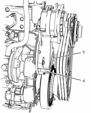
![]()
![]()
![]()
![]()
![]()
![]()
![]()
SEBU8337
59
Maintenance Section
Cooling System Coolant (ELC) - Change
1. Stop the engine and allow the engine to cool.
Loosen the cooling system filler cap slowly in
order to relieve any pressure. Remove the cooling
system filler cap.
NOTICE
Do not fill the cooling system faster than 5 L
(1.3 US gal) per minute to avoid air locks.
2. Open the drain cock or remove the drain plug on
the radiator.
Cooling system air locks may result in engine damage.
2. Fill the cooling system with Extended Life
Coolant (ELC). Refer to the Operation and
Maintenance Manual, “Fluid Recommendations”
topic (Maintenance Section) for more information
on cooling system specifications. Do not install the
cooling system filler cap.
Allow the coolant to drain.
NOTICE
Dispose of used engine coolant or recycle. Various
methods have been proposed to reclaim used coolant
for reuse in engine cooling systems. The full distillation
procedure is the only method acceptable by Perkins to
reclaim the coolant.
3. Start and run the engine for one minute in order
to purge the air from the cavities of the engine
block. Stop the engine.
For information regarding the disposal and the
recycling of used coolant, consult your Perkins dealer
or your Perkins distributor.
4. Check the coolant level. Maintain the coolant
level within 13 mm (0.5 inch) below the bottom
of the pipe for filling. If necessary, repeat step 3.
Maintain the coolant level in the expansion bottle
(if equipped) at the correct level.
Flush
1. Flush the cooling system with clean water in order
to remove any debris.
2. Close the drain cock or install the drain plug on
the radiator.
NOTICE
Do not fill the cooling system faster than 5 L
(1.3 US gal) per minute to avoid air locks.
Cooling system air locks may result in engine damage.
3. Fill the cooling system with clean water. Install the
cooling system filler cap.
g00103639
Illustration 22
4. Start and run the engine until the water
temperature regulator opens and the fluid levels
decreases in the header tank.
Filler cap
5. Clean the cooling system filler cap and inspect the
gasket. If the gasket is damaged, discard the old
filler cap and install a new filler cap. If the gasket
is not damaged, use a suitable pressurizing pump
in order to pressure test the filler cap. The correct
pressure is stamped on the face of the filler cap. If
the filler cap does not retain the correct pressure,
install a new filler cap.
5. Stop the engine and allow the engine to cool.
Loosen the cooling system filler cap slowly in
order to relieve any pressure. Remove the cooling
system filler cap. Open the drain cock or remove
the drain plug on the radiator. Allow the water to
drain. Flush the cooling system with clean water.
6. Start the engine. Inspect the cooling system for
leaks and for correct operating temperature.
Fill
1. Close the drain cock or install the drain plug on
the radiator.
This document has been printed from SPI². Not for Resale
![]()
![]()
![]()
![]()
![]()
![]()
![]()
![]()
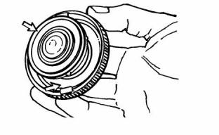
![]()
60
SEBU8337
Maintenance Section
Cooling System Coolant Level - Check
i01197583
3. Clean the cooling system filler cap and check the
condition of the filler cap gaskets. Replace the
cooling system filler cap if the filler cap gaskets are
damaged. Reinstall the cooling system filler cap.
Cooling System Coolant Level
- Check
4. Inspect the cooling system for leaks.
Check the coolant level when the engine is stopped
and cool.
i02573904
Cooling System Water
Temperature Regulator -
Replace
Replace the water temperature regulator before
the water temperature regulator fails. This is a
recommended preventive maintenance practice.
Replacing the water temperature regulator reduces
the chances for unscheduled downtime.
A water temperature regulator that fails in a
partially opened position can cause overheating or
overcooling of the engine.
g00285520
Illustration 23
Cooling system filler cap
A water temperature regulator that fails in the closed
position can cause excessive overheating. Excessive
overheating could result in cracking of the cylinder
head or piston seizure problems.
Pressurized System: Hot coolant can cause seri-
ous burns. To open the cooling system filler cap,
stop the engine and wait until the cooling system
components are cool. Loosen the cooling system
pressure cap slowly in order to relieve the pres-
sure.
A water temperature regulator that fails in the open
position will cause the engine operating temperature
to be too low during partial load operation. Low
engine operating temperatures during partial loads
could cause an excessive carbon buildup inside the
cylinders. This excessive carbon buildup could result
in an accelerated wear of the piston rings and wear
of the cylinder liner.
1. Remove the cooling system filler cap slowly in
order to relieve pressure.
2. Maintain the coolant level within 13 mm (0.5 inch)
of the bottom of the filler pipe. If the engine is
equipped with a sight glass, maintain the coolant
level to the proper level in the sight glass.
Refer to Disassembly and Assembly, “Water
Temperature Regulator Housing - Remove and
Install” for the replacement procedure of the water
temperature regulator, or consult your Perkins
distributor.
Note: If only the water temperature regulators are
replaced, drain the coolant from the cooling system to
a level that is below the water temperature regulator
housing.
g00103639
Illustration 24
Typical filler cap gaskets
This document has been printed from SPI². Not for Resale
![]()
![]()

![]()
![]()
![]()
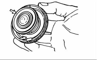
SEBU8337
61
Maintenance Section
Crankshaft Vibration Damper - Inspect
i02573905
i02151646
Crankshaft Vibration Damper
- Inspect
Driven Equipment - Check
Refer to the OEM specifications for more information
on the following maintenance recommendations for
the driven equipment:
Damage to the crankshaft vibration damper or failure
of the crankshaft vibration damper can increase
torsional vibrations. This can result in damage to
the crankshaft and to other engine components. A
damper that is damaged can cause excessive gear
train noise at variable points in the speed range.
• Inspection
• Adjustment
• Lubrication
The damper is mounted to the crankshaft which is
located behind the belt guard on the front of the
engine.
• Other maintenance recommendations
Perform any maintenance for the driven equipment
which is recommended by the OEM.
Visconic Damper
The visconic damper has a weight that is located
inside a fluid filled case. The weight moves in the
case in order to limit torsional vibration.
i02784833
Electronic Unit Injector -
Inspect/Adjust
Inspect the damper for evidence of fluid leaks. If
a fluid leak is found, determine the type of fluid.
The fluid in the damper is silicone. Silicone has the
following characteristics: transparent, viscous, and
smooth.
If the fluid leak is oil, inspect the crankshaft seals for
leaks. If a leak is observed, replace the crankshaft
seals.
Be sure the engine cannot be started while this
maintenance is being performed. To prevent pos-
sible injury, do not use the starting motor to turn
the flywheel.
Inspect the damper and repair or replace the damper
for any of the following reasons:
Hot engine components can cause burns. Allow
additional time for the engine to cool before mea-
suring/adjusting the unit injectors.
• The damper is dented, cracked, or leaking.
• The paint on the damper is discolored from heat.
The electronic unit injectors use high voltage. Dis-
connect the unit injector enable circuit connector
in order to prevent personal injury. Do not come
in contact with the injector terminals while the en-
gine is running.
• The engine has had a failure because of a broken
crankshaft.
• Analysis of the oil has revealed that the front main
bearing is badly worn.
• There is a large amount of gear train wear that is
not caused by a lack of oil.
The operation of Perkins engines with improper
adjustments of the electronic unit injector can reduce
engine efficiency. This reduced efficiency could result
in excessive fuel usage and/or shortened engine
component life.
• The temperature of the damper fluid is too high.
Refer to the Service Manual or consult your Perkins
distributor for information about damper replacement.
Only qualified service personnel should perform
this maintenance. Refer to the following topics
for your engine for the correct procedure: Refer
to the Systems Operation, Testing and Adjusting,
“Electronic Unit Injector - Test” for the test procedure,
and Systems Operation, Testing and Adjusting,
“Electronic Unit Injector - Adjust” for the correct
procedure for adjusting the injectors.
This document has been printed from SPI². Not for Resale
![]()
![]()
![]()