 English
 Espaol
 Franais
 阿拉伯
阿拉伯 中文
中文 Deutsch
 Italiano
 Português
 日本
日本 韩国
韩国 български
 hrvatski
 esky
esky Dansk
Dansk Nederlands
 suomi
suomi Ελληνικ
 印度
印度 norsk
norsk Polski
 Roman
Roman русский
 Svenska
珀金斯Perkins1600发动机故障维修排除资料手册,珀金斯Perkins1600发动机故障维修排除资料手册技术支持中心,珀金斯Perkins1600发动机故障维修排除资料手册代理商,珀金斯Perkins1600发动机故障维修排除资料手册销售服务中心,珀金斯Perkins1600发动机故障维修排除资料手册价格规格资料查询,宁波日昕动力科技有限公司

产品中心
珀金斯Perkins1600发动机故障维修排除资料手册
详细描述
Troubleshooting
1600 Series Industrial Engine
Electrical Connector - Inspect
Most electrical faults are caused by poor connections.
The following procedure will assist in detecting faults
with connectors and with wiring. If a fault is found,
correct the condition and verify that the fault is
resolved.
Intermittent electrical faults are sometimes resolved
by disconnecting and reconnecting connectors. It is
very important to check for diagnostic codes
immediately before disconnecting a connector. Also
check for diagnostic codes after reconnecting the
connector. If the status of a diagnostic code is
changed due to disconnecting and reconnecting a
connector, there are several possible reasons. The
likely reasons are loose terminals, improperly
crimped terminals, moisture, corrosion, and
inadequate mating of a connection.
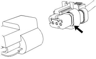
Illustration 30
g01131019
Seal for a three-pin connector (typical example)
Follow these guidelines:
• Always use a breakout harness for a voltmeter
probe or a test light. Never break the insulation of a
wire in order to access a circuit for measurements.
• If a wire is cut, always install a new terminal for the
repair.
The connection of any electrical equipment and
the disconnection of any electrical equipment
may cause an explosion hazard which may result
in injury or death. Do not connect any electrical
equipment or disconnect any electrical equipment
in an explosive atmosphere.
This document has been printed from SPI2. NOT FOR RESALE.

![]()
![]()
![]()
![]()
![]()
116
KENR8774
Diagnostic Functional Tests
Table 49
TroubleshootingTest Steps
Values
Results
1. Check Connectors for Moisture and Corrosion
Harness,
connectors,
and seals are
OK.
Result: A fault has been found with the harness or the
connectors.
A. Inspect all the harnesses. Ensure that the routing of the wiring
harness allows the wires to enter the face of each connector at a
perpendicular angle. Otherwise, the wire will deform the seal bore.
This will create a path for the entrance of moisture. Verify that the
seals for the wires are sealing correctly.
Repair the connectors or the wiring, as required. Ensure that
all of the seals are correctly installed. Ensure that the con-
nectors have been reattached.
If corrosion is evident on the pins, sockets or the connector,
use only denatured alcohol to remove the corrosion. Use a
cotton swab or a soft brush to remove the corrosion.
If moisture was found in the connectors, run the engine for
several minutes and check again for moisture. If moisture re-
appears, the moisture is wicking into the connector. Even if
the moisture entry path is repaired, it may be necessary to re-
place the wires.
Use the electronic service tool in order to clear all logged di-
agnostic codes and then verify that the repair eliminates the
fault.
Result: The harness, connectors, and seals are in good
condition.
B. Ensure that the sealing plugs are in place. If any of the plugs are
missing, replace the plug. Ensure that the plugs are inserted cor-
rectly into the connector.
C. Disconnect the suspect connector and inspect the connector
seal. Ensure that the seal is in good condition. If necessary, replace
the connector.
D. Thoroughly inspect the connectors for evidence of moisture
entry.
Note: It is normal to see some minor seal abrasion on connector
seals. Minor seal abrasion will not allow the entry of moisture.
If moisture or corrosion is evident in the connector, the source of
the moisture entry must be found and the source of the moisture
entry must be repaired. If the source of the moisture entry is not re-
paired, the fault will recur. Simply drying the connector will not recti-
fy the fault. Check the following items for the possible moisture
entry path:
Proceed to Test Step 2.
· Missing seals
· Incorrectly installed seals
· Nicks in exposed insulation
· Improperly mated connectors
Moisture can also travel to a connector through the inside of a wire.
If moisture is found in a connector, thoroughly check the connector
harness for damage. Also check other connectors that share the
harness for moisture.
Note: The ECM is a sealed unit. If moisture is found in an ECM
connector, the ECM is not the source of the moisture. Do not re-
place the ECM.
2. Check the Wires for Damage to the Insulation
The wiring is Result: There is damage to the harness.
OK
A. Carefully inspect each wire for signs of abrasion, nicks, and
cuts.
Inspect the wires for the following conditions:
· Exposed insulation
Repair the wires or replace the wires, as required.
Use the electronic service tool in order to clear all logged di-
agnostic codes and then verify that the repair eliminates the
fault.
· Rubbing of a wire against the engine
· Rubbing of a wire against a sharp edge
Result: The wires are free of abrasion, nicks, and cuts and
the harness is correctly clamped.
B. Check all of the fasteners for the harness and the strain relief
components on the ECM in order to verify that the harness is cor-
rectly secured. Also check all of the fasteners in order to verify that
the harness is not compressed. Pull back the harness sleeves in
order to check for a flattened portion of wire. A fastener that has
been overtightened flattens the harness. This damages the wires
that are inside the harness.
Proceed to Test Step 3.
3. Inspect the Connector Terminals
Terminals are Result: The terminals of the connector are damaged.
aligned and
undamaged
Repair the terminals and/or replace the terminals, as
required.
(continued)
This document has been printed from SPI2. NOT FOR RESALE.

![]()
KENR8774
117
Diagnostic Functional Tests
(Table 49, contd)
TroubleshootingTest Steps
Values
Results
A. Visually inspect each terminal in the connector. Verify that the
terminals are not damaged. Verify that the terminals are correctly
aligned in the connector and verify that the terminals are correctly
located in the connector.
Use the electronic service tool in order to clear all logged di-
agnostic codes and then verify that the repair eliminates the
fault.
Result: The terminals are OK.
Proceed to Test Step 4.
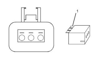
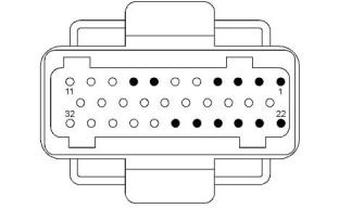
Illustration 31
g01802454
A typical example of the lock wedge.
(1) Lock wedge
Table 50
TroubleshootingTest Steps
Values
Results
4. Perform a Pull Test on Each Wire Terminal Connection
Pull test OK Result: A wire has been pulled from a terminal or a terminal
has been pulled from the connector in the 45 N (10 lb) pull
test.
A. Ensure that the locking wedge for the connector is installed cor-
rectly. Terminals cannot be retained inside the connector if the lock-
ing wedge is not installed correctly.
Replace the terminal. Replace damaged connectors, as
required.
B. Perform the 45 N (10 lb) pull test on each wire. Each terminal
and each connector should easily withstand 45 N (10 lb) of tension
and each wire should remain in the connector body. This test
checks whether the wire was correctly crimped in the terminal and
whether the terminal was correctly inserted into the connector.
Use the electronic service tool in order to clear all logged di-
agnostic codes and then verify that the repair eliminates the
fault.
Result: All terminals pass the pull test.
Proceed to Test Step 5.
5. Check Individual Pin Retention into the Socket
The sockets Result: Terminals are damaged.
provide good
A. Verify that the sockets provide good retention for the pins. Insert retention for Replace the damaged terminals. Verify that the repair elimi-
a new pin into each socket one at a time in order to check for a
good grip on the pin by the socket.
the new pin. nates the problem.
Use the electronic service tool in order to clear all logged di-
agnostic codes and then verify that the repair eliminates the
fault.
Result: The terminals are OK.
Proceed to Test Step 6.
(continued)
This document has been printed from SPI2. NOT FOR RESALE.

![]()
![]()
![]()
118
KENR8774
Diagnostic Functional Tests
(Table 50, contd)
TroubleshootingTest Steps
Values
Results
6. Check the Locking Mechanism of the Connectors
The connec- Result: The locking mechanism for the connector is dam-
tors are
A. Ensure that the connectors lock correctly. After locking the con- locked and
aged or missing.
nectors, ensure that the two halves cannot be pulled apart.
are not
damaged
Repair the connector or replace the connector, as required.
Use the electronic service tool in order to clear all logged di-
agnostic codes and then verify that the repair eliminates the
fault.
B. Verify that the latch tab of the connector is correctly latched. Also
verify that the latch tab of the connector returns to the locked
position.
Result: The connectors are in good condition.
Proceed to Test Step 7.
8. Perform the “Continuous Monitor” on the Electronic Serv-
ice Tool
Intermittent
faults were
indicated.
Result: No intermittentfaults were found.
If you were sent from another procedure, return to the proce-
dure and continue testing. If this test confirms that the fault
has been eliminated, return the engine to service.
A. Run the “Continuous Monitor” test using the electronic service
tool. Refer to Troubleshooting, “Electronic Service Tools”.
B. Wiggle the wiring harness in order to reproduce intermittent
faults.
Result: At least one intermittent fault was indicated.
Repair the harness or the connector.
If an intermittent fault exists, the status will be highlighted.
Use the electronic service tool in order to clear all logged di-
agnostic codes and then verify that the repair eliminates the
fault.
i05527710
Electrical Power Supply - Test
(Electronic Control Module)
This procedure tests that the correct voltage is being
supplied to the Electronic Control Module (ECM).
This procedure covers the following codes:
Table 51
Diagnostic Trouble Codes
DTC
Code Description
Comments
Electrical system voltage B+ out-of- DTC 112 is set when the Electronic Control Module (ECM) detects an alternator output
range high greater than 32 Vat pin X3:3 for more than 0.5 seconds.
112
Electrical system voltage B+ out-of- DTC 113 is set when the ECM detects less than 10.3 Vat pin X3:3 for more than 0.5
113
626
range low
seconds.
DTC 626 is set when power is interrupted to the ECM. Loose or dirty connections at
fuses, relay connections, and battery or ground cables can cause the ECM to power
down.
Unexpected Reset Fault
Follow the troubleshooting procedure in order to identify the root cause of the fault.
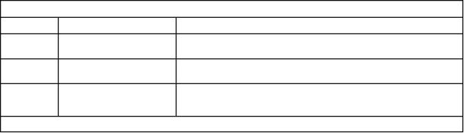
The ECM is grounded to the battery negative terminal
at ECM pins X3:6 and X3:7.
The ECM receives ignition voltage at pin X3:3. The
ignition voltage signals the ECM to provide a ground
path from pin X3:5 to terminal 85 on the main power
relay. Switching the relay provides power from the
battery positive terminal through the fuses and relay
terminals 30 and 87 to ECM pins X4:1 and X4:2.
Fault Detection/Management
This document has been printed from SPI2. NOT FOR RESALE.

![]()
KENR8774
119
Diagnostic Functional Tests
The ECM internally monitors battery voltage. When
the ECM continuously receives less than 10.3 V or
more than 32 V, a DTC will be set.
Illustration 32
g03502100
Schematic diagram for the electrical power supply circuit to the ECM.
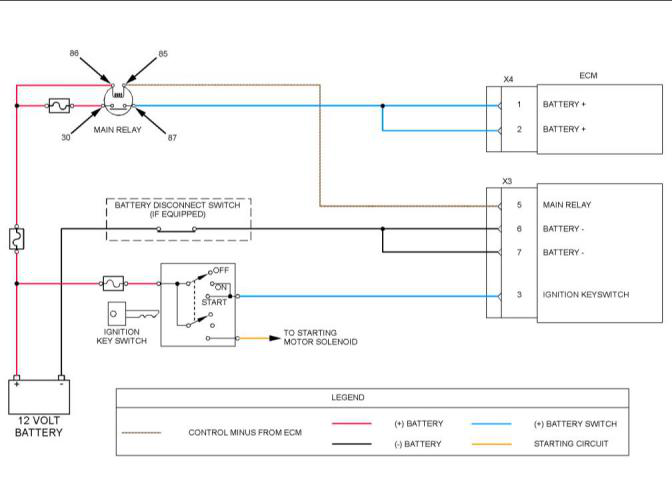
Illustration 33
g03502143
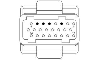
Illustration 34
g03502144
View of the pin locations on the X3 ECM connector
for the ECM power supply
View of the pin locations on the X4 ECM connector
for the ECM power supply
(3) Ignition keyswitch
(5) Main relay
(6) Ground
(1) Battery +
(2) Battery +
(7) Ground
This document has been printed from SPI2. NOT FOR RESALE.
![]()
![]()
![]()
![]()
![]()
![]()
120
KENR8774
Diagnostic Functional Tests
Table 52
Required Tools
Part Description
Relay Breakout Harness
Tool
Part Number
Qty
A
27610378
1
Batteries give off flammable fumes which can
explode.
To avoid injury or death, do not strike a match,
cause a spark, or smoke in the vicinity of a
battery.
Table 53
TroubleshootingTest Steps
Values
Results
1. Inspect Electrical Connectors and Wiring
Damaged wire Result: A damaged wire or damaged connector was found. A
or connector
fuse was blown.
A. Thoroughly inspect the battery connections and the con-
nections to the keyswitch, the main power relay, and the ECM.
Refer to Troubleshooting, “Electrical Connectors - Inspect” for
details.
Repair the damaged wire or the damaged connector. Replace
any blown fuses.
Use the electronic service tool to clear all logged diagnostic co-
des. Verify that the repair eliminates the fault.
B. Check the harness for abrasion and for pinch points from
the battery to the ECM, and from the keyswitch to the ECM.
Result: All connectors, pins, and sockets are correctly con-
nected and/or inserted and the harness is free of corrosion, of
abrasion or of pinch points.
C. Check the fuses.
Proceed to Test Step 2.
2. Check for Active Diagnostic Codes or Logged Diagnos- Diagnostic
Result: None of the diagnostic codes are active or recently
tic Codes
codes
logged.
A. Connect the electronic service tool to the diagnostic
connector.
If the fault is intermittent,refer to Troubleshooting, “Electrical
Connectors - Inspect”.
If the ECM is receiving no battery voltage, proceed to Test Step
3.
B. Turn the keyswitch to the ON position.
C. Check if any of the diagnostic codes listed in Table 51 are
active or recently logged.
Result: At least one of the diagnostic codes is active or re-
cently logged.
Proceed to Test Step 3.
3. Check the Batteries
Battery load test Result: The batteries do not pass the load test. The measured
passed
voltage is less than 21 V.
A. Load-test the batteries. Use a suitable battery load tester.
Refer to Systems Operation, Testing and Adjusting, “Battery -
Test” for the correct procedure.
Recharge or replace the faulty batteries.
Use the electronic service tool in order to clear all logged diag-
nostic codes and then verify that the repair eliminates the fault.
Result: The batteries pass the load test. The measured voltage
is at least 21 V.
Proceed to Test Step 4.
(continued)
This document has been printed from SPI2. NOT FOR RESALE.


![]()
![]()
![]()
KENR8774
121
Diagnostic Functional Tests
(Table 53, contd)
TroubleshootingTest Steps
Values
Results
4. Check for Battery Voltage at the ECM Main Power Relay 21 V to 27 V
Result: The measured voltage is not within the expected
Inputs
range.
A. Turn the keyswitch to the OFF position.
If a fuse is blown, there is a short in the wiring. If a fuse is not
blown, there is an open circuit in the wiring.
B. Connect Tooling A to the main relay and the power distribu-
tion connector.
Repair the harness or replace the harness.
Result: The measured voltage is within the expected range.
C. Turn the keyswitch to the ON position.
Proceed to Test Step 5.
D. Use a multimeter to measure the voltage between the fol-
lowing points:
· Relay terminal 86 and ground
· Relay terminal 30 and ground
E. Turn the keyswitch to the OFF position.
5. Check the Main Relay Signal Voltage at the Relay
0.06 V to 2 V
Result: The measured voltage is within the expected range.
A. Turn the keyswitch to the ON position.
Proceed to Test Step 6.
B. Use a multimeter to measure the voltage between relay ter-
minal 85 and ground.
Result: The measured voltage is not within the expected
range.
Proceed to Test Step 7.
6. Check the Output Voltage From the Relay
21 V to 27 V
Result: The measured voltage is not within the expected
range.
A. Use a multimeter to measure the voltage between relay ter-
minal 87 and ground.
Replace the ECM main power relay.
Result: The measured voltage is within the expected range.
Proceed to Test Step 7.
7. Check the Resistance of the Wiring Between the Main
Relay and the ECM
Less than 5
Ohms
Result: At least one of the resistance measurements is greater
than 5 Ohms.
A. Turn the keyswitch to the OFF position.
B. Disconnect the X3 and X4 ECM connectors.
There is an open circuit or high resistance in the wiring between
the main relay and the ECM.
Repair the harness or replace the harness.
C. Use a multimeter to measure the resistance between the
following points:
Result: All resistance measurements are less than 5 Ohms.
· Relay terminal 85 and ECM X3:5
· Relay terminal 87 and ECM X4:1
· Relay terminal 87 and ECM X4:2
Proceed to Test Step 8.
(continued)
This document has been printed from SPI2. NOT FOR RESALE.

![]()
122
KENR8774
Diagnostic Functional Tests
(Table 53, contd)
TroubleshootingTest Steps
Values
Results
8. Check the Resistance Between the ECM Connectors
and Ground.
Less than 5
Ohms for Step the expected range.
C.
Result: At least one of the resistance measurements not within
A. Turn the keyswitch to the OFF position.
B. Disconnect the negative battery cable.
There is a fault in the wiring.
Greater than
500 Ohms for
Repair the harness or replace the harness.
Note: Use the disconnected cable for the ground test point in Step D.
the following steps.
Result: All resistance measurements are within the expected
Greater than 1k
Ohm for step E.
range.
C. Use a multimeter to measure the resistance between the
following points:
Proceed to Test Step 10.
· ECM X3:6 and ground
· ECM X3:7 and ground
D. Use a multimeter to measure the resistance between ECM
X3:3 and ground
E. Use a multimeter to measure the resistance between the
following points:
· ECM X3:5 and ground
· ECM X4:1 and ground
· ECM X4:2 and ground
10. Check the Resistance of the Ignition Keyswitch Signal Less than 5
Result: The measured resistance is greater than 5 Ohms.
Wire
Ohms
There is an open circuit or high resistance in the ignition key-
switch signal wire.
A. Disconnect the connector for the ignition keyswitch.
Repair the harness or replace the harness.
B. Use a multimeter to measure the resistance between the
connector for the ignition keyswitch and ECM X3:3 on the har-
ness connector.
Result: The measured resistance is less than 5 Ohms.
Replace the ignition keyswitch.
If the fault persists, contact Perkins Global Technical Support
i05535204
Electrical Power Supply - Test
(Injector Driver Module)
This procedure tests that the correct voltage is being
supplied to the Injector Driver Module (IDM).
This procedure covers the following codes:
Table 54
Diagnostic Trouble Codes
DTC
Code Description
Comments
DTC 523 is set by the ECM when the ignition keyswitch signal voltage to the IDM is less
than 10.3 V.
523
IDM voltage low
DTC 525 is set by the ECM when there is an internal IDM failure.
When this DTC is set, replace the IDM.
525
533
IDM Fault
IDM relay voltage high
DTC 533 is set by the ECM when the voltage from the IDM power relay exceeds 32 V.
(continued)
This document has been printed from SPI2. NOT FOR RESALE.

![]()
KENR8774
123
Diagnostic Functional Tests
(Table 54, contd)
Diagnostic Trouble Codes
DTC
Code Description
Comments
DTC 534 is set by the ECM when the voltage from the IDM main power relay is less than
10.3 V.
534
IDM relay voltage low
Follow the troubleshooting procedure in order to identify the root cause of the fault.
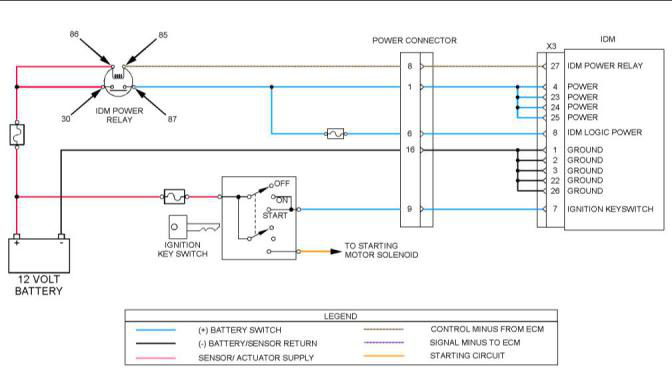
The IDM is grounded to the battery negative terminal
at IDM pins X3:1, X3:2, X3:3, X3:22 and X3:26.
The IDM receives ignition voltage at pin X3:7. The
ignition voltage signals the IDM to provide a ground
path from pin X3:27 to terminal 85 on the IDM main
power relay. Switching the relay provides power from
the battery positive terminal through a fuse and relay
terminals 30 and 87 to ECM pins X3:4, X3:23, X3:24,
and X3:25. Switching the relay also supplies power
through a fuse to pin X3:8 logic power.
Fault Detection/Management
The IDM internally monitors battery voltage. When
the IDM continuously receives less than 10.3 V or
more than 32 V, a DTC will be set.
Illustration 35
g03506173
Schematic diagram for the IDM electrical power supply
This document has been printed from SPI2. NOT FOR RESALE.
![]()
![]()
124
KENR8774
Diagnostic Functional Tests
Illustration 36
g03506844
View of the pin locations for the IDM power supply on
the IDM X3 connector
(1) Ground
(2) Ground
(3) Ground
(4) Power
(7) Ignition keyswitch
(8) IDM logic power
(22) Ground
(23) Power
(24) Power
(25) Power
(26) Ground
(27) IDM power relay
Table 55
Required Tools
Tool
Part Number
Part Description
Qty
A
27610378
Relay Breakout Harness
1
Batteries give off flammable fumes which can
explode.
To avoid injury or death, do not strike a match,
cause a spark, or smoke in the vicinity of a
battery.
This document has been printed from SPI2. NOT FOR RESALE.
![]()
![]()
![]()
![]()
![]()
KENR8774
125
Diagnostic Functional Tests
Table 56
TroubleshootingTest Steps
Values
Results
1. Inspect Electrical Connectors and Wiring
Damaged wire Result: A damaged wire or damaged connector was found. A
or connector
fuse was blown.
A. Thoroughly inspect the battery connections and the con-
nections to the keyswitch, the IDM relay and the IDM. Refer to
Troubleshooting, “Electrical Connectors - Inspect” for details.
Repair the damaged wire or the damaged connector. Replace
any blown fuses.
Use the electronic service tool to clear all logged diagnostic co-
des. Verify that the repair eliminates the fault.
B. Check the harness for abrasion and for pinch points from
the battery to the IDM, and from the keyswitch to the IDM.
Result: All connectors, pins, and sockets are correctly con-
nected and/or inserted and the harness is free of corrosion, of
abrasion or of pinch points.
C. Check the fuses.
Proceed to Test Step 2.
2. Check for Active Diagnostic Codes or Logged Diagnos- Diagnostic
Result: None of the diagnostic codes are active or recently
tic Codes
codes
logged.
A. Connect the electronic service tool to the diagnostic
connector.
If the fault is intermittent,refer to Troubleshooting, “Electrical
Connectors - Inspect”.
If the ECM is receiving no battery voltage, proceed to Test Step
3.
B. Turn the keyswitch to the ON position.
C. Check if any of the diagnostic codes listed in Table 54 are
active or recently logged.
Result: At least one of the diagnostic codes is active or re-
cently logged.
Proceed to Test Step 3.
3. Check the Batteries
Battery load test Result: The batteries do not pass the load test. The measured
passed
voltage is less than 21 V.
A. Load-test the batteries. Use a suitable battery load tester.
Refer to Systems Operation, Testing and Adjusting, “Battery -
Test” for the correct procedure.
Recharge or replace the faulty batteries.
Use the electronic service tool in order to clear all logged diag-
nostic codes and then verify that the repair eliminates the fault.
Result: The batteries pass the load test. The measured voltage
is at least 21 V.
Proceed to Test Step 4.
4. Check for Battery Voltage at the IDM Main Power Relay 21 V to 27 V
Result: The measured voltage is not within the expected
Inputs
range.
A. Turn the keyswitch to the OFF position.
If a fuse is blown, there is a short in the wiring. If a fuse is not
blown, there is an open circuit in the wiring.
B. Connect Tooling A to the IDM relay and the power distribu-
tion connector.
Repair the harness or replace the harness.
Result: The measured voltage is within the expected range.
C. Turn the keyswitch to the ON position.
Proceed to Test Step 5.
D. Use a multimeter to measure the voltage between the fol-
lowing points:
· Relay terminal 86 and ground
· Relay terminal 30 and ground
E. Turn the keyswitch to the OFF position.
(continued)
This document has been printed from SPI2. NOT FOR RESALE.

![]()
126
KENR8774
Diagnostic Functional Tests
(Table 56, contd)
TroubleshootingTest Steps
Values
Results
5. Check the IDM Relay Signal Voltage at the Relay
0.06 V to 2 V
Result: The measured voltage is within the expected range.
A. Turn the keyswitch to the ON position.
Proceed to Test Step 6.
B. Use a multimeter to measure the voltage between relay ter-
minal 85 and ground.
Result: The measured voltage is not within the expected
range.
Proceed to Test Step 7.
6. Check the Output Voltage From the Relay
21 V to 27 V
Result: The measured voltage is not within the expected
range.
A. Use a multimeter to measure the voltage between relay ter-
minal 87 and ground.
Replace the IDM power relay.
Result: The measured voltage is within the expected range.
Proceed to Test Step 7.
7. Check the Resistance of the Wiring Between the IDM
Relay and the IDM
Less than 5
Ohms
Result: At least one of the resistance measurements is greater
than 5 Ohms.
A. Turn the keyswitch to the OFF position.
B. Disconnect the X3 IDM connector.
There is an open circuit or high resistance in the wiring between
the main relay and the ECM. The fuse between relay terminal
87 and ECM X3:8 may have blown.
C. Use a multimeter to measure the resistance between the
following points:
If necessary, replace the fuse. Repair the harness or replace
the harness.
· Relay terminal 85 and IDM X3:27
· Relay terminal 87 and IDM X3:4
· Relay terminal 87 and IDM X3:23
· Relay terminal 87 and IDM X3:24
· Relay terminal 87 and IDM X3:25
· Relay terminal 87 and IDM X3:8
Result: All resistance measurements are less than 5 Ohms.
Proceed to Test Step 8.
(continued)
This document has been printed from SPI2. NOT FOR RESALE.

![]()
KENR8774
127
Diagnostic Functional Tests
(Table 56, contd)
TroubleshootingTest Steps
Values
Results
8. Check the Resistance Between the ECM Connectors
and Ground.
Less than 5
Ohms for Step is greater than 5 Ohms.
C.
Result: At least one of the resistance measurements in Step C
A. Turn the keyswitch to the OFF position.
B. Disconnect the negative battery cable.
There is an open circuit or high resistance in the wiring.
Greater than
900 Ohms for
Repair the harness or replace the harness.
Note: Use the disconnected cable for the ground test point in step D.
the following steps.
Result: At least one of the resistance measurements in Step D
is less than 900 Ohms.
C. Use a multimeter to measure the resistance between the
following points:
· IDM X3:1 and ground
There is a short to ground in the wiring.
Repair the harness or replace the harness.
· IDM X3:2 and ground
· IDM X3:3 and ground
· IDM X3:22 and ground
Result: All resistance measurements are within the expected
· IDM X3:26 and ground
range.
D. Use a multimeter to measure the resistance between the
following points:
Proceed to Test Step 10.
· IDM X3:4 and ground
· IDM X3:23 and ground
· IDM X3:24 and ground
· IDM X3:25 and ground
· IDM X3:8 and ground
· IDM X3:27 and ground
· IDM X3:7 and ground
10. Check the Resistance of the Ignition Keyswitch Signal Less than 5
Result: The measured resistance is greater than 5 Ohms.
Wire
Ohms
There is an open circuit or high resistance in the ignition key-
switch signal wire.
A. Disconnect the connector for the ignition keyswitch.
Repair the harness or replace the harness.
B. Use a multimeter to measure the resistance between the
connector for the ignition keyswitch and IDM X3:7 on the har-
ness connector.
Result: The measured resistance is less than 5 Ohms.
Replace the ignition keyswitch.
If the fault persists, contact Perkins Global Technical Support
i05538541
Note: A compressed air source of 689 kPa (100 psi)
is required in order to perform this procedure.
Injection Actuation Pressure -
Note: If the Electronic Control Module (ECM) detects
low boost pressure or an incorrect feedback signal
from the Injection Control Pressure (ICP) sensor, the
ECM commands the Injection Pressure Regulator
(IPR) valve to reduce ICP.
Test
Table 57
Required Tools
Tool
Part Number
Part Description
Qty
A
27610374
Actuator Breakout Harness
1
1
1
Pressure Sensor Breakout
Harness
B
C
27610393
27610384
ICP Sensor Adaptor
High-pressure Hose
D
E
F
3033222C
1875784C
27610398
1
1
1
ICP Sensor
UVC Sensor Breakout Harness
This document has been printed from SPI2. NOT FOR RESALE.

![]()
128
KENR8774
Diagnostic Functional Tests
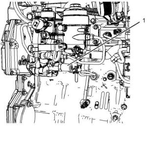
Illustration 37
g03509736
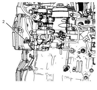
Illustration 38
g03509756
(1) IPR valve
(2) Engine Oil Temperature (EOT) sensor
1. Disconnect the engine wiring harness connector
from IPR valve (1). Inspect the engine harness
terminals and the IPR valve for corrosion, bent
pins, or pins pushed back. Make any necessary
repairs.
6. Disconnect the engine harness connector from
Engine Oil Temperature (EOT) sensor (2).
7. Slowly loosen the EOTsensor from the EOT port
until oil flows out, indicating that the oil level is
above the sensor.
2. Connect Tooling A to the IPR. Do not connect to
the engine harness.
Note: Oil will spill out, if the sensor is removed. Catch
the oil in a suitable container.
Note: If the engine harness is connected to Tooling A,
the ignition keyswitch fuse will blow or damage the
wiring harness.
If the oil level was above the EOTsensor, tighten
the sensor and reconnect the harness. Continue
with this procedure.
3. Apply battery voltage and ground to the IPR valve.
If the oil level is low, place a suitable container
under the port to catch the oil. Crank the engine
and check if oil flows out of the EOT port.
Note: Do not leave the IPR valve energized for more
than 120 seconds. This can damage the IPR valve.
If oil does not flow out while cranking, the lube oil
pump may not be supplying oil to the reservoir.
Refer to Troubleshooting, “Oil Pressure Is Low”.
If the engine starts, disconnect ground and battery
voltage from the actuator breakout harness.
4. Use the electronic service tool to monitor injection
control pressure while cranking the engine for 20
seconds. Record the results.
5. If the injection control pressure increases above
28 MPa (4061 psi), the mechanical system is
operating correctly for the engine to start. Either
the ECM is not controlling the IPR or the IPR circuit
has failed. Troubleshoot any active diagnostic
codes. Refer to Troubleshooting, “Diagnostic
Trouble Codes”. Do not continue with this
procedure until all diagnostic codes have been
cleared.
If 28 MPa (4061 psi) ICP cannot be reached,
continue with this procedure.
This document has been printed from SPI2. NOT FOR RESALE.
![]()
![]()
![]()
![]()
![]()
KENR8774
129
Diagnostic Functional Tests
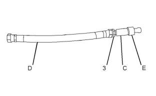
10. Install the test hose assembly to the high-
pressure pump.
Illustration 39
g03509817
Test hose
(3) 13/16-16 NPT fitting
(C) Tooling C - ICP Sensor Adaptor
(D) Tooling D - High-pressure hose
(E) Tooling E - ICP sensor
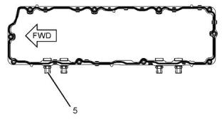
Illustration 41
g03509858
Valve cover gasket
(5) Pass-through connector for the ICP sensor
8. Fabricate a test hose assembly using Tooling C,
Tooling D, Tooling E, and a 13/16-16 NPT fitting
11. Disconnect the engine wiring harness from valve
cover gasket ICP connector (5).
Note: Retain the high-pressure hose and the ICP
sensor for future diagnostics.
12. Connect Tooling F between the high-pressure
hose assembly and the engine wiring harness.
Note: Do not connect Tooling F to the valve cover
gasket connector.
13. Connect Tooling A to the IPR. Do not connect to
the engine harness.
Note: If the engine harness is connected to Tooling A,
the ignition keyswitch fuse will blow or damage the
wiring harness.
14. Apply battery voltage and ground to the IPR
valve.
15. Use the electronic service tool to monitor the
injection control pressure while cranking the
engine for 20 seconds. Record the results.
If the ICP increases above 28 MPa (4061 psi), the
high-pressure pump and IPR are operating
correctly for the engine to start. Remove the test
hose assembly from the high-pressure pump.
Continue with this procedure.
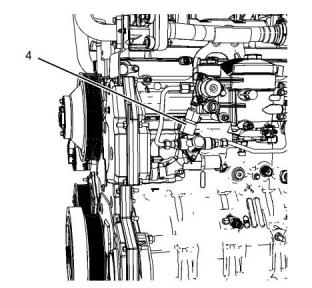
Illustration 40
g03509843
If 28 MPa (4061 psi) cannot be reached, proceed
to Test Step 26.
View of the high-pressure oil hose fitting on the high-
pressure pump (some items are not shown for
clarity).
(4) High-pressure oil hose fitting
9. Disconnect the high-pressure oil hose from high-
pressure pump fitting (4).
Note: Oil will spill from the hose. Position the high-
pressure oil hose so that oil will not spill.
This document has been printed from SPI2. NOT FOR RESALE.
![]()
![]()
![]()
![]()
![]()
![]()
![]()
130
KENR8774
Diagnostic Functional Tests
Perform any necessary repairs.
25. Install the valve mechanism cover. Refer to
Disassembly and Assembly, “Valve Mechanism
Cover - Remove and Install”.
26. Remove Tooling C and Tooling E from Tooling D.
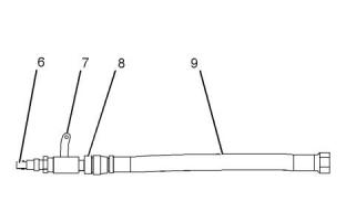
Illustration 42
g03509859
(6) Air line fitting
(7) In-line shut-off valve
(8) 13/16-16 NPT fitting
(9) High-pressure oil hose
16. Install a 13/16-16 NPT fitting, a shut-off valve, and
an air line fitting to the high-pressure oil hose that
is connected to the cylinder head.
Illustration 43
g03509859
Note: If the system does not leak when air pressure
is applied, the system will maintain pressure. When
the hose is removed, oil will be released with air
pressure. Use the in-line shut-off valve to control and
contain bleed-off mixture (air and oil).
27. Install a 13/16-16 NPT fitting, a shut-off valve, and
an air line fitting to the high-pressure oil hose that
is connected to the cylinder head.
28. Remove the oil level gauge from the oil fill tube.
17. Remove the oil level gauge from the oil fill tube.
29. Close the in-line shut-off valve.
18. Close the in-line shut-off valve.
30. Connect the air supply to the air line fitting.
19. Connect the air supply to the air line fitting.
31. Apply 689 kPa (100 psi) of pressure. Slowly open
the shut-off valve.
20. Apply 689 kPa (100 psi) of pressure. Slowly open
the shut-off valve.
32. Listen for an air leak in the crankcase through the
oil fill tube.
21. Listen for an air leak in the crankcase through the
oil fill tube.
A leak should be heard through the IPR valve
when the IPR valve is not energized.
If a leak is not heard, go back and check previous
test results.
33. Connect Tooling A to the IPR. Do not connect to
the engine harness.
If a leak is heard, continue with this procedure.
Note: If the engine harness is connected to Tooling A,
the ignition keyswitch fuse will blow or damage the
wiring harness.
22. Close the in-line shut-off valve to stop the air flow.
23. Remove the valve mechanism cover. Refer to
Disassembly and Assembly, “Valve Mechanism
Cover - Remove and Install”.
34. Apply battery voltage and ground to the IPR
valve. Listen for an air leak in the crankcase
through the oil fill tube.
24. Open the in-line shut-off valve and listen for leaks.
Check the following components:
If the IPR valve is energized, the air leak should
stop.
• Injector oil inlet adaptor and o-rings
• ICP sensor
Note: Do not leave the IPR valve energized for more
than 120 seconds. This can damage the IPR valve.
• O-ring for the high-pressure oil rail
• End plugs in the high-pressure oil rail
If the air leak does not stop, replace the IPR valve.
Refer to Disassembly and Assembly, “Injection
Actuation Pressure Control Valve - Remove and
Install”.
This document has been printed from SPI2. NOT FOR RESALE.
![]()

![]()
![]()
![]()
![]()
KENR8774
131
Diagnostic Functional Tests
If the air leak stops, continue with this procedure.
35. Remove the high-pressure oil pump. Refer to
Disassembly and Assembly, “Unit Injector
Hydraulic Pump - Remove and Install”.
Check that the high-pressure oil pump gear is
tightened to a torque of 224 N·m (165.21344 lb ft).
If the high-pressure oil pump gear is tight, or the
pump cam does not rotate, replace the pump.
Refer to Disassembly and Assembly, “Unit Injector
Hydraulic Pump - Remove and Install”.
If this procedure did not rectify the fault, contact
Perkins Global Technical Support.
i05543549
Injection Actuation Pressure
Control Valve - Test
This procedure covers the following codes:
Table 58
Diagnostic Trouble Codes
DTC
Code Description
Comments
Injection Control Pressure regulator DTC 241 is set b, y the Electronic Control Module (ECM) when the Output Circuit Check
OCC self test failed
(OCC) test has failed after the Key-On Engine-Off (KOEO) Standard Test has been run.
241
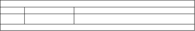
Follow the troubleshooting procedure in order to identify the root cause of the fault.
The IPR valve is supplied with voltage at pin A of the
IPR connector through a 12-pin connector (pin 9)
from the ignition keyswitch. The control of the
injection control system is gained by the ECM
grounding pin B of the IPR valve through pin X1:12 of
the ECM. Precise control is gained by varying the
percentage of ON/OFF time of the IPR solenoid. A
high duty cycle indicates a high amount of injection
control pressure is being commanded. A low duty
cycle indicates less pressure being commanded.
Fault Detection/Management
An open or short to ground in the Injection Control
Pressure (ICP) circuit can be detected by an on-
demand output circuit check during KOEO Standard
Test. If there is a circuit fault detected, a Diagnostic
Trouble Code (DTC) will be set. When the engine is
running, the ECM can detect if the ICP is equal to the
desired pressure. When the measured ICP does not
compare to the desired pressure, the ECM will ignore
the measured ICP signal and controls the engine with
the desired value.
This document has been printed from SPI2. NOT FOR RESALE.
![]()
132
KENR8774
Diagnostic Functional Tests
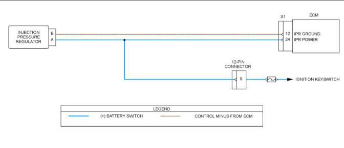
Illustration 44
g03510058
Illustration 45
g03510138
View of the pin locations for the IPR valve on the X1
ECM connector
(12) IPR ground
(24) IPR power
Table 59
Required Tools
Tool
Part Number
Part Description
Qty
A
27610374
Actuator Breakout Harness
1
This document has been printed from SPI2. NOT FOR RESALE.
![]()
![]()
![]()
![]()
KENR8774
133
Diagnostic Functional Tests
Table 60
TroubleshootingTest Steps
Values
Results
1. Inspect Electrical Connectors and Wiring
Damaged wire Result: A damaged wire or damaged connector was found.
or connector
A. Thoroughly inspect the connections to the IPR, the ECM X1
connector, the 12-pin connector, and the ignition keyswitch.
Refer to Troubleshooting, “Electrical Connectors - Inspect” for
details.
Repair the damaged wire or the damaged connector.
Use the electronic service tool to clear all logged diagnostic co-
des. Verify that the repair eliminates the fault.
Result: All connectors, pins, and sockets are correctly con-
nected and/or inserted and the harness is free of corrosion, of
abrasion or of pinch points.
B. Check the harness for abrasion and for pinch points from
the IPR to the ECM, and from the keyswitch to the IPR.
Proceed to Test Step 2.
2. Run the Key-On Engine-Off (KOEO) Standard Test
Diagnostic
codes
Result: A 241 diagnostic code is not active.
A. Connect the electronic service tool to the diagnostic
connector.
The IPR valve circuit appears to be operating correctly at this
time.
If a fault is still suspected, proceed to Test Step 3 in order to
continue testing the IPR valve circuit.
B. Turn the keyswitch to the ON position.
C. Select “Tests” from the menu bar. Select “Key-On Engine-
Off” from the drop-down menu.
Result: A 241 diagnostic code is active.
D. From the KOEO Diagnostics menu, select “Standard” ,
then select “Run” .
Proceed to Test Step 3.
Note: This test takes less than 5 seconds.
E. Record all active diagnostic codes.
3. Check the Voltage at IPR Valve Connector
21 V to 27 V for Result: The voltage measurement between IPR valve pin A
Step E. and ground is not within the expected range.
A. Turn the keyswitch to the OFF position.
Less than 0.25 There is an open circuit in the wiring between the fuse for the
V for step F. ignition keyswitch and the IPR valve connector.
Repair the harness or replace the harness.
B. Disconnect the engine harness connector from the IPR
valve.
C. Connect Tooling A to the harness connector for the IPR
valve.
Result: The voltage measurement between IPR valve pin B
and ground is greater than 0.25 V.
D. Turn the keyswitch to the ON position.
The IPR valve ground wire is shorted to another voltage
source.
E. Use a multimeter to measure the voltage between IPR
valve pin A and ground.
Repair the harness or replace the harness.
F. Use a multimeter to measure the voltage between IPR valve
pin B and ground.
Result: The voltage measurements are within the expected
range.
Proceed to Test Step 4.
(continued)
This document has been printed from SPI2. NOT FOR RESALE.

![]()
134
KENR8774
Diagnostic Functional Tests
(Table 60, contd)
TroubleshootingTest Steps
Values
Results
4. Check the Resistance Between the 12-Pin Connector
and the IPR Valve Connector
Less than 5
Ohms
Result: The measured resistance is greater than 5 Ohms.
There is an open circuit in the wiring between the 12-pin con-
nector and the IPR valve connector.
A. Turn the keyswitch to the OFF position.
B. Disconnect the 12-pin connector.
Repair the harness or replace the harness.
Result: The measured resistance is less than 5 Ohms.
Proceed to Test Step 5.
C. Remove the fuse from the ignition keyswitch circuit.
D. Use a multimeter to measure the resistance between pin 9
on the 12-pin connector and pin A on the harness connector
for the IPR valve.
5. Check the Resistance of the IPR Circuit Including the
IPR Valve
5 Ohms to 20 Result: The resistance measurement is within the expected
Ohms
range.
A. Turn the keyswitch to the OFF position.
The IPR valve circuit appears to be OK.
If a fault persists, contact Perkins Global Technical Support.
B. Disconnect the ECM X1 connector.
Result: The resistance measurement is not within the expected
C. Disconnect Tooling A from the engine harness.
D. Connect the engine harness connector to the IPR valve.
E. Remove the fuse from the ignition keyswitch circuit.
range.
Proceed to Test Step 6.
F. Use a multimeterto measure the resistance between ECM
X1:12 and the fuse connector.
6. Check the Resistance of the IPR Valve Coil
5 Ohms to 20 Result: The resistance measurement is not within the expected
Ohms
range.
A. Disconnect the engine harness connector from the IPR
valve.
Replace the IPR valve. Refer to Disassembly and Assembly,
“Injection Actuation Pressure Control Valve - Remove and
Install”.
B. Connect Tooling A to the IPR valve.
C. Use a multimeter to measure the resistance between pin A
and pin B on the IPR valve.
Result: The resistance measurement is within the expected
range.
The fault is in the wiring or the connectors. Refer to Trouble-
shooting, “Electrical Connector - Inspect” in order to identify the
fault.
i05546457
Injection Actuation Pressure
Sensor - Test
This procedure covers the following codes:
This document has been printed from SPI2. NOT FOR RESALE.

![]()
KENR8774
135
Diagnostic Functional Tests
Table 61
Diagnostic Trouble Codes
DTC
Code Description
Comments
DTC 124 is set by the Electronic Control Module (ECM) if signal voltage is less than
0.039 V for more than 1 second.
Injection Control Pressure signal
out-of-rangelow
124
125
332
DTC 124 can be set due to an open circuit or short to ground on the signal circuit, a failed
Injection Control Pressure (ICP) sensor. The DTC can also be set due to the sensor sup-
ply circuit being open or shorted to ground.
DTC 125 is set by the ECM if the signal voltage is greater than 4.9 V for more than 0.1
second.
Injection Control Pressure signal
out-of-rangehigh
DTC can be set due to the signal circuit shorted to the sensor supply voltage or battery
voltage.
DTC 332 is set by the ECM if the voltage signal from the ICP sensor is greater than ex-
pected with the keyswitch in the ON position and the engine not running.
Injection Control Pressure above
spec. with engine not running
If the ECM sets DTC 332, the ECM will ignore the ICP signal and operate the IPR with
fixed values based on engine operating conditions.
Follow the troubleshooting procedure in order to identify the root cause of the fault.
Function
The ECM continuously monitors the signal of the ICP
sensor to determine if the signal is within an expected
range. If the ECM detects a voltage greater or less
than expected, the ECM will set a DTC, ignore the
ICP sensor signal, and use a preset value based on
engine operating conditions.
The ICP sensor is a micro strain gauge sensor. The
ICP sensor is under the valve cover, forward of the
No. 6 fuel injector in the high-pressure oil rail. The
engine harness connection on the valve cover gasket
for the ICP sensor is left of the No. 1 and No. 2
injector connector. The ECM supplies a 5 V reference
signal which the ICP sensor uses to produce a linear
analog voltage that indicates pressure.
The ICP sensor provides a feedback signal voltage to
the ECM indicating injection control pressure. The
ECM monitors ICP as the engine is operating to
modulate the IPR. This is a closed loop function
which means the ECM continuously monitors and
adjusts for ideal ICP determined by conditions such
as load, speed, and temperature.
The ECM monitors the ICP signal to determine if the
performance of the hydraulic system is satisfactory.
During engine operation, if the ECM recognizes that
the ICP signal is greater or less than the value that
the Injection Pressure Regulator is trying to achieve,
the ECM will set a DTC.
The ICP signal from the ECM is one of the signals the
Injector Driver Module uses to command the correct
injector timing.
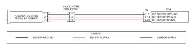
ICP Circuit Operation
The ICP sensor is supplied a 5 V reference signal at
Pin 2 through valve cover gasket pin 8 from ECM pin
X1:14. The ICP sensor supplied a signal ground at
pin 1 through valve cover gasket pin 7 from ECM pin
X1:6. The ECM monitors the ICP signal from sensor
pin 3 through valve cover gasket pin 6 to ECM pin
X1:20.
Fault Detection/Management
This document has been printed from SPI2. NOT FOR RESALE.

![]()
136
KENR8774
Diagnostic Functional Tests
Illustration 46
g03514918
Schematic diagram of the ICP sensor circuit
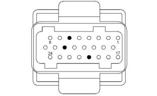
Illustration 47
g03520740
View of the pin locations for the ICP sensor on the X1
ECM connector
(6) Ground
(14) Power
(20) Signal
Table 62
Required Tools
Tool
A
Part Number
27610376
27610375
Part Description
4mm Plug 3-way Harness
500 Ohm Resistor Harness
Qty
1
1
B
Under Valve Cover Sensor
Breakout Harness
C
27610398
1
This document has been printed from SPI2. NOT FOR RESALE.
![]()
![]()
![]()
![]()
KENR8774
137
Diagnostic Functional Tests
Table 63
TroubleshootingTest Steps
Values
Results
1. Inspect Electrical Connectors and Wiring
Damaged wire Result: A damaged wire or damaged connector was found.
or connector
A. Thoroughly inspect the connections to the ICP sensor, the
ECM X1 connector, and the valve cover connector. Refer to
Troubleshooting, “Electrical Connectors - Inspect” for details.
Repair the damaged wire or the damaged connector.
Use the electronic service tool to clear all logged diagnostic co-
des. Verify that the repair eliminates the fault.
B. Check the harness for abrasion and for pinch points from
the ICP sensor to the ECM.
Result: All connectors, pins, and sockets are correctly con-
nected and/or inserted and the harness is free of corrosion, of
abrasion or of pinch points.
Proceed to Test Step 2.
2. Run the Key-On Engine-Off(KOEO) Continuous Monitor
Test
Diagnostic
codes
Result: One of the Diagnostic codes listed in Table 61 is
active.
A. Connect the electronic service tool to the diagnostic
connector.
Proceed to Test Step 3.
B. Turn the keyswitch to the ON position.
Result: One of the Diagnostic codes listed in Table 61 became
active only when wiggling the connectors.
C. Select “Tests” from the menu bar. Select “Key-On Engine-
Off” from the drop-down menu.
Repair or replace any suspect connectors.
D. From the KOEO Diagnostics menu, select “Continuous
Monitor” , then select “Run” .
E. Monitor the ICP signal voltage and verify any active DTCs
for the ICP sensor circuit.
F. Wiggle the connectors associated with the ICP sensor
circuit.
3. Check the Signal Voltage With the Sensor
Disconnected
Less than 0.039 Result: The voltage measurement is greater than 0.039 V.
V
There is a short to another voltage source on the sensor signal
A. Turn the keyswitch to the OFF position.
wire.
Repair the harness or replace the harness.
B. Remove the valve cover. Refer to Disassembly and Assem-
bly, “Valve Mechanism Cover - Remove and Install”. Leave the
valve cover harness connected to the engine harness.
Result: The voltage measurement is less than 0.039 V
Proceed to Test Step 4.
C. Disconnect the ICP sensor from the valve cover harness
connector.
D. Turn the keyswitch to the ON position.
E. Use the electronic service tool to monitor the ICP sensor
signal voltage.
(continued)
This document has been printed from SPI2. NOT FOR RESALE.

![]()
138
KENR8774
Diagnostic Functional Tests
(Table 63, contd)
TroubleshootingTest Steps
Values
Results
4. Check the Sensor Supply Voltage
4.5 V to 5.5 V Result: The measured voltage is greater than 5.5 V.
There is a short to battery in the sensor power wiring.
Repair the harness or replace the harness.
A. Turn the keyswitch to the OFF position.
B. Connect Tooling C to ICP connector on the valve cover
harness.
Result: The measured voltage is less than 4.5 V
C. Turn the keyswitch to the ON position.
There is an open circuit or short to ground in the sensor power
wiring.
D. Use a multimeter to measure the voltage between pin 2 on
the breakout harness and ground.
Result: The measured voltage is within the expected range.
Proceed to Test Step 5.
5. Monitor the Signal Voltage With the 500 Ohm Resistor
Harness Installed
4.9 V to 5.1 V Result: The measured voltage is less than 4.9 V.
Proceed to Test Step 6.
A. Turn the keyswitch to the OFF position.
B. Install Tooling B between pin 2 and pin 3 on Tooling C.
C. Turn the keyswitch to the ON position.
Result: The measured voltage is within the expected range.
Proceed to Test Step 8.
D. Use the electronic service tool to monitor the ICP sensor
signal voltage.
E. Turn the keyswitch to the OFF position.
F. Remove Tooling B.
6. Check for a Short to Ground in the Sensor Signal Wire Greater than 1 k Result: The measured resistance is less than 1 k Ohm.
Ohm
A. Turn the keyswitch to the OFF position.
B. Disconnect the negative battery cable.
There is a short to ground in the sensor signal wiring.
Repair the harness or replace the harness.
Result: The measured resistance is greater than 1 k Ohm.
C. Use a multimeter to measure the resistance between pin 3
on Tooling C and the disconnected negative battery cable.
Proceed to Test Step 7.
7. Check the Sensor Signal Wire for an Open Circuit
A. Turn the keyswitch to the OFF position.
Less than 5
Ohms
Result: The measured resistance is greater than 5 Ohms.
There is an open circuit or high resistance in the sensor signal
wire.
B. Disconnect the engine harness connector from ECM X1.
Repair the harness or replace the harness.
C. Use a multimeter to measure the resistance between pin 3
on Tooling C and terminal X1:20 on the engine harness
connector.
Result: The measured resistance is less than 5 Ohms.
Proceed to Test Step 8.
(continued)
This document has been printed from SPI2. NOT FOR RESALE.

![]()
KENR8774
139
Diagnostic Functional Tests
(Table 63, contd)
TroubleshootingTest Steps
Values
Results
8. Check the Resistance of the Sensor Ground Wire
A. Turn the keyswitch to the OFF position.
Less than 5
Ohms
Result: The measured resistance is greater than 5 Ohms.
There is an open circuit or high resistance in the sensor ground
wiring.
B. Disconnect the engine harness connector from ECM X1.
Repair the harness or replace the harness.
C. Use a multimeter to measure the resistance between pin 1
on Tooling C and terminal X1:6 on the engine harness
connector.
Result: The measured resistance is less than 5 Ohms.
Remove all tooling, reconnect all disconnected connectors, and
install all removed components. Use the electronic service tool
to clear all active diagnostic codes.
Proceed to Test Step 9.
9. Check for Active Diagnostic Codes
Diagnostic
codes
Result: One of the diagnostic codes listed in Table 61 is still
active.
A. Turn the keyswitch to the ON position.
Replace the ICP sensor. Refer to Disassembly and Assembly,
“Injection Actuation Pressure Control Sensor - Remove and
Install”.
B. Use the electronic service tool to run the “KOEO Standard
Test” .
If the fault persists, contact Perkins Global Technical Support.
C. Use the electronic service tool to check for active diagnos-
tic codes.
Result: The diagnostic code is no longer active.
Return the engine to service.
i05561312
Injector Solenoid - Test
This procedure covers the following codes:
Table 64
Diagnostic Trouble Codes
DTC
Code Description
Comments
High side to low side open (cylinder
1)
421
High side to low side open (cylinder
2)
422
423
424
425
426
431
432
High side to low side open (cylinder
3)
DTCs 421-426 are set by the Electronic Control Module (ECM) when the rising time is too
High side to low side open (cylinder long for the open or close coil. These codes normally indicate a harness or a coil is open.
4)
High side to low side open (cylinder
5)
High side to low side open (cylinder
6)
High side shorted to low side (cylin-
der 1)
DTCs 431-436 are set by the ECM when the rising time to 20 A is short, but not zero for
High side shorted to low side (cylin- the open or close coil. These codes normally indicate an internally shorted coil.
der 2)
(continued)
This document has been printed from SPI2. NOT FOR RESALE.

![]()
140
KENR8774
Diagnostic Functional Tests
(Table 64, contd)
Diagnostic Trouble Codes
DTC
Code Description
Comments
High side shorted to low side (cylin-
der 3)
433
High side shorted to low side (cylin-
der 4)
434
435
436
451
452
453
454
455
456
High side shorted to low side (cylin-
der 5)
High side shorted to low side (cylin-
der 6)
High side short to ground or VBAT
(cylinder 1)
High side short to ground or VBAT
(cylinder 2)
High side short to ground or VBAT
(cylinder 3)
DTCs 451-456 are set by the ECM when the rising time to 20 A is zero for the open or
close coil. These codes normally indicate the harness or coil is shorted to ground.
High side short to ground or VBAT
(cylinder 4)
High side short to ground or VBAT
(cylinder 5)
High side short to ground or VBAT
(cylinder 6)
Follow the troubleshooting procedure in order to identify the root cause of the fault.
Function
When the engine is running, the IDM can detect
individual injector coil open and shorts to ground or
battery. A Key-On Engine-Off (KOEO) Injector Test
allows the operator to enable all injector coils when
the engine is off to verify circuit operation. When the
IDM detects a fault, DTCs are transmitted over the
CAN datalink between the ECM and the IDM.
The Injector Driver Module (IDM) is used to control
the injectors. The IDM receives camshaft position and
crankshaft position signals and fueling information via
the CAN datalink from the ECM. The IDM calculates
injection timing and injector actuation time based on
the fuel quantity requested for any engine operating
condition.
The IDM transmits a high and low side drive output to
the injectors. The high side output supplies the
injectors with a power supply of 48 VDC at 20 A. The
low side output supplies a return circuit to each
injector coil.
Injector Circuit Operation
When a coil needs to be energized, the IDM turns on
both the high side and low side driver.
The injectors are under the valve cover. Each injector
has a close and open coil. The IDM continuously
monitors the amount of time (rising time) taken by
each coil to draw 20 A. The time is compared to
calibrated values and the IDM determines if a circuit
or injector fault exists. Each injector has six failure
modes and 3 DTCs. A failure can occur on the open
or close coil circuit.
High Side Drive Output
The IDM regulates the current at an average of 20 A.
When the current reaches 24 A, the IDM shuts off the
high side driver. When the current drops to 16 A, the
IDM turns on the high side driver.
Low Side Drive Return
When a short to ground condition is detected on an
injector (low or high side), The IDM discontinues
power to the shorted injector and operates the engine
on the remaining cylinders.
The injector solenoids are grounded through the low
side return circuits. The ECM monitors the low side
return circuits. The ECM monitors the low side return
signal for diagnostic purposes and utilizes the fly
back current from the injector solenoids to help
charge the drive capacitors internal to the ECM.
The last digit of the injector DTC corresponds to the
cylinder where the fault has been detected.
Fault Detection/Management
This document has been printed from SPI2. NOT FOR RESALE.