 English
 Espaol
 Franais
 阿拉伯
阿拉伯 中文
中文 Deutsch
 Italiano
 Português
 日本
日本 韩国
韩国 български
 hrvatski
 esky
esky Dansk
Dansk Nederlands
 suomi
suomi Ελληνικ
 印度
印度 norsk
norsk Polski
 Roman
Roman русский
 Svenska
珀金斯Perkins1506A-E88TA、1506C-E88TA、1506D-E88TA发动机维修技术资料供应商,珀金斯Perkins1506A-E88TA、1506C-E88TA、1506D-E88TA发动机维修技术资料技术价格规格咨询服务,珀金斯Perkins1506A-E88TA、1506C-E88TA、1506D-E88TA发动机维修技术资料零配件供应,珀金斯Perkins1506A-E88TA、1506C-E88TA、1506D-E88TA发动机维修技术资料售后服务中心,珀金斯Perkins1506A-E88TA、1506C-E88TA、1506D-E88TA发动机维修技术资料,珀金斯Perkins1506A-E88TA、1506C-E88TA、1506D-E88TA发动机维修技术资料详细的技术参数,

产品中心
珀金斯Perkins1506A-E88TA、1506C-E88TA、1506D-E88TA发动机维修技术资料
详细描述
Specifications
1506A-E88TA, 1506C-E88TA and 1506D-
E88TA Industrial Engines
LG
(Engine)
PK9 (Engine)
This document has been printed from SPI2. NOT FOR RESALE
![]()
![]()
![]()
![]()

Important Safety Information
Most accidents tha t involve produc t op eration, ma intena nc e and repair are caus ed by failure to
ob serve basic safety rules or precautions . An accident can often be avoided by recog nizing pote ntially
ha za rdous situations before an accident oc curs . A person mus t be alert to pote ntial ha za rds. This
person should also ha ve the ne cessary training, skills and tools to perform the se func tions properly.
Improper operation, lubrication, maintenance or repair of this product can be dangerous and
could result in injury or death.
Do not operate or perform any lubrication, maintenance or repair on this product, until you have
read and understood the operation, lubrication, maintenance and repair information.
Sa fety precautions and warning s are provided in this ma nua l and on the produc t. If the se ha za rd
warning s are not he eded, bod ily injury or death could oc cur to you or to othe r persons .
The ha za rds are identified by the “Safety Alert Symb ol” and followed by a “Signa l Word” suc h as
“DANGER”, “WARNING” or “CAUTION”. The Sa fety Alert “WARNING” label is shown below.
The me aning of this safety alert symb ol is as follows:
Attention! Become Alert! Your Safety is Involved.
The me ssage tha t appears und er the warning explains the ha za rd and can be either written or
pictorially presente d.
Op erations tha t ma y caus e produc t dama ge are identified by “NOTICE” labels on the produc t and in
this pub lication.
Perkins cannot anticipate every possible circumstance that might involve a potential hazard. The
warnings in this publication and on the product are, therefore, not all inclusive. If a tool, procedure,
work method or operating technique that is not specifically recommended by Perkins is used,
you must satisfy yourself that it is safe for you and for others. You should also ensure that the
product will not be damaged or be made unsafe by the operation, lubrication, maintenance or
repair procedures that you choose.
The informa tion, specifications , and illustrations in this pub lication are on the basis of informa tion tha t
was available at the time tha t the pub lication was written. The specifications , torque s, pressure s,
me asure me nts , adjustme nts , illustrations , and othe r items can cha ng e at any time. These cha ng es can
affect the service tha t is given to the produc t. Ob tain the comp lete and mos t current informa tion before
you start any job. Pe rkins dealers or Pe rkins distributors ha ve the mos t current informa tion available.
When replacement parts are required for this
product Perkins recommends using Perkins
replacement parts.
Failure to heed this warning can lead to prema-
ture failures, product damage, personal injury or
death.
This document has been printed from SPI2. NOT FOR RESALE
![]()
![]()
UENR4509
3
Table of Contents
Table of Contents
Electric Starting Motor .................. .................. 40
Electric Starting Motor (Model PK9) ....... ....... 40
Coolant Temperature Sensor............. ............. 41
Fuel Temperature Sensor................ ............... 41
Fuel Pressure Sensor................... .................. 41
Injection Actuation Pressure Sensor ....... ....... 42
Engine Oil Pressure Sensor.............. ............. 42
Atmospheric Pressure Sensor............ ............ 43
Inlet Air Temperature Sensor............. ............. 43
Speed/Timing Sensor................... .................. 44
Electronic Control Module ............... ............... 44
SpecificationsSection
Engine Design ......................... ......................... 4
Fuel Filter Base (Primary Fuel Filter Base)... ... 4
Fuel Filter Base (Secondary Fuel Filter Base). 5
Fuel Filter Base (Secondary Fuel Filter Base,
Model PK9)........................... .......................... 5
Unit Injector Hydraulic Pump.............. .............. 6
Unit Injector............................ ........................... 6
Lifter Group............................ ........................... 8
Valve Mechanism ....................... ...................... 8
Valve Mechanism Cover.................. ................. 9
Cylinder Head Valves ................... .................. 10
Cylinder Head......................... ........................ 13
Turbocharger......................... ......................... 15
Turbocharger (Model PK9)............... .............. 16
Air Inlet Elbow......................... ........................ 17
Exhaust Manifold...................... ...................... 18
Camshaft............................ ............................ 18
Engine Oil Filter Base................... .................. 19
Engine Oil Pan........................ ........................ 20
Crankcase Breather.................... .................... 21
Water Temperature Regulator Housing..... ..... 21
Water Temperature Regulator Housing..... ..... 22
Water Temperature Regulator ............ ............ 22
Water Pump.......................... .......................... 24
Water Pump (Model PK9)............... ............... 26
Cylinder Block Cover Group.............. ............. 27
Cylinder Block......................... ........................ 27
Cylinder Liner......................... ......................... 29
Crankshaft........................... ........................... 30
Crankshaft Seals ...................... ...................... 30
Vibration Damper and Pulley............. ............. 31
Connecting Rod Bearing Journal.......... .......... 31
Main Bearing Journal................... ................... 31
Connecting Rod....................... ....................... 32
Piston and Rings ...................... ...................... 33
Piston Cooling Jet...................... ..................... 34
Front Housing and Covers............... ............... 34
Gear Group (Front)..................... .................... 35
Flywheel .......................................................... 36
Flywheel Housing...................... ..................... 36
Belt Tension Chart ..................... ..................... 36
Belt Tensioner (Model PK9).............. .............. 37
Refrigerant Compressor (Model PK9) ...... ...... 38
Fan Drive............................ ............................ 38
Alternator and Regulator................. ................ 38
Alternator and Regulator (Model PK9)...... ..... 39
Index Section
Index................................ ............................... 45
This document has been printed from SPI2. NOT FOR RESALE
![]()
4
UENR4509
Specifications Section
SpecificationsSection
i06004069
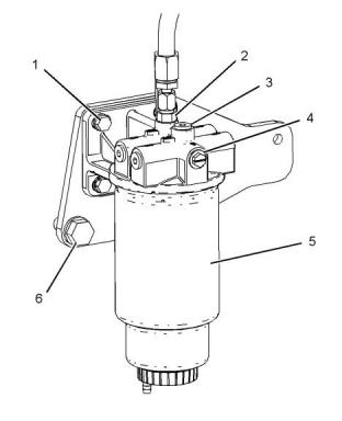
Fuel Filter Base
(Primary Fuel Filter Base)
i02841820
Engine Design
If necessary, install a new fuel primary fuel filter (5).
Refer to Operation and Maintenance Manual, “Fuel
System Primary Filter (Water Separator) Element -
Replace” for the correct procedure.
Illustration 1
g01101255
Cylinder and valve location
(A) Exhaust valves
(B) Inlet valves
Bore ............................................112.0 mm (4.41 inch)
Stroke ........................................149.0 mm (5.87 inch)
Displacement.....................................8.8 L (537 cu in)
Cylinder arrangement .....................In-line six cylinder
Valves per cylinder .................................................... 4
Type of combustion ..............................Direct injection
Valve lash with engine stopped (cold)
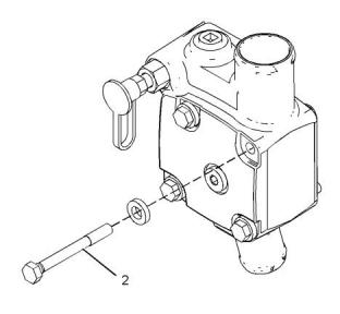
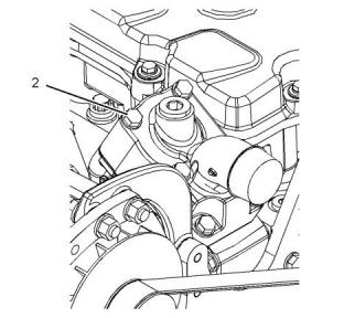
Illustration 2
g03767316
Typical example
(1) Tighten the bolts to the following torque......55 N·m
(41 lb ft)
Inlet..............0.38 ± 0.08 mm (0.015 ± 0.003 inch)
Exhaust.......0.64 ± 0.08 mm (0.025 ± 0.003 inch)
(2) Tighten the adaptor to the following torque.
............................................................30 N·m (22 lb ft)
Note: The front of the engine is opposite of the
flywheel end of the engine. The left side and the right
side of the engine are viewed from the flywheel end of
the engine. The no. 1 cylinder is the front cylinder.
(3) Tighten the plugs to the following torque.
.........................................................22 N·m (195 lb in)
(4) Tighten the plug to the following torque. .....30 N·m
(22 lb ft)
Crankshaft rotation direction (view from the flywheel
end) .................................................Counterclockwise
(6) Tighten the bolts to the following torque.
Firing order (injection sequence) ...........1, 5, 3, 6, 2, 4
..........................................................100 N·m (74 lb ft)
This document has been printed from SPI2. NOT FOR RESALE
![]()

![]()
![]()
![]()
![]()
UENR4509
5
Specifications Section
i06004049
(7) Tighten the bolt to the following torque. ......12 N·m
(106 lb in)
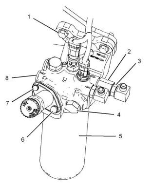
Fuel Filter Base
(Secondary Fuel Filter Base)
(8) Tighten the plugs to the following torque.
............................................................40 N·m (30 lb ft)
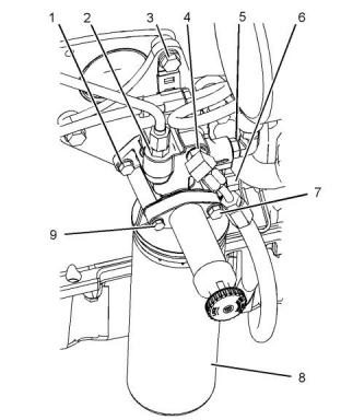
i06228953
Fuel Filter Base
(Secondary Fuel Filter Base,
Model PK9)
If necessary, install a new secondary fuel filter (5).
Refer to Operation and Maintenance Manual, “Fuel
System Secondary Filter - Replace” for the correct
procedure.
If necessary, install a new secondary fuel filter (8).
Refer to Operation and Maintenance Manual, “Fuel
System Secondary Filter - Replace” for the correct
procedure.
Illustration 3
g03767376
Typical example
(1) Tighten the bolts to the following torque......55 N·m
(41 lb ft)
Illustration 4
g03863013
(2) Tighten the connector to the following torque.
Typical example
............................................................50 N·m (37 lb ft)
(1) Tighten the bolts to the following torque......28 N·m
(21 lb ft)
(3) Tighten the elbows to the following torque.
............................................................50 N·m (37 lb ft)
(2) Tighten the adaptor to the following torque.
............................................................40 N·m (30 lb ft)
(4) Tighten the valves to the following torque.
............................................................65 N·m (48 lb ft)
(3) Tighten the bolts to the following torque......55 N·m
(41 lb ft)
(6) Tighten the bolt to the following torque. ......28 N·m
(21 lb ft)
This document has been printed from SPI2. NOT FOR RESALE
![]()
![]()
![]()
![]()
![]()
6
UENR4509
Specifications Section
(4) Tighten the elbow to the following torque.
............................................................40 N·m (30 lb ft)
Use the following procedure in order to torque the
cover bolts.
1. Torque the bolts to 8 N·m (70 lb in).
(5) Tighten the elbow to the following torque.
............................................................40 N·m (30 lb ft)
2. Turn the bolts for an additional 24 degrees.
(6) Tighten the nipple to the following torque.
............................................................30 N·m (22 lb ft)
3. Ensure that the torque of the bolts is 10.2 N·m
(90 lb in).
(7) Tighten the bolt to the following torque. ......28 N·m
(21 lb ft)
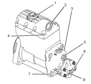
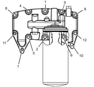
(5) Oil outlet port
Torque for mating fitting................48 N·m (35 lb ft)
(6) Fuel outlet port
(9) Tighten the bolt to the following torque. ......12 N·m
(106 lb in)
Torque for mating fitting................23 N·m (17 lb ft)
(7) Tie bolts for pump housing
i05982963
Unit Injector Hydraulic Pump
Use the following procedure in order to tighten the tie
bolts for the pump housing.
1. Torque the bolts to 17 N·m (13 lb ft).
2. Turn the bolts for an additional 35 degrees.
3. Ensure that the torque of the bolts is 33 N·m
(24 lb ft).
(8) Fuel inlet port
Torque for mating fitting................23 N·m (17 lb ft)
Pump performance.
Rated pump speed ..............................3312 RPM
Maximum intermittent speed of the pump .... 5000
RPM
Maximum continuous operating pressure
.................................................28 MPa (4050 psi)
Relief valve opening pressure ..................31 MPa
(4500 psi)
Nut for the pump gear (not shown)
Use the following procedure to tighten the nut for the
pump gear.
1. Torque the nut to 50 N·m (37 lb ft).
2. Turn the nut for an additional 35.5 degrees.
Illustration 5
g01101301
i02820444
Typical example
Unit Injector
(1) Unit injector hydraulic pump
(2) Oil inlet port
Torque for mating fitting................40 N·m (30 lb ft)
(3) Fuel transfer pump
(4) Cover bolts
This document has been printed from SPI2. NOT FOR RESALE
![]()
![]()
![]()
UENR4509
7
Specifications Section
Note: Lubricate the bore in the cylinder head lightly
with the lubricant that is being sealed.
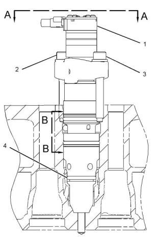
Note: Install the fuel injector group (1) so the
electrical connector is facing toward the exhaust side
of the cylinder head.
Use the following procedure to install the fuel injector
group:
1. Seat the fuel injector group in the bore.
2. Tighten the bolt (2) which is closest to the exhaust
side (5) of the cylinder head until the bolt is seated.
3. Tighten the bolt (3) which is closest to the inlet side
(6) of the cylinder head to 12 ± 1 N·m
(105 ± 9 lb in).
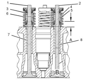
Illustration 6
g01407502
(4) O-ring seal
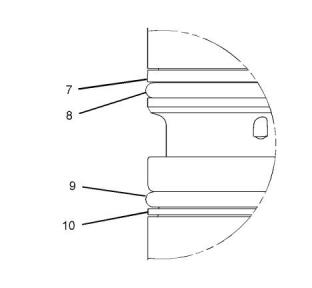
Illustration 8
g01407507
View B-B
(7) Backup ring
(8) O-ring seal
(9) O-ring seal
(10) Backup ring
Illustration 7
g01407503
View A-A
This document has been printed from SPI2. NOT FOR RESALE
![]()
![]()
![]()
![]()
![]()
![]()
![]()
8
UENR4509
Specifications Section
i05966860
Valve Mechanism
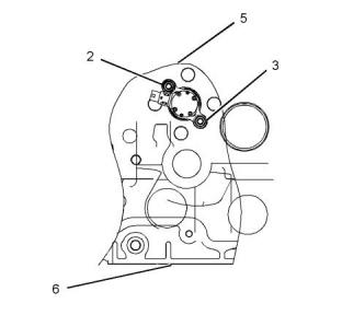
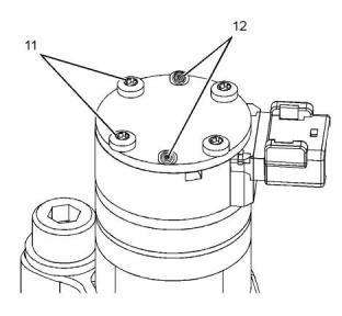
Illustration 9
g01407504
Top view of fuel injector group
Note: The top of the fuel injector group has four bolts
(11) that are used for securing the top cover on the
fuel injector group. There are two holes (12) in the top
of the fuel injector group that are used for assembly
purposes only. Do not install bolts in the two bolt
holes (12).
i02820477
Lifter Group
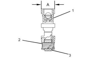
Illustration 11
g01417772
Typical example
(1) Valve bridge
(3) Valve pushrod
Valve lash
Inlet valve.... 0.38 ± 0.08 mm (0.015 ± 0.003 inch)
Exhaust valve...............................0.64 ± 0.08 mm
(0.025 ± 0.003 inch)
Note: Tighten the nut (2) after you set the valve lash.
Illustration 10
g01407530
(2) Torque for the nut ..............30 ± 7 N·m (22 ± 5 lb ft)
(1) Valve lifter insert
(3) Valve lifter roller
(4) Lubricate the bore in the cylinder block for the
valve lifter assemblies with clean engine oil before
installation.
(A) Diameter of a new valve lifter body
.................29.464 ± 0.013 mm (1.1600 ± 0.0005 inch)
(A) Bore diameter of the valve rocker arm
.................28.050 ± 0.013 mm (1.1043 ± 0.0005 inch)
(2) Lubricate the roller pin with clean engine oil.
This document has been printed from SPI2. NOT FOR RESALE
![]()
![]()
![]()
![]()
![]()

![]()
![]()
UENR4509
9
Specifications Section
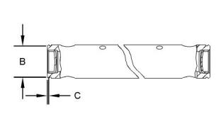
Illustration 12
g01417771
Typical example
(B) Diameter of the new rocker arm shaft
.................28.000 ± 0.013 mm (1.1024 ± 0.0005 inch)
(C) Depth of installation of the two cup plugs from the
end of the rocker arm shaft to the top edge of the cup
plugs .................. 1.25 ± 0.25 mm (0.049 ± 0.010 inch)
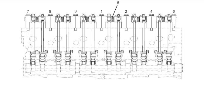
Illustration 13
g01454259
i05998651
Typical example
Note: Tighten the bolts in a numerical sequence that
is shown in Illustration 13 to standard torque.
Valve Mechanism Cover
(5) Spring
Quantity ..............................................................6
Length under test force.........14.5 mm (0.57 inch)
Test force.....................65.0 ± 3.5 N (14.6 ± 0.8 lb)
Approximate free length after test......... 30.75 mm
(1.211 inch)
Outside diameter...............34.80 mm (1.370 inch)
This document has been printed from SPI2. NOT FOR RESALE
![]()
![]()
![]()
![]()
10
UENR4509
Specifications Section
i06000949
Cylinder Head Valves
Illustration 14
g01061297
A typical example of a valve mechanism cover base
Tighten the bolts for the valve cover base in the
sequence that is shown in Illustration 14 to the
following torque...................................28 N·m (21 lb ft)
Illustration 16
g01417779
A typical example of a section view of cylinder head
valves
Note: Fully coat the assembled valve guide inner
diameter with engine oil prior to valve installation.
(1) Inlet valve
Illustration 15
g00728341
A typical example of a valve mechanism cover
Valve stem diameter................. 8.000 ± 0.010 mm
(0.3150 ± 0.0004 inch)
Diameter of valve head..............39.00 ± 0.13 mm
(1.535 ± 0.005 inch)
Note: Some engines may not be equipped with an oil
filler cap that is located on the valve mechanism
cover.
(2) Exhaust valve
Tighten the bolts for the valve mechanism cover in
the sequence that is shown in Illustration 15 to the
following torque...................................20 N·m (15 lb ft)
Valve stem diameter................. 9.441 ± 0.010 mm
(0.3717 ± 0.0004 inch)
Diameter of valve head..............36.00 ± 0.13 mm
(1.417 ± 0.005 inch)
Note: The valve cover seal is cut to size at assembly.
Coat seal joints with Loctite 5940 Black RTV Silicone
Sealant.
(3) Outer Inlet Valve Spring
Length under test force.........42.8 mm (1.69 inch)
Test force...................152.5 ± 7.0 N (34.3 ± 1.6 lb)
Approximate free length after test......... 56.68 mm
(2.231 inch)
This document has been printed from SPI2. NOT FOR RESALE
![]()
![]()
![]()

![]()
![]()
![]()
![]()
UENR4509
11
Specifications Section
Outside diameter................. 21.33 mm (0.84 inch)
Note: Shrink the valve seat inserts by reducing the
temperature. Shrinking the valve seat inserts allows
placement into the counterbore.
(4) Outer Exhaust Valve Spring
Length under test force.....37.70 mm (1.484 inch)
Test force.......................350 ± 17 N (78.7 ± 3.8 lb)
Approximate free length after test......... 57.80 mm
(2.276 inch)
(C) Depth of the bore in the cylinder head for the
valve seat insert
Depth (inlet)..................................9.30 ± 0.05 mm
(0.366 ± 0.002 inch)
Outside diameter...............31.79 mm (1.252 inch)
Depth (exhaust).......................... 10.40 ± 0.05 mm
(0.409 ± 0.002 inch)
(5) Inner Exhaust Valve Spring
Length under test force.........36.5 mm (1.44 inch)
Test force.........................187 ± 8 N (42.0 ± 1.8 lb)
Approximate free length after test......... 57.80 mm
(2.276 inch)
(D) Outside diameter of the valve seat insert
Diameter (inlet)....................... 40.060 ± 0.013 mm
(1.5772 ± 0.0005 inch)
Bore in the cylinder head for the valve seat insert
(inlet) ......................................40.000 ± 0.015 mm
(1.5748 ± 0.0006 inch)
Outside diameter...............23.18 mm (0.913 inch)
(6) Inner Inlet Valve Spring
Length under test force.........44.0 mm (1.73 inch)
Test force.......................305 ± 15 N (68.6 ± 3.3 lb)
Approximate free length after test......... 67.69 mm
(2.665 inch)
Diameter (exhaust) ................37.560 ± 0.013 mm
(1.4787 ± 0.0005 inch)
Bore in the cylinder head for the valve seat insert
(exhaust)................................37.500 ± 0.015 mm
(1.4764 ± 0.0006 inch)
Outside diameter...............28.56 mm (1.124 inch)
Note: Lubricate the bores in the cylinder head for the
valve guides with clean engine oil prior to installation.
(A) Height of the valve guides above the top of the
cylinder head ........... 12.0 ± 0.5 mm (0.47 ± 0.02 inch)
(7) Valve guide (inlet)
Outside diameter.................... 13.030 ± 0.008 mm
(0.5130 ± 0.0003 inch)
Bore in the cylinder head for the valve guide
.......... 13.000 ± 0.013 mm (0.5118 ± 0.0005 inch)
(8) Valve guide (exhaust)
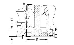
Illustration 18
g03761157
Outside diameter.................... 16.000 ± 0.008 mm
(0.6299 ± 0.0003 inch)
View E-E of Detail B
Bore in the cylinder head for the valve guide
..........15.970 ± 0.013 mm (0.6287 ± 0.0005 inch)
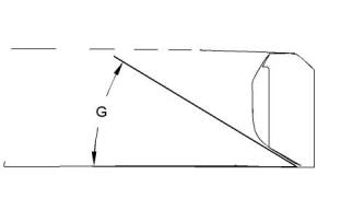
(G) Angle of the face of the valve seat insert
Angle (inlet) ........................30.25 ± 0.25 degrees
Illustration 17
g02137754
Detail B
This document has been printed from SPI2. NOT FOR RESALE
![]()
![]()
![]()
![]()
![]()
12
UENR4509
Specifications Section
Illustration 19
g03761176
View E-E of Detail B
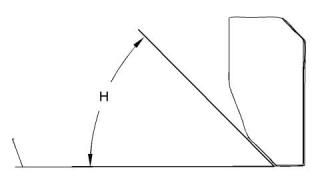
(H) Angle of the face of the valve seat insert
Angle (exhaust) ..................45.00 ± 0.25 degrees
Illustration 21
g03761020
View F-F of Detail B
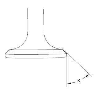
(K) Angle of the face of the valve
Angle (exhaust) ..................45.75 ± 0.25 degrees
Illustration 20
g03761019
View F-F of Detail B
(J) Angle of the face of the valve
Angle (inlet) .......................... 60.5 ± 0.25 degrees
This document has been printed from SPI2. NOT FOR RESALE
![]()
![]()
![]()

![]()
![]()
![]()
![]()
UENR4509
13
Specifications Section
i05985395
Cylinder Head
Illustration 22
g01417896
Typical example
This document has been printed from SPI2. NOT FOR RESALE
![]()
![]()
14
UENR4509
Specifications Section
Note: The top face of the gasket and the top face of
the cylinder block, cylinder liners, and the bottom face
of the gasket and the bottom face of the cylinder head
must be free of oil, fuel, water, and other
contaminants before assembly.
Note: Use clean engine oil to lubricate the threads of
the cylinder head bolts before assembly.
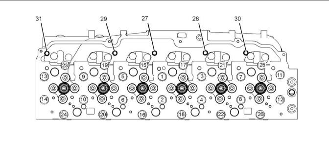
Use the following procedure to tighten the cylinder
head bolts:
1. Torque the bolt (1) through bolt (26) in a numerical
sequence to 130 N·m (95 lb ft).
2. Again torque the bolt (1) through bolt (26) in a
numerical sequence to 130 N·m (95 lb ft).
3. Place a mark on bolt (1) through bolt (26). Rotate
the bolt (1) through bolt (26) in the clockwise
direction in a numerical sequence to 90 degrees
(1/4 turn).
4. Loosen the bolt (1) through bolt (26) in a numerical
sequence to 0 N·m (0 lb ft).
5. Repeat Step 1 through Step 3.
6. Torque the bolt (27) through bolt (31) in a numerical
sequence to 28 N·m (21 lb ft).
Illustration 23
g01417900
Typical example
This document has been printed from SPI2. NOT FOR RESALE
![]()
![]()
UENR4509
15
Specifications Section
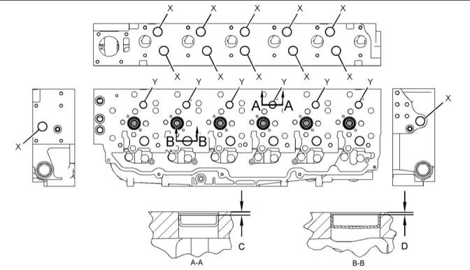
Note: Apply Loctite to the bore of the cup plugs
before assembly.
(C) The cup plugs (Y) are measured from the head
face to the top edge of the plug. Depth of installation
...................................2.0 ± 0.5 mm (0.08 ± 0.02 inch)
(D) The cup plugs (X) are measured from the head
face to the top edge of the plug. Depth of installation
...................................1.5 ± 0.5 mm (0.06 ± 0.02 inch)
Illustration 25
g03763957
Typical example
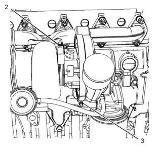
Note: Apply CV60889 Anti-Seize Compound to the
faces of the washers and the nuts before assembly of
the turbocharger.
Illustration 24
g01417914
Typical example
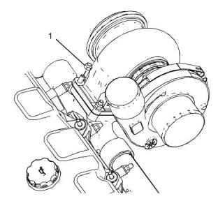
(32) Torque for the plugs................350 N·m (260 lb ft)
(1) Tighten the nuts that fasten the turbocharger to
the exhaust manifold to the following torque.
............................................................54 N·m (40 lb ft)
(E) Height of new cylinder head ..... 130.00 ± 0.15 mm
(5.118 ± 0.006 inch)
Note: The flatness of the cylinder head should be
within 0.15 mm (0.006 inch). The flatness should
also be a maximum of 0.05 mm (0.002 inch) for any
150.00 mm (5.906 inch) span.
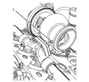
i06004320
Turbocharger
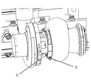
Illustration 26
g03764056
Typical example
(2) Tighten the clamp for the turbine housing to the
following torque................................14 N·m (125 lb in)
(3) Tighten the clamp for the compressor housing to
the following torque............................10 N·m (89 lb in)
This document has been printed from SPI2. NOT FOR RESALE
![]()

![]()
![]()
![]()
![]()
![]()
![]()
16
UENR4509
Specifications Section
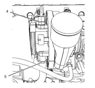
(7) Tighten the bolts to the following torque......28 N·m
(21 lb ft)
i06228941
Turbocharger
(Model PK9)
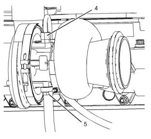
Illustration 27
g03764137
Typical example
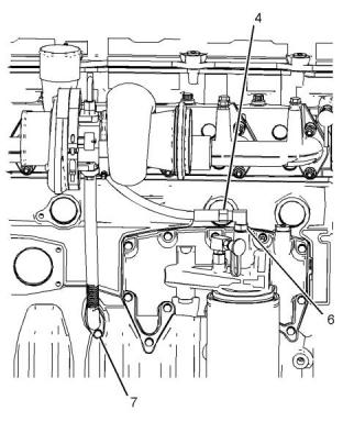
(4) Tighten the tube nuts for hose assembly to the
following torque...................................45 N·m (33 lb ft)
(5) Tighten the bolts to the following torque......28 N·m
(21 lb ft)
Illustration 29
g03863182
Typical example
Wastegate setting with a 1 mm (0.04 inch) movement
for the rod actuator.............................190 kPa (28 psi)
Note: Apply CV60889 Anti-Seize Compound to the
faces of the washers and the nuts before assembly of
the turbocharger.
(1) Tighten the nuts that fasten the turbocharger to
the exhaust manifold to the following torque.
............................................................54 N·m (40 lb ft)
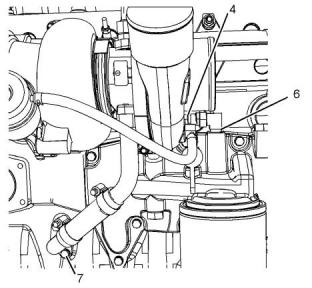
Illustration 28
g03765960
Typical example
(6) Tighten the elbow to the following torque.
............................................................80 N·m (59 lb ft)
This document has been printed from SPI2. NOT FOR RESALE
![]()
![]()
![]()
![]()
![]()
![]()
![]()
UENR4509
17
Specifications Section
Illustration 30
g03863180
Illustration 32
g03863140
Typical example
Typical example
(2) Tighten the clamp for the turbine housing to the
following torque................................14 N·m (125 lb in)
(6) Tighten the elbow to the following torque.
............................................................80 N·m (59 lb ft)
(3) Tighten the clamp for the compressor housing to
the following torque............................10 N·m (89 lb in)
(7) Tighten the bolts to the following torque......28 N·m
(21 lb ft)
i05985469
Air Inlet Elbow
Illustration 31
g03863163
Typical example
(4) Tighten the tube nuts for hose assembly to the
following torque...................................45 N·m (33 lb ft)
(5) Tighten the bolts to the following torque......28 N·m
(21 lb ft)
This document has been printed from SPI2. NOT FOR RESALE
![]()
![]()
![]()
![]()
![]()
![]()
![]()
18
UENR4509
Specifications Section
Illustration 34
g01434396
Typical example
(1) Cylinder head
(2) Torque for the 12 taperlock studs................35 N·m
(26 lb ft)
Illustration 33
g03765697
(3) Torque for the four taperlock studs..............35 N·m
(26 lb ft)
Typical example
(1) Tighten the studs to the following torque.
............................................................28 N·m (21 lb ft)
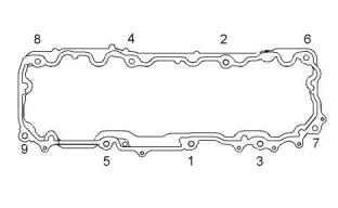
(4) Install the six gaskets with the tabs upward, as
shown.
(2) Tighten the bolts to the following torque......28 N·m
(21 lb ft)
(5) Apply CV60889 Anti-Seize Compound to the
threads of the 12 locknuts before assembly.
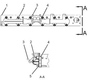
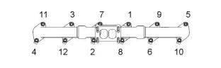
i05983006
Exhaust Manifold
Illustration 35
g01329313
Tightening sequence (typical example)
Tighten the nuts in the numerical sequence that is
shown in Illustration 35 to the following torque.
............................................................55 N·m (41 lb ft)
i02843361
Camshaft
This document has been printed from SPI2. NOT FOR RESALE
![]()
![]()
![]()
![]()
![]()
![]()
![]()
UENR4509
19
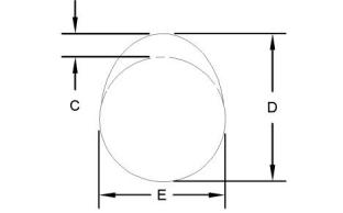
Specifications Section
3. Subtract the base circle (E) from the camshaft lobe
height (D). The difference is the actual camshaft
lobe lift (C).
Maximum permissible difference between the actual
lobe lift and the specified lobe lift of a new camshaft
................................................± 0.10 mm (0.004 inch)
i05985333
Engine Oil Filter Base
Illustration 36
g01417861
(A) Diameter of the four camshaft journals
.................65.126 ± 0.013 mm (2.5640 ± 0.0005 inch)
(B) Thickness of new thrust plate .................... 4.7 mm
(0.19 inch)
End play of a new camshaft................ 0.10 ± 0.08 mm
(0.004 ± 0.003 inch)
Maximum permissible end play of a worn camshaft
...................................................0.46 mm (0.018 inch)
Illustration 38
g01421171
Bolt tightening sequence for oil filter base
Use the tightening sequence that is shown in
Illustration 38 in order to torque the bolts for the oil
filter base.
Illustration 37
g01417862
(C) Specified camshaft lobe lift
Exhaust lobe ...................6.858 mm (0.2700 inch)
Inlet lobe..........................8.655 mm (0.3407 inch)
To find the actual camshaft lobe lift, use the following
procedure:
1. Measure the camshaft lobe height (D).
2. Measure the base circle (E).
This document has been printed from SPI2. NOT FOR RESALE
![]()

![]()
![]()
![]()
![]()
![]()
![]()
20
UENR4509
Specifications Section
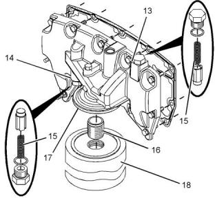
(16) Torque for the hollow stud...........68 N·m (50 lb ft)
(17) Torque for the cover ....................70 N·m (50 lb ft)
i05999049
Engine Oil Pan
Illustration 39
g01421173
Typical example
(13) Oil cooler bypass valve
(14) Oil filter bypass valve
(18) Engine oil filter assembly
(15) Spring
Length under test force.....43.18 mm (1.700 inch)
Test force.........................................43.7 N (9.8 lb)
Free length after test.................. 58.50 ± 0.50 mm
(2.303 ± 0.020 inch)
Illustration 41
g01104928
Outside diameter.........................11 mm (0.4 inch)
Typical example
Apply Loctite 5940 Black RTV Silicone Sealant to
four areas on the sealing surface of the oil pan. The
areas are marked location (Y). The areas are at the
corners of the oil pan in the following locations:
• Connecting joint of the front housing and the front
of the cylinder block
• Connecting joint of the flywheel housing and the
rear of the cylinder block
Make sure that all surfaces are clean and that all
surfaces are free of oil and debris. The sealant must
be applied with a consistent bead of the sealant that
is 5 mm (0.2 inch) diameter in cross section on the
block. The joint must be assembled within 5 minutes
of the application of the sealant.
Use the following procedure to tighten the bolts for
the oil pan.
Tighten the four bolts (X) to the following torque.
............................................................28 N·m (21 lb ft)
Illustration 40
g01421172
Typical example
Start with bolt (Z) and tighten all the remaining bolts in
a counterclockwise sequence.
(A) Length for applying Loctite 575 to the threads of
the hollow stud......... 10.0 ± 1.5 mm (0.39 ± 0.06 inch)
Tighten the bolts to the following torque...........28 N·m
(21 lb ft)
This document has been printed from SPI2. NOT FOR RESALE
![]()
![]()
![]()

![]()
![]()

![]()
![]()
UENR4509
21
Specifications Section
Start again with bolt (Z) and tighten all bolts in a
counterclockwise sequence.
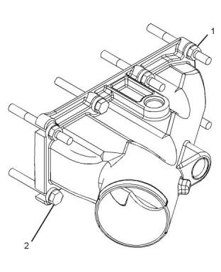
i06003992
Water Temperature Regulator
Tighten the bolts to the following torque...........31 N·m
(23 lb ft)
Housing
Tighten the oil drain plug to the following torque.
............................................................40 N·m (30 lb ft)
i05976165
Crankcase Breather
Illustration 43
g01446597
Typical example
(1) Lubricate the sealing lip of the lip type seal lightly
with glycerin or an approved equivalent.
Illustration 42
g03744941
Typical example
(1) Tighten the bolt to the following torque. ......15 N·m
(11 lb ft)
(2) Tighten the bolt to the following torque. ......55 N·m
(41 lb ft)
(3) Tighten the bolt to the following torque. ......28 N·m
(21 lb ft)
This document has been printed from SPI2. NOT FOR RESALE
![]()

![]()
![]()

![]()
![]()
22
UENR4509
Specifications Section
(1) Lubricate the sealing lip of the lip type seal lightly
with glycerin or an approved equivalent.
Illustration 44
g03763496
Typical example
Illustration 46
g03862995
(2) Tighten the bolts to the following torque......55 N·m
(41 lb ft)
Typical example
(2) Tighten the bolts to the following torque......55 N·m
(41 lb ft)
i06226158
Water Temperature Regulator
Housing
i05982950
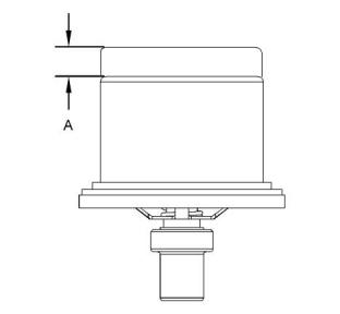
Water Temperature Regulator
Illustration 47
g02542379
, ,Illustration 45
g01417881
Typical example
Typical example
Opening temperature........ 86 to 90 °C (187 to 194 °F)
This document has been printed from SPI2. NOT FOR RESALE
![]()
![]()
![]()

![]()
![]()
![]()
![]()
![]()
![]()
UENR4509
23
Specifications Section
Fully open temperature.........................98 °C (208 °F)
(A) Minimum opening distance at 98 °C (208 °F)
.....................................................10.4 mm (0.41 inch)
This document has been printed from SPI2. NOT FOR RESALE
![]()
24
UENR4509
Specifications Section
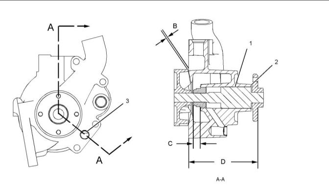
i06004153
Water Pump
Illustration 48
g01354632
Typical example
(1) Shaft assembly
This document has been printed from SPI2. NOT FOR RESALE
![]()
![]()
UENR4509
25
Specifications Section
(2) The bearing must be flush with the edge of the
housing.
(3) The plug must be flush with the edge of the
housing. Refer to Illustration 48 for the correct
orientation of the plug. If necessary, adjust the
orientation of the plug.
(B) Clearance between the pump impeller and the
housing..............0.75 ± 0.25 mm (0.030 ± 0.010 inch)
(C) Working height of the installed water pump seal
assembly...... 11.303 ± 0.127 mm (0.445 ± 0.005 inch)
(D) Distance from the front of the hub to the face of
the housing....122.79 ± 0.30 mm (4.834 ± 0.012 inch)
Note: Refer to Disassembly and Assembly for the
complete procedure for installing the shaft and seal.
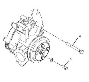
Illustration 49
g03763676
Typical example
(4) Tighten the bolts to the following torque......55 N·m
(41 lb ft)
(5) Tighten the bolts to the following torque......28 N·m
(21 lb ft)
This document has been printed from SPI2. NOT FOR RESALE
![]()
![]()
![]()
26
UENR4509
Specifications Section
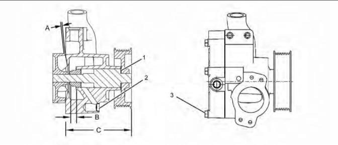
i06226144
Water Pump
(Model PK9)
Illustration 50
g02529516
Typical example
This document has been printed from SPI2. NOT FOR RESALE
![]()
![]()
UENR4509
27
Specifications Section
(A) Clearance between the pump impeller and the
housing..............0.75 ± 0.25 mm (0.030 ± 0.010 inch)
(1) The shaft assembly must be flush with the edge of
the housing.
(2) The plug must be flush with the edge of the
housing. Refer to Illustration 50 for the correct
orientation of the plug. If necessary, adjust the
orientation of the plug.
(3) Tighten the bolts to the following torque......30 N·m
(266 lb in)
(B) Operating height is the following value.
.........................12.19 ± 0.13 mm (0.480 ± 0.005 inch)
(C) Distance from the front face of the pulley to the
face of the housing .........................132.88 ± 0.30 mm
(5.231 ± 0.012 inch)
Illustration 52
g03744524
Typical example
Use the following procedure to tighten the bolts for
the cylinder block cover group:
1. Tighten bolt (1) through bolt (11) to a torque of
28 N·m (21 lb ft). Tighten the bolts in the numerical
sequence that is shown in illustration 52 .
2. Again tighten bolt (1) through bolt (11) to a torque
of 28 N·m (21 lb ft). Tighten the bolts in the
numerical sequence that is shown in illustration 52
.
i06192227
Cylinder Block
Illustration 51
g03862638
Typical example
(4) Tighten the bolts to the following torque......55 N·m
(41 lb ft)
i05975801
Cylinder Block Cover Group