 English
 Espaol
 Franais
 阿拉伯
阿拉伯 中文
中文 Deutsch
 Italiano
 Português
 日本
日本 韩国
韩国 български
 hrvatski
 esky
esky Dansk
Dansk Nederlands
 suomi
suomi Ελληνικ
 印度
印度 norsk
norsk Polski
 Roman
Roman русский
 Svenska
珀金斯Perkins1204E-E44TA、1204E-E44TTA操作保养供应商,珀金斯Perkins1204E-E44TA、1204E-E44TTA操作保养技术价格规格咨询服务,珀金斯Perkins1204E-E44TA、1204E-E44TTA操作保养零配件供应,珀金斯Perkins1204E-E44TA、1204E-E44TTA操作保养售后服务中心,珀金斯Perkins1204E-E44TA、1204E-E44TTA操作保养,珀金斯Perkins1204E-E44TA、1204E-E44TTA操作保养详细的技术参数,

产品中心
珀金斯Perkins1204E-E44TA、1204E-E44TTA操作保养(英文)
详细描述
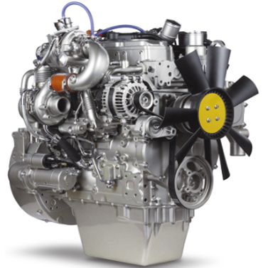
Operation and
Maintenance
Manual
1204E-E44TA and 1204E-E44TTA
Industrial Engines
MK (Engine)
ML (Engine)
This document is printed from SPI². Not for RESALE
![]()
![]()
![]()
![]()
Important Safety Information
Most accidents tha t involve produc t op eration, ma intena nc e and repair are caus ed by failure to
ob serve basic safety rules or precautions . An accident can often be avoided by recog nizing pote ntially
ha za rdous situations before an accident oc curs . A person mus t be alert to pote ntial ha za rds. This
person should also ha ve the ne cessary training, skills and tools to perform the se func tions properly.
Improper operation, lubrication, maintenance or repair of this product can be dangerous and
could result in injury or death.
Do not operate or perform any lubrication, maintenance or repair on this product, until you have
read and understood the operation, lubrication, maintenance and repair information.
Sa fety precautions and warning s are provided in this ma nua l and on the produc t. If the se ha za rd
warning s are not he eded, bod ily injury or death could oc cur to you or to othe r persons .
The ha za rds are identified by the “Safety Alert Symb ol” and followed by a “Signa l Word” suc h as
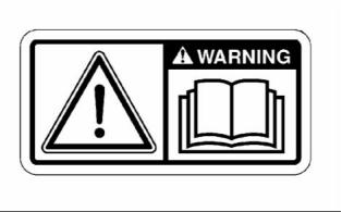
“DANGER”, “WARNING” or “CAUTION”. The Sa fety Alert “WARNING” label is shown below.
The me aning of this safety alert symb ol is as follows:
Attention! Become Alert! Your Safety is Involved.
The me ssage tha t appears und er the warning explains the ha za rd and can be either written or
pictorially presente d.
Op erations tha t ma y caus e produc t dama ge are identified by “NOTICE” labels on the produc t and in
this pub lication.
Perkins cannot anticipate every possible circumstance that might involve a potential hazard. The
warnings in this publication and on the product are, therefore, not all inclusive. If a tool, procedure,
work method or operating technique that is not specifically recommended by Perkins is used,
you must satisfy yourself that it is safe for you and for others. You should also ensure that the
product will not be damaged or be made unsafe by the operation, lubrication, maintenance or
repair procedures that you choose.
The informa tion, specifications , and illustrations in this pub lication are on the basis of informa tion tha t
was available at the time tha t the pub lication was written. The specifications , torque s, pressure s,
me asure me nts , adjustme nts , illustrations , and othe r items can cha ng e at any time. These cha ng es can
affect the service tha t is given to the produc t. Ob tain the comp lete and mos t current informa tion before
you start any job. Pe rkins dealers or Pe rkins distributors ha ve the mos t current informa tion available.
When replacement parts are required for this
product Perkins recommends using Perkins
replacement parts.
Failure to heed this warning can lead to prema-
ture failures, product damage, personal injury or
death.
This document is printed from SPI². Not for RESALE
![]()
![]()
SEBU8605-01
3
Table of Contents
Table of Contents
Maintenance Interval Schedule ............................ 80
Warranty Section
Foreword ................................................................. 4
Warranty Information ........................................... 113
Safety Section
Reference Information Section
Safety Messages .................................................... 5
General Hazard Information ................................... 7
Burn Prevention .................................................... 10
Fire Prevention and Explosion Prevention ............. 11
Crushing Prevention and Cutting Prevention ........ 13
Mounting and Dismounting ................................... 13
High Pressure Fuel Lines ..................................... 13
Before Starting Engine .......................................... 15
Engine Starting ..................................................... 15
Engine Stopping ................................................... 16
Electrical System .................................................. 16
Engine Electronics ................................................ 17
Reference Materials ............................................. 117
Index Section
Index .................................................................... 118
Product Information Section
Model Views ......................................................... 18
Product Identification Information ........................ 27
Operation Section
Lifting and Storage ................................................ 30
Gauges and Indicators .......................................... 34
Features and Controls .......................................... 36
Engine Diagnostics ............................................... 46
Engine Starting ..................................................... 52
Engine Operation .................................................. 55
Engine Stopping ................................................... 57
Cold Weather Operation ....................................... 59
Maintenance Section
Refill Capacities .................................................... 63
Maintenance Recommendations .......................... 78
This document is printed from SPI². Not for RESALE
![]()
![]()
4
SEBU8605-01
Foreword
Foreword
Recommended service should be performed at the
appropriate intervals as indicated in the Maintenance
Interval Schedule. The actual operating environment
of the engine also governs the Maintenance Interval
Schedule. Therefore, under extremely severe,
dusty, wet or freezing cold operating conditions,
more frequent lubrication and maintenance than is
specified in the Maintenance Interval Schedule may
be necessary.
Literature Information
This manual contains safety, operation instructions,
lubrication and maintenance information. This
manual should be stored in or near the engine area
in a literature holder or literature storage area. Read,
study and keep it with the literature and engine
information.
The maintenance schedule items are organized for
a preventive maintenance management program. If
the preventive maintenance program is followed, a
periodic tune-up is not required. The implementation
of a preventive maintenance management program
should minimize operating costs through cost
avoidances resulting from reductions in unscheduled
downtime and failures.
English is the primary language for all Perkins
publications. The English used facilitates translation
and consistency.
Some photographs or illustrations in this manual
show details or attachments that may be different
from your engine. Guards and covers may have
been removed for illustrative purposes. Continuing
improvement and advancement of product design
may have caused changes to your engine which are
not included in this manual. Whenever a question
arises regarding your engine, or this manual, please
consult with your Perkins dealer or your Perkins
distributor for the latest available information.
Maintenance Intervals
Perform maintenance on items at multiples of
the original requirement. We recommend that the
maintenance schedules be reproduced and displayed
near the engine as a convenient reminder. We also
recommend that a maintenance record be maintained
as part of the engine's permanent record.
Safety
Your authorized Perkins dealer or your Perkins
distributor can assist you in adjusting your
maintenance schedule to meet the needs of your
operating environment.
This safety section lists basic safety precautions.
In addition, this section identifies hazardous,
warning situations. Read and understand the basic
precautions listed in the safety section before
operating or performing lubrication, maintenance and
repair on this product.
Overhaul
Major engine overhaul details are not covered in
the Operation and Maintenance Manual except
for the interval and the maintenance items in that
interval. Major repairs should only be carried out by
Perkins authorized personnel. Your Perkins dealer
or your Perkins distributor offers a variety of options
regarding overhaul programs. If you experience
a major engine failure, there are also numerous
after failure overhaul options available. Consult with
your Perkins dealer or your Perkins distributor for
information regarding these options.
Operation
Operating techniques outlined in this manual are
basic. They assist with developing the skills and
techniques required to operate the engine more
efficiently and economically. Skill and techniques
develop as the operator gains knowledge of the
engine and its capabilities.
The operation section is a reference for operators.
Photographs and illustrations guide the operator
through procedures of inspecting, starting, operating
and stopping the engine. This section also includes a
discussion of electronic diagnostic information.
California Proposition 65 Warning
Diesel engine exhaust and some of its constituents
are known to the State of California to cause cancer,
birth defects, and other reproductive harm. Battery
posts, terminals and related accessories contain lead
and lead compounds. Wash hands after handling.
Maintenance
The maintenance section is a guide to engine care.
The illustrated, step-by-step instructions are grouped
by service hours and/or calendar time maintenance
intervals. Items in the maintenance schedule are
referenced to detailed instructions that follow.
This document is printed from SPI². Not for RESALE
![]()
SEBU8605-01
5
Safety Section
Safety Messages
Safety Section
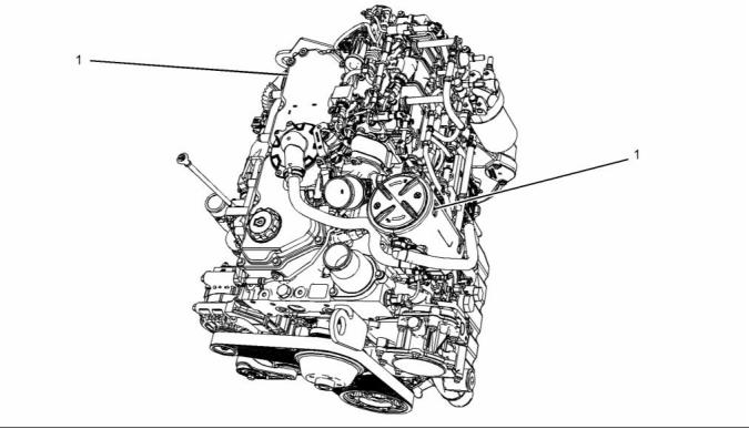
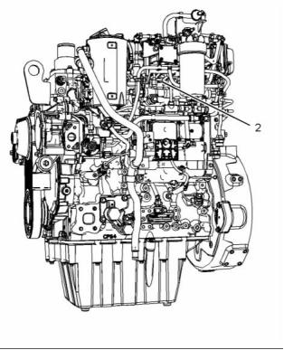
The Universal Warning label (1) is located in two
positions. The warning labels are located on the rear
right side of the valve mechanism cover and located
on the top for the NOx reduction system (NRS).
i04229669
Safety Messages
There may be several specific warning signs on your
engine. The exact location and a description of the
warning signs are reviewed in this section. Please
become familiar with all warning signs.
Ensure that all of the warning signs are legible. Clean
the warning signs or replace the warning signs if
the words cannot be read or if the illustrations are
not visible. Use a cloth, water, and soap to clean
the warning signs. Do not use solvents, gasoline, or
other harsh chemicals. Solvents, gasoline, or harsh
chemicals could loosen the adhesive that secures the
warning signs. The warning signs that are loosened
could drop off the engine.
Replace any warning sign that is damaged or
missing. If a warning sign is attached to a part of the
engine that is replaced, install a new warning sign on
the replacement part. Your Perkins distributor can
provide new warning signs.
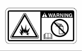
(1) Universal Warning
Do not operate or work on this equipment unless
you have read and understand the instructions
and warnings in the Operation and Maintenance
Manuals. Failure to follow the instructions or
heed the warnings could result in serious injury
or death.
g01154807
Illustration 1
Typical example
This document is printed from SPI². Not for RESALE
![]()
![]()
![]()
![]()
![]()
6
SEBU8605-01
Safety Section
Safety Messages
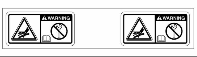
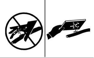
g02406137
Illustration 2
(1) Universal Warning
(2) Hand (High Pressure)
Contact with high pressure fuel may cause fluid
penetration and burn hazards. High pressure fu-
el spray may cause a fire hazard. Failure to fol-
low these inspection, maintenance and service in-
structions may cause personal injury or death.
g02382677
Illustration 3
Typical example
This document is printed from SPI². Not for RESALE
![]()
![]()
![]()
![]()
![]()
SEBU8605-01
7
Safety Section
General Hazard Information
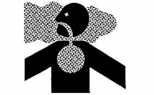
g01154809
i03566024
Illustration 5
Typical example
General Hazard Information
g02406178
Illustration 4
(2) Hand (High Pressure)
The warning label for the Hand (High Pressure)
(2) is a wrap around label that is installed on the
high-pressure fuel line.
Ether Warning
The ether warning label will be installed on the air
cleaner or close to the air cleaner. The location will
depend on the application.
g00104545
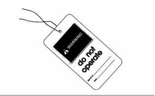
Illustration 6
Attach a “Do Not Operate” warning tag or a similar
warning tag to the start switch or to the controls
before the engine is serviced or before the engine is
repaired. Attach the warning tags to the engine and to
each operator control station. When it is appropriate,
disconnect the starting controls.
Do not use aerosol types of starting aids such as
ether. Such use could result in an explosion and
personal injury.
Do not allow unauthorized personnel on the engine,
or around the engine when the engine is being
serviced.
• Tampering with the engine installation or tampering
with the OEM supplied wiring can be dangerous.
Personal injury, death and/or engine damage could
result.
• Vent the engine exhaust to the outside when the
engine is operated in an enclosed area.
This document is printed from SPI². Not for RESALE
![]()
![]()
![]()
![]()
![]()
![]()
8
SEBU8605-01
Safety Section
General Hazard Information
• If the engine is not running, do not release the
secondary brake or the parking brake systems
unless the vehicle is blocked or unless the vehicle
is restrained.
• For initial start-up of a new engine or for starting an
engine that has been serviced, make provisions to
stop the engine if an overspeed occurs. This may
be accomplished by shutting off the fuel supply
and/or the air supply to the engine.
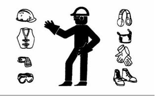
• Wear a hard hat, protective glasses, and other
protective equipment, as required.
• Start the engine from the operator's station (cab).
Never short across the starting motor terminals or
the batteries. This could bypass the engine neutral
start system and/or the electrical system could be
damaged.
• When work is performed around an engine that is
operating, wear protective devices for ears in order
to help prevent damage to hearing.
• Do not wear loose clothing or jewelry that can snag
on controls or on other parts of the engine.
Engine exhaust contains products of combustion
which may be harmful to your health. Always start the
engine and operate the engine in a well ventilated
area. If the engine is in an enclosed area, vent the
engine exhaust to the outside.
• Ensure that all protective guards and all covers are
secured in place on the engine.
• Never put maintenance fluids into glass containers.
Cautiously remove the following parts. To help
prevent spraying or splashing of pressurized fluids,
hold a rag over the part that is being removed.
Glass containers can break.
• Use all cleaning solutions with care.
• Report all necessary repairs.
• Filler caps
• Grease fittings
• Pressure taps
• Breathers
Unless other instructions are provided, perform the
maintenance under the following conditions:
• The engine is stopped. Ensure that the engine can
not be started.
• Drain plugs
• The protective locks or the controls are in the
applied position.
Use caution when cover plates are removed.
Gradually loosen, but do not remove the last two
bolts or nuts that are located at opposite ends of
the cover plate or the device. Before removing the
last two bolts or nuts, pry the cover loose in order to
relieve any spring pressure or other pressure.
• Engage the secondary brakes or parking brakes.
• Block the vehicle or restrain the vehicle before
maintenance or repairs are performed.
• Disconnect the batteries when maintenance
is performed or when the electrical system is
serviced. Disconnect the battery ground leads.
Tape the leads in order to help prevent sparks.
• Disconnect the connector for the unit injector that
is located on the valve cover base. This will help
prevent personal injury from the high voltage to the
unit injectors. Do not come in contact with the unit
injector terminals while the engine is operating.
• Do not attempt any repairs or any adjustments to
the engine while the engine is operating.
g00702020
• Do not attempt any repairs that are not understood.
Use the proper tools. Replace any equipment that
is damaged or repair the equipment.
Illustration 7
• Wear a hard hat, protective glasses, and other
protective equipment, as required.
• When work is performed around an engine that is
operating, wear protective devices for ears in order
to help prevent damage to hearing.
This document is printed from SPI². Not for RESALE
![]()
![]()
SEBU8605-01
9
Safety Section
General Hazard Information
• Do not wear loose clothing or jewelry that can snag
on controls or on other parts of the engine.
• Ensure that all protective guards and all covers are
secured in place on the engine.
• Never put maintenance fluids into glass containers.
Glass containers can break.
• Use all cleaning solutions with care.
• Report all necessary repairs.
Unless other instructions are provided, perform
the maintenance under the following conditions:
g00687600
Illustration 8
• The engine is stopped. Ensure that the engine
cannot be started.
Always use a board or cardboard when you check
for a leak. Leaking fluid that is under pressure can
penetrate body tissue. Fluid penetration can cause
serious injury and possible death. A pin hole leak can
cause severe injury. If fluid is injected into your skin,
you must get treatment immediately. Seek treatment
from a doctor that is familiar with this type of injury.
• Disconnect the batteries when maintenance
is performed or when the electrical system is
serviced. Disconnect the battery ground leads.
Tape the leads in order to help prevent sparks.
• Do not attempt any repairs that are not understood.
Use the proper tools. Replace any equipment that
is damaged or repair the equipment.
Containing Fluid Spillage
NOTICE
Pressurized Air and Water
Care must be taken to ensure that fluids are contained
during performance of inspection, maintenance, test-
ing, adjusting and repair of the product. Be prepared to
collect the fluid with suitable containers before open-
ing any compartment or disassembling any compo-
nent containing fluids.
Pressurized air and/or water can cause debris
and/or hot water to be blown out. This could result in
personal injury.
When pressurized air and/or pressurized water is
used for cleaning, wear protective clothing, protective
shoes, and eye protection. Eye protection includes
goggles or a protective face shield.
Dispose of all fluids according to local regulations and
mandates.
Asbestos Information
The maximum air pressure for cleaning purposes
must be below 205 kPa (30 psi). The maximum
water pressure for cleaning purposes must be below
275 kPa (40 psi).
Fluid Penetration
Pressure can be trapped in the hydraulic circuit long
after the engine has been stopped. The pressure can
cause hydraulic fluid or items such as pipe plugs to
escape rapidly if the pressure is not relieved correctly.
Do not remove any hydraulic components or parts
until pressure has been relieved or personal injury
may occur. Do not disassemble any hydraulic
components or parts until pressure has been relieved
or personal injury may occur. Refer to the OEM
information for any procedures that are required to
relieve the hydraulic pressure.
g00702022
Illustration 9
This document is printed from SPI². Not for RESALE
![]()
![]()
![]()
![]()
![]()
![]()
10
SEBU8605-01
Safety Section
Burn Prevention
Dispose of Waste Properly
Perkins replacement parts that are shipped from
Perkins are asbestos free. Perkins recommends
the use of only genuine Perkins replacement parts.
Use the following guidelines when you handle any
replacement parts that contain asbestos or when you
handle asbestos debris.
Use caution. Avoid inhaling dust that might be
generated when you handle components that contain
asbestos fibers. Inhaling this dust can be hazardous
to your health. The components that may contain
asbestos fibers are brake pads, brake bands, lining
material, clutch plates, and some gaskets. The
asbestos that is used in these components is usually
bound in a resin or sealed in some way. Normal
handling is not hazardous unless airborne dust that
contains asbestos is generated.
g00706404
Illustration 10
If dust that may contain asbestos is present, there
are several guidelines that should be followed:
Improperly disposing of waste can threaten the
environment. Potentially harmful fluids should be
disposed of according to local regulations.
• Never use compressed air for cleaning.
Always use leakproof containers when you drain
fluids. Do not pour waste onto the ground, down a
drain, or into any source of water.
• Avoid brushing materials that contain asbestos.
• Avoid grinding materials that contain asbestos.
• Use a wet method in order to clean up asbestos
materials.
i04224009
Burn Prevention
• A vacuum cleaner that is equipped with a high
efficiency particulate air filter (HEPA) can also be
used.
Do not touch any part of an operating engine
system. The engine, the exhaust, and the engine
aftertreatment system surface temperatures can
reach temperatures of approximately 600° C
(1112 ° F) under normal operating conditions.
• Use exhaust ventilation on permanent machining
jobs.
• Wear an approved respirator if there is no other
way to control the dust.
Allow the engine system to cool before any
maintenance is performed.
• Comply with applicable rules and regulations
for the work place. In the United States, use
Occupational Safety and Health Administration
(OSHA) requirements. These OSHA requirements
can be found in “29 CFR 1910.1001”.
Relieve all pressure in the following systems,
hydraulic system, lubrication system, fuel system,
and the coolant system before the related items are
disconnected.
• Obey environmental regulations for the disposal
of asbestos.
Contact with high pressure fuel may cause fluid
penetration and burn hazards. High pressure fu-
el spray may cause a fire hazard. Failure to fol-
low these inspection, maintenance and service in-
structions may cause personal injury or death.
• Stay away from areas that might have asbestos
particles in the air.
After the engine has stopped, you must wait for 10
minutes in order to allow the fuel pressure to be
purged from the high-pressure fuel lines before any
service or repair is performed on the engine fuel lines.
This document is printed from SPI². Not for RESALE
![]()
![]()

![]()
![]()
SEBU8605-01
11
Safety Section
Fire Prevention and Explosion Prevention
Allow the pressure to be purged in the air system, in
the hydraulic system, in the lubrication system, or
in the cooling system before any lines, fittings, or
related items are disconnected.
Batteries
Electrolyte is an acid. Electrolyte can cause personal
injury. Do not allow electrolyte to contact the skin or
the eyes. Always wear protective glasses for servicing
batteries. Wash hands after touching the batteries
and connectors. Use of gloves is recommended.
Induction System
i03652933
Fire Prevention and Explosion
Prevention
Sulfuric Acid Burn Hazard may cause serious per-
sonal injury or death.
The exhaust gas cooler may contain a small
amount of sulfuric acid. The use of fuel with sul-
fur levels greater than 15 ppm may increase the
amount of sulfuric acid formed. The sulfuric acid
may spill from the cooler during service of the
engine. The sulfuric acid will burn the eyes, skin
and clothing on contact. Always wear the appro-
priate personal protective equipment (PPE) that
is noted on a material safety data sheet (MSDS)
for sulfuric acid. Always follow the directions for
first aid that are noted on a material safety data
sheet (MSDS) for sulfuric acid.
Coolant
When the engine is at operating temperature, the
engine coolant is hot. The coolant is also under
pressure. The radiator and all lines to the heaters or
to the engine contain hot coolant.
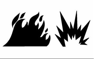
g00704000
Illustration 11
All fuels, most lubricants, and some coolant mixtures
are flammable.
Any contact with hot coolant or with steam can cause
severe burns. Allow cooling system components to
cool before the cooling system is drained.
Flammable fluids that are leaking or spilled onto hot
surfaces or onto electrical components can cause
a fire. Fire may cause personal injury and property
damage.
Check that the coolant level after the engine has
stopped and the engine has been allowed to cool.
After the emergency stop button is operated ensure
that you allow 15 minutes, before the engine covers
are removed.
Ensure that the filler cap is cool before removing the
filler cap. The filler cap must be cool enough to touch
with a bare hand. Remove the filler cap slowly in
order to relieve pressure.
Determine whether the engine will be operated in an
environment that allows combustible gases to be
drawn into the air inlet system. These gases could
cause the engine to overspeed. Personal injury,
property damage, or engine damage could result.
Cooling system conditioner contains alkali. Alkali can
cause personal injury. Do not allow alkali to contact
the skin, the eyes, or the mouth.
If the application involves the presence of combustible
gases, consult your Perkins dealer and/or your
Perkins distributor for additional information about
suitable protection devices.
Oils
Hot oil and hot lubricating components can cause
personal injury. Do not allow hot oil to contact the
skin. Also, do not allow hot components to contact
the skin.
Remove all flammable combustible materials or
conductive materials such as fuel, oil, and debris from
the engine. Do not allow any flammable combustible
materials or conductive materials to accumulate on
the engine.
This document is printed from SPI². Not for RESALE
![]()
![]()
![]()
![]()
12
SEBU8605-01
Safety Section
Fire Prevention and Explosion Prevention
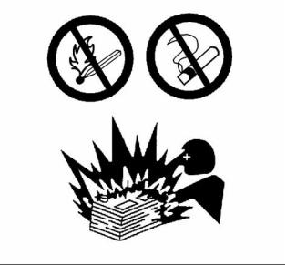
Store fuels and lubricants in correctly marked
containers away from unauthorized persons. Store
oily rags and any flammable materials in protective
containers. Do not smoke in areas that are used for
storing flammable materials.
Do not expose the engine to any flame.
Exhaust shields (if equipped) protect hot exhaust
components from oil or fuel spray in case of a line,
a tube, or a seal failure. Exhaust shields must be
installed correctly.
Do not weld on lines or tanks that contain flammable
fluids. Do not flame cut lines or tanks that contain
flammable fluid. Clean any such lines or tanks
thoroughly with a nonflammable solvent prior to
welding or flame cutting.
Wiring must be kept in good condition. All electrical
wires must be correctly routed and securely attached.
Check all electrical wires daily. Repair any wires
that are loose or frayed before you operate the
engine. Clean all electrical connections and tighten
all electrical connections.
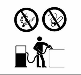
g00704059
Illustration 12
Use caution when you are refueling an engine. Do
not smoke while you are refueling an engine. Do not
refuel an engine near open flames or sparks. Always
stop the engine before refueling.
Eliminate all wiring that is unattached or unnecessary.
Do not use any wires or cables that are smaller than
the recommended gauge. Do not bypass any fuses
and/or circuit breakers.
Arcing or sparking could cause a fire. Secure
connections, recommended wiring, and correctly
maintained battery cables will help to prevent arcing
or sparking.
Contact with high pressure fuel may cause fluid
penetration and burn hazards. High pressure fu-
el spray may cause a fire hazard. Failure to fol-
low these inspection, maintenance and service in-
structions may cause personal injury or death.
After the engine has stopped, you must wait for 10
minutes in order to allow the fuel pressure to be
purged from the high pressure fuel lines before any
service or repair is performed on the engine fuel lines.
g00704135
Illustration 13
Ensure that the engine is stopped. Inspect all lines
and hoses for wear or for deterioration. The hoses
must be correctly routed. The lines and hoses must
have adequate support and secure clamps.
Gases from a battery can explode. Keep any open
flames or sparks away from the top of a battery. Do
not smoke in battery charging areas.
Never check the battery charge by placing a metal
object across the terminal posts. Use a voltmeter or
a hydrometer.
Oil filters and fuel filters must be correctly installed.
The filter housings must be tightened to the correct
torque. Refer to the Disassembly and Assembly
manual for more information.
This document is printed from SPI². Not for RESALE
![]()
![]()
![]()
![]()
![]()
SEBU8605-01
13
Safety Section
Crushing Prevention and Cutting Prevention
Incorrect jumper cable connections can cause
an explosion that can result in injury. Refer to
the Operation Section of this manual for specific
instructions.
i02143194
Crushing Prevention and
Cutting Prevention
Do not charge a frozen battery. This may cause an
explosion.
Support the component correctly when work beneath
the component is performed.
The batteries must be kept clean. The covers
(if equipped) must be kept on the cells. Use the
recommended cables, connections, and battery box
covers when the engine is operated.
Unless other maintenance instructions are provided,
never attempt adjustments while the engine is
running.
Fire Extinguisher
Stay clear of all rotating parts and of all moving
parts. Leave the guards in place until maintenance
is performed. After the maintenance is performed,
reinstall the guards.
Make sure that a fire extinguisher is available. Be
familiar with the operation of the fire extinguisher.
Inspect the fire extinguisher and service the fire
extinguisher regularly. Obey the recommendations
on the instruction plate.
Keep objects away from moving fan blades. The fan
blades will throw objects or cut objects.
Lines, Tubes and Hoses
When objects are struck, wear protective glasses in
order to avoid injury to the eyes.
Do not bend high pressure lines. Do not strike high
pressure lines. Do not install any lines that are
damaged.
Chips or other debris may fly off objects when objects
are struck. Before objects are struck, ensure that no
one will be injured by flying debris.
Leaks can cause fires. Consult your Perkins dealer
or your Perkins distributor for replacement parts.
i04016709
Replace the parts if any of the following conditions
are present:
Mounting and Dismounting
• High pressure fuel line or lines are removed.
• End fittings are damaged or leaking.
• Outer coverings are chafed or cut.
• Wires are exposed.
Do not climb on the engine or the engine
aftertreatment. The engine and aftertreatment have
not been designed with mounting or dismounting
locations.
Refer to the OEM for the location of foot and hand
holds for your specific application.
• Outer coverings are ballooning.
• Flexible part of the hoses are kinked.
• Outer covers have embedded armoring.
• End fittings are displaced.
i03814031
High Pressure Fuel Lines
Make sure that all clamps, guards, and heat shields
are installed correctly. During engine operation, this
will help to prevent vibration, rubbing against other
parts, and excessive heat.
Contact with high pressure fuel may cause fluid
penetration and burn hazards. High pressure fu-
el spray may cause a fire hazard. Failure to fol-
low these inspection, maintenance and service in-
structions may cause personal injury or death.
This document is printed from SPI². Not for RESALE
![]()
![]()
![]()
14
SEBU8605-01
Safety Section
High Pressure Fuel Lines
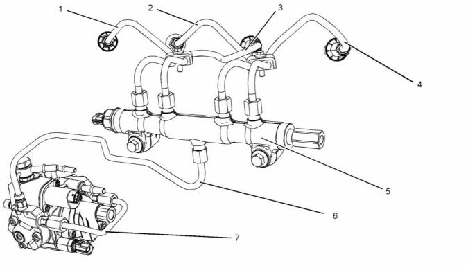
g02067853
Illustration 14
(1) High-pressure line
(2) High-pressure line
(3) High-pressure line
(4) High-pressure line
(5) High-pressure fuel manifold (rail)
(6) High-pressure line
(7) Fuel transfer line that is high pressure
The high-pressure fuel lines are the fuel lines that
are between the high-pressure fuel pump and the
high-pressure fuel manifold and the fuel lines that are
between the fuel manifold and cylinder head. These
fuel lines are different from fuel lines on other fuel
systems.
Do not loosen the high-pressure fuel lines in order
to remove air from the fuel system. This procedure
is not required.
Visually inspect the high-pressure fuel lines before
the engine is started. This inspection should be each
day.
These differences are because of the following items:
If you inspect the engine in operation, always use
the proper inspection procedure in order to avoid
a fluid penetration hazard. Refer to Operation and
Maintenance Manual, “General hazard Information”.
• The high-pressure fuel lines are constantly charged
with high pressure.
• The internal pressures of the high-pressure fuel
lines are higher than other types of fuel system.
• Inspect the high-pressure fuel lines for damage,
deformation, a nick, a cut, a crease, or a dent.
• The high-pressure fuel lines are formed to shape
and then strengthened by a special process.
• Do not operate the engine with a fuel leak. If there
is a leak, do not tighten the connection in order
to stop the leak. The connection must only be
tightened to the recommended torque. Refer to
Disassembly and Assembly, “Fuel injection lines -
Remove and Fuel injection lines - Install”.
Do not step on the high-pressure fuel lines. Do not
deflect the high-pressure fuel lines. Do not bend or
strike the high-pressure fuel lines. Deformation or
damage of the high-pressure fuel lines may cause a
point of weakness and potential failure.
• If the high-pressure fuel lines are torqued correctly,
and the high-pressure fuel lines are leaking the
high-pressure fuel lines must be replaced.
Do not check the high-pressure fuel lines with the
engine or the starting motor in operation. After the
engine has stopped wait 10 minutes in order to allow
the fuel pressure to be purged from the high-pressure
fuel lines. before any service or repair is performed.
This document is printed from SPI². Not for RESALE
![]()
![]()
SEBU8605-01
15
Safety Section
Before Starting Engine
• Ensure that all clips on the high-pressure fuel lines
are in place. Do not operate the engine with clips
that are damaged, missing, or loose.
i03996487
Engine Starting
• Do not attach any other item to the high-pressure
fuel lines.
• Loosened high-pressure fuel lines must be
replaced. Also removed high-pressure fuel lines
must be replaced. Refer to Disassembly and
Assembly manual, “ Fuel Injection Lines - Install”.
Do not use aerosol types of starting aids such as
ether. Such use could result in an explosion and
personal injury.
If a warning tag is attached to the engine start switch,
or to the controls DO NOT start the engine or move
the controls. Consult with the person that attached
the warning tag before the engine is started.
i02813489
Before Starting Engine
All protective guards and all protective covers must
be installed if the engine must be started in order
to perform service procedures. To help prevent an
accident that is caused by parts in rotation, work
around the parts carefully.
Before the initial start-up of an engine that is new,
serviced or repaired, make provision to shut the
engine off, in order to stop an overspeed. This may
be accomplished by shutting off the air and/or fuel
supply to the engine.
Start the engine from the operators compartment or
from the engine start switch.
Overspeed shutdown should occur automatically for
engines that are controlled electronically. If automatic
shutdown does not occur, press the emergency stop
button in order to cut the fuel and/or air to the engine.
Always start the engine according to the procedure
that is described in the Operation and Maintenance
Manual, “Engine Starting” topic in the Operation
Section. Knowing that the correct procedure will help
to prevent major damage to the engine components.
Knowing that the proce, dure will also help to prevent
personal injury.
Inspect the engine for potential hazards.
Before starting the engine, ensure that no one is on,
underneath, or close to the engine. Ensure that the
area is free of personnel.
To ensure that the jacket water heater (if equipped)
and/or the lube oil heater (if equipped) is working
correctly, check the water temperature gauge. Also,
check the oil temperature gauge during the heater
operation.
If equipped, ensure that the lighting system for the
engine is suitable for the conditions. Ensure that all
lights work correctly, if equipped.
All protective guards and all protective covers must
be installed if the engine must be started in order
to perform service procedures. To help prevent an
accident that is caused by parts in rotation, work
around the parts carefully.
Engine exhaust contains products of combustion
which can be harmful to your health. Always start the
engine and operate the engine in a well ventilated
area. If the engine is started in an enclosed area,
vent the engine exhaust to the outside.
Do not bypass the automatic shutoff circuits. Do not
disable the automatic shutoff circuits. The circuits are
provided in order to help prevent personal injury. The
circuits are also provided in order to help prevent
engine damage.
Note: The engine is equipped with a device for cold
starting. If the engine will be operated in very cold
conditions, then an extra cold starting aid may be
required. Normally, the engine will be equipped with
the correct type of starting aid for your region of
operation.
See the Service Manual for repairs and for
adjustments.
These engines are equipped with a glow plug starting
aid in each individual cylinder that heats the intake air
in order to improve starting. Some Perkins engines
may have a cold starting system that is controlled by
the ECM that allows a controlled flow of ether into
the engine. The ECM will disconnect the glow plugs
before the ether is introduced. This system would
be installed at the factory.
This document is printed from SPI². Not for RESALE
![]()
![]()
![]()
16
SEBU8605-01
Safety Section
Engine Stopping
i02234873
Grounding Practices
Engine Stopping
Stop the engine according to the procedure in
the Operation and Maintenance Manual, “Engine
Stopping (Operation Section)” in order to avoid
overheating of the engine and accelerated wear of
the engine components.
Use the Emergency Stop Button (if equipped) ONLY
in an emergency situation. Do not use the Emergency
Stop Button for normal engine stopping. After an
emergency stop, DO NOT start the engine until the
problem that caused the emergency stop has been
corrected.
Stop the engine if an overspeed condition occurs
during the initial start-up of a new engine or an engine
that has been overhauled.
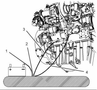
g02407417
To stop an electronically controlled engine, cut the
power to the engine and/or shutting off the air supply
to the engine.
Illustration 15
Typical example
(1) Ground to the battery
(2) Primary position for grounding
(3) Ground to the starting motor
(4) Ground to the engine block
i04231629
Electrical System
Never disconnect any charging unit circuit or battery
circuit cable from the battery when the charging unit
is operating. A spark can cause the combustible
gases that are produced by some batteries to ignite.
To help prevent sparks from igniting combustible
gases that are produced by some batteries, the
negative “−” cable should be connected last from
the external power source to the primary position for
grounding.
Check the electrical wires daily for wires that
are loose or frayed. Tighten all loose electrical
connections before the engine is started. Repair all
frayed electrical wires before the engine is started.
See the Operation and Maintenance Manual for
specific starting instructions.
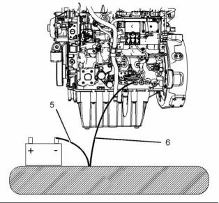
g02407418
Illustration 16
Typical example
(5) Ground to the battery
(6) Ground to the cylinder block
Correct grounding for the engine electrical system
is necessary for optimum engine performance
and reliability. Incorrect grounding will result in
uncontrolled electrical circuit paths and in unreliable
electrical circuit paths.
This document is printed from SPI². Not for RESALE
![]()
![]()
![]()
SEBU8605-01
17
Safety Section
Engine Electronics
Uncontrolled electrical circuit paths can result in
damage to the crankshaft bearing journal surfaces
and to aluminum components.
• Derate
• Shutdown
Engines that are installed without engine-to-frame
ground straps can be damaged by electrical
discharge.
The following monitored engine operating conditions
have the ability to limit engine speed and/or the
engine power:
To ensure that the engine and the engine electrical
systems function correctly, an engine-to-frame
ground strap with a direct path to the battery must be
used. This path may be provided by way of a direct
engine ground to the frame.
• Engine Coolant Temperature
• Engine Oil Pressure
• Engine Speed
The connections for the grounds should be tight and
free of corrosion. The engine alternator must be
grounded to the negative “-” battery terminal with
a wire that is adequate to handle the full charging
current of the alternator.
• Intake Manifold Air Temperature
• Engine Intake Throttle Valve Fault
• Wastegate Regulator
The power supply connections and the ground
connections for the engine electronics should always
be from the isolator to the battery.
• Supply Voltage to Sensors
• Fuel Pressure in Manifold (Rail)
• NOx Reduction System
i03642610
Engine Electronics
• Engine Aftertreatment System
The Engine Monitoring package can vary for different
engine models and different engine applications.
However, the monitoring system and the engine
monitoring control will be similar for all engines.
Tampering with the electronic system installation
or the OEM wiring installation can be dangerous
and could result in personal injury or death and/or
engine damage.
Note: Many of the engine control systems and display
modules that are available for Perkins Engines will
work in unison with the Engine Monitoring System.
Together, the two controls will provide the engine
monitoring function for the specific engine application.
Refer to Troubleshooting for more information on the
Engine Monitoring System.
Electrical Shock Hazard. The electronic unit injec-
tors use DC voltage. The ECM sends this voltage
to the electronic unit injectors. Do not come in
contact with the harness connector for the elec-
tronic unit injectors while the engine is operating.
Failure to follow this instruction could result in
personal injury or death.
This engine has a comprehensive, programmable
Engine Monitoring System. The Electronic Control
Module (ECM) has the ability to monitor the engine
operating conditions. If any of the engine parameters
extend outside an allowable range, the ECM will
initiate an immediate action.
The following actions are available for engine
monitoring control:
• Warning
This document is printed from SPI². Not for RESALE
![]()
![]()
![]()
![]()
![]()
18
SEBU8605-01
Product Information Section
Model Views
Product Information
Section
Model Views
i04231649
Model View Illustrations
The following model views show typical features
of the engine and the aftertreatment system.
Due to individual applications, your engine, or
your aftertreatment may appear different from the
illustrations.
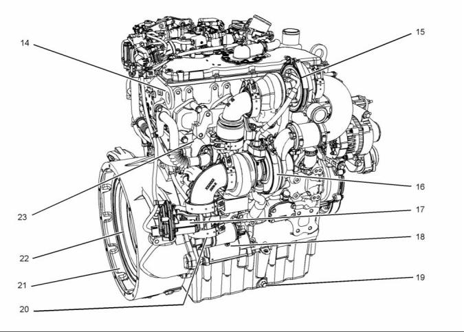
1204E-E44TTA
g02409511
Illustration 17
(1) Front lifting eye
(6) Electronic control module (ECM)
(11) Oil sampling valve
(2) Crankcase breather
(3) NOx Reduction system (NRS)
(4) Primary fuel filter
(7) Fuel priming pump
(8) Oil gauge (dipstick)
(9) Fuel strainer
(12) Oil filler
(13) High-pressure fuel pump
(5) Secondary fuel filter
(10) Oil filter
This document is printed from SPI². Not for RESALE
![]()
![]()

![]()
SEBU8605-01
19
Product Information Section
Model Views
g02409512
Illustration 18
(14) Rear lifting eye
(18) Starting motor
(19) Oil drain plug
(20) Exhaust outlet
(21) Flywheel housing
(22) Flywheel
(23) NRS cooler
(15) High-pressure turbocharger
(16) Low-pressure turbocharger
(17) Back pressure valve
This document is printed from SPI². Not for RESALE
![]()
![]()
20
SEBU8605-01
Product Information Section
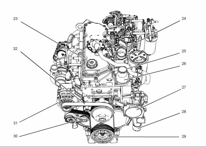
Model Views
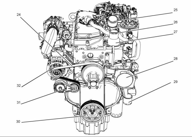
g02409862
Illustration 19
(24) Belt
(25) Air intake
(26) Coolant outlet connection
(27) Thermostat housing
(28) Water pump
(29) Coolant inlet connection
(30) Crankshaft pulley
(31) Belt tensioner
(32) Alternator
This document is printed from SPI². Not for RESALE
![]()
![]()
SEBU8605-01
21
Product Information Section
Model Views
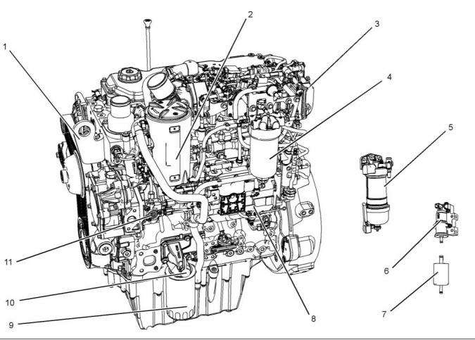
1204E-E44TA
g02407436
Illustration 20
(1) Front lifting eye
(5) Primary fuel filter
(9) Oil filter
(2) Crankcase breather
(3) NOx reduction system (NRS)
(4) Secondary fuel filter
(6) Fuel priming pump
(7) Fuel strainer
(8) Electronic control module (ECM)
(10) Oil sampling valve
(11) High-pressure fuel pump
This document is printed from SPI². Not for RESALE
![]()
![]()
22
SEBU8605-01
Product Information Section
Model Views
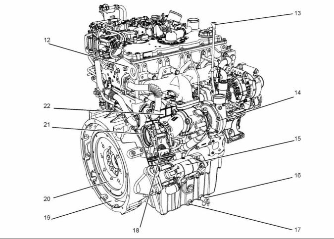
g02407536
Illustration 21
(12) Rear lifting eye
(13) Oil gauge (dipstick)
(14) Turbocharger
(16) Oil drain valve
(17) Oil drain plug
(18) Back pressure valve
(19) Flywheel housing
(20) Flywheel
(21) Exhaust outlet
(22) NRS cooler
(15) Starting motor
This document is printed from SPI². Not for RESALE
![]()
![]()
SEBU8605-01
23
Product Information Section
Model Views
g02407537
Illustration 22
(23) Oil filler
(24) Air intake
(25) Outlet connection for coolant
(26) Thermostat housing
(27) Water pump
(31) Alternator
(32) Belt
(28) Coolant intake connector
(29) Rear lifting eye
(30) Belt tensioner
This document is printed from SPI². Not for RESALE
![]()
![]()
24
SEBU8605-01
Product Information Section
Model Views
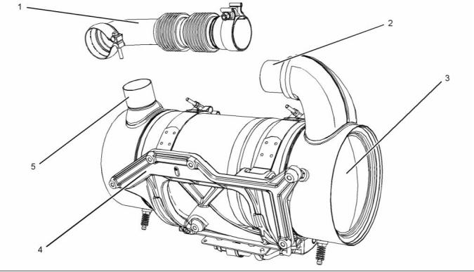
Engine Aftertreatment System
g02483616
Illustration 23
Typical example
(1) Flexible exhaust pipe
(2) Inlet connection
(3) Clean emissions module
(4) Mounting cradle
(5) Outlet connection
• Turbocharged charge cooled
i04340692
Engine Description
Engine Specifications
The front end of the engine is opposite the flywheel
end of the engine. The left and the right sides of the
engine are determined from the flywheel end. The
number 1 cylinder is the front cylinder.
Perkins has designed two versions of the 1204E
industrial engine.
• 1204E-E44TA (MK)
• 1204E-E44TTA (ML)
The 1204E-E44TA (MK) engine is equipped with a
single turbocharger.
The 1204E-E44TTA (ML) engine is equipped with
series turbochargers. An engine that is equipped
with series turbochargers have a low-pressure
turbocharger and a high-pressure turbocharger.
The Perkins 1204E industrial engines have the
following characteristics.
• In-line four cylinder
• Four stroke cycle
This document is printed from SPI². Not for RESALE
![]()
![]()
SEBU8605-01
25
Product Information Section
Model Views
Electronic Engine Features
The engine operating conditions are monitored.
The Electronic Control Module (ECM) controls the
response of the engine to these conditions and to
the demands of the operator. These conditions and
operator demands determine the precise control of
fuel injection by the ECM. The electronic engine
control system provides the following features:
• Engine monitoring
• Engine speed governing
• Control of the injection pressure
• Cold start strategy
• Automatic air/fuel ratio control
• Torque rise shaping
g01187485
Illustration 24
• Injection timing control
(A) Exhaust valves
(B) Inlet valves
• System diagnostics
Table 1
• Aftertreatment low temperature regeneration
1204E-E44TA and 1204E-E44TTA Engine
Specifications
For more information on electronic engine features,
refer to the Operation and Maintenance Manual,
“Features and Controls” topic (Operation Section).
Operating Range (rpm)
800 to 2200
(1)
4 In-Line
Number of Cylinders
Bore
105 mm (4.13 inch)
127 mm (4.99 inch)
Engine Diagnostics
Stroke
Power
The engine has built-in diagnostics in order to ensure
that the engine systems are functioning correctly. The
operator will be alerted to the condition by a “Stop or
Warning” lamp. Under certain conditions, the engine
horsepower and the vehicle speed may be limited.
The electronic service tool may be used to display
the diagnostic codes.
MK
60 to 110 kW
(80.46 to 147.51 hp)
ML
105 to129.5 kW
(140.805 to 173.65 hp)
Aspiration
MK Single Turbocharged
charge cooled
ML Series Turbocharged
charge cooled
There are three types of diagnostic codes: active,
logged, and event.
Most of the diagnostic codes are logged and stored
in the ECM. For additional information, refer to
the Operation and Maintenance Manual, “Engine
Diagnostics” topic (Operation Section).
Compression Ratio
Displacement
16.5:1
4.4 L (268.504 cubic inch)
1-3-4-2
Firing Order
Rotation (flywheel end)
Counterclockwise
The ECM provides an electronic governor that
controls the injector output in order to maintain the
desired engine rpm.
(1) The operating rpm is dependent on the engine rating, the
application, and the configuration of the throttle.
Engine Cooling and Lubrication
The cooling system and lubrication system consists
of the following components:
• Gear-driven centrifugal water pump
This document is printed from SPI². Not for RESALE
![]()
![]()

26
SEBU8605-01
Product Information Section
Model Views
• Water temperature regulator which regulates the
engine coolant temperature
Expected engine life is generally predicted by the
average power that is demanded. The average power
that is demanded is based on fuel consumption of the
engine over a period. Reduced hours of operation
at full throttle and/or operating at reduced throttle
settings result in a lower average power demand.
Reduced hours of operation will increase the length of
operating time before an engine overhaul is required.
• Gear-driven rotor type oil pump
• Oil cooler
The engine lubricating oil is supplied by a rotor type
oil pump. The engine lubricating oil is cooled and the
engine lubricating oil is filtered. The bypass valve
can provide unrestricted flow of lubrication oil to
the engine if the oil filter element should become
plugged.
Aftermarket Products and Perkins
Engines
Perkins does not warrant the quality or performance
Engine efficiency, efficiency of emission controls, and
engine performance depend on adherence to proper
operation and maintenance recommendations.
Engine performance and efficiency also depend on
the use of recommended fuels, lubrication oils, and
coolants. Refer to this Operation and Maintenance
Manual, “Maintenance Interval Schedule” for more
information on maintenance items.
of non-Perkins fluids and filters.
When auxiliary devices, accessories, or consumables
(filters, additives, catalysts,) which are made by other
manufacturers are used on Perkins products, the
Perkins warranty is not affected simply because of
such use.
However, failures that result from the installation
or use of other manufacturers devices,
accessories, or consumables are NOT Perkins
defects. Therefore, the defects are NOT covered
under the Perkins warranty.
Aftertreatment System
The aftertreatment system is approved for use by
Perkins. In order to be emission-compliant only the
approved Perkins aftertreatment system must be
used on a Perkins engine.
Clean Emission Module (CEM)
The CEM comprises of two main components in a
single unit, the Diesel Oxidation Catalyst DOC and
the Diesel Particulate Filter DPF. The function of the
CEM is to ensure that the engine exhaust meets
the required emissions regulation for the country of
operation.
The engine exhaust is connected by a flexible pipe to
the CEM. The exhaust gases pass through the DOC
in order to remove contaminants, carbon monoxide,
and hydrocarbons. The exhaust gases then enter the
DPF where any particulate matter soot and ash will
be trapped.
The CEM uses a passive regeneration process to
ensure that normal operation of the engine removes
the soot. The soot is removed at an equal rate of
which the soot is captured. The ash remains in the
DPF and must be removed at an engine overhaul.
Engine Service Life
Engine efficiency and maximum utilization of engine
performance depend on the adherence to proper
operation and maintenance recommendations. In
addition, use recommended fuels, coolants, and
lubricants. Use the Operation and Maintenance
Manual as a guide for required engine maintenance.
This document is printed from SPI². Not for RESALE
![]()
SEBU8605-01
27
Product Information Section
Product Identification Information
Product Identification
Information
i03865704
Plate Locations and Film
Locations
(Engine Aftertreatment System
)
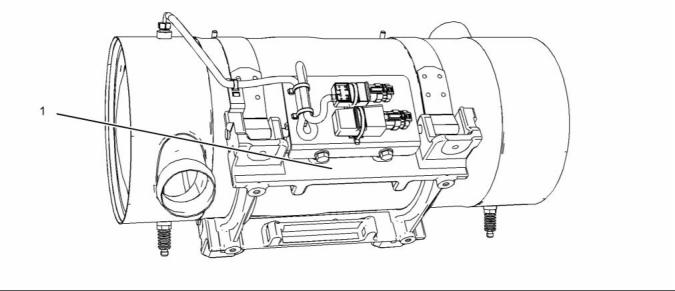
g02109488
Illustration 25
Typical example
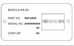
The module arrangement exhaust plate is installed
on the mounting plate (1). The location of the
arrangement plate mounting plate can alter
depending on the application.
Record the information that is on the plate. This
information identifies the engine aftertreatment
system. This information will be required by your
Perkins distributor. The information is essential in
order to be emissions complaint.
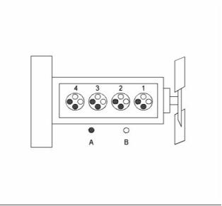
g02109493
Illustration 26
Module Arrangement Exhaust Plate
This document is printed from SPI². Not for RESALE
![]()
![]()
![]()
28
SEBU8605-01
Product Information Section
Product Identification Information
i03827189
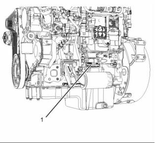
Serial Number Plate (1)
Plate Locations and Film
Locations
(Engine)
The engine serial number plate is located on the
left side of the cylinder block to the rear of the front
engine mounting.
g02101733
Illustration 28
Serial number plate
i03867276
Reference Numbers
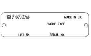
g02077373
Illustration 27
Information for the following items may be needed to
order parts. Locate the information for your engine.
Record the information in the appropriate space.
Make a copy of this list for a record. Keep the
information for future reference.
Perkins engines are identified by an engine serial
number.
An example of an engine number is
ML*****U000001U.
Record for Reference
***** ____________________The list number for the engine
ML _____________________________________The type of engine
U ____________________________Built in the United Kingdom
000001 ___________________________Engine Serial Number
U _____________________________________Year of Manufacture
Engine Model _______________________________________________
Engine Serial number _____________________________________
Engine Low Idle rpm ______________________________________
Engine Full Load rpm _____________________________________
Primary Fuel Filter _________________________________________
Water Separator Element ________________________________
Secondary Fuel Filter Element __________________________
Lubrication Oil Filter Element ___________________________
Auxiliary Oil Filter Element _______________________________
Total Lubrication System Capacity _____________________
Total Cooling System Capacity _________________________
Air Cleaner Element _______________________________________
Perkins dealers or Perkins distributors need all of
these numbers in order to determine the components
that were included with the engine. This information
permits accurate identification of replacement part
numbers.
The numbers for fuel setting information for electronic
engines are stored within the flash file. These
numbers can be read by using the electronic service
tool.
This document is printed from SPI². Not for RESALE
![]()
![]()
![]()
SEBU8605-01
29
Product Information Section
Product Identification Information
Drive Belt ____________________________________________________
Engine Aftertreatment System
Part Number ________________________________________________
Serial Number ______________________________________________
i04274850
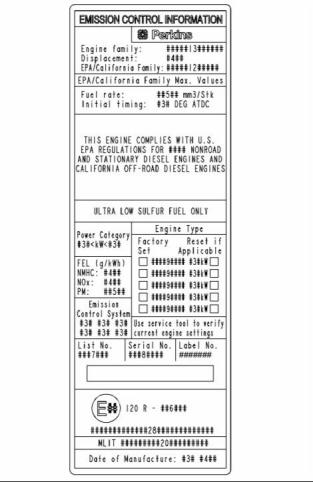
Emissions Certification Film
An emission label is installed on the front gear cover.
Note: A second emission label will be supplied with
the engine. If necessary, the second emission label
will be installed on the application by the original
equipment manufacturer.
g02443596
Illustration 29
Typical example
This document is printed from SPI². Not for RESALE
![]()
![]()
30
SEBU8605-01
Operation Section
Lifting and Storage
Operation Section
Lifting and Storage
Some removals require lifting the fixtures in order to
obtain correct balance and safety.
To remove the engine ONLY, use the lifting eyes that
are on the engine.
Lifting eyes are designed and installed for specific
engine arrangements. Alterations to the lifting eyes
and/or the engine make the lifting eyes and the lifting
fixtures obsolete. If alterations are made, ensure
that correct lifting devices are provided. Consult
your Perkins dealer or your Perkins distributor for
information regarding fixtures for correct engine
lifting.
i04332972
Product Lifting
(Engine)
g01097527
Illustration 30
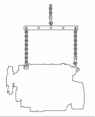
NOTICE
Never bend the eyebolts and the brackets. Only load
the eyebolts and the brackets under tension. Remem-
ber that the capacity of an eyebolt is less as the angle
between the supporting members and the object be-
comes less than 90 degrees.
When it is necessary to remove a component at an
angle, only use a link bracket that is properly rated for
the weight.
Use a hoist to remove heavy components. Use
an adjustable lifting beam to lift the engine. All
supporting members (chains and cables) should be
parallel to each other. The chains and cables should
be perpendicular to the top of the object that is being
lifted.
This document is printed from SPI². Not for RESALE
![]()
![]()
![]()
![]()
![]()
SEBU8605-01
31
Operation Section
Lifting and Storage
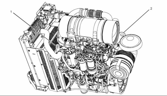
Industrial Open Power Unit
g02488437
Illustration 31
Typical example
(1) Location of front lifting eye
(2) Location of rear lifting eye
This document is printed from SPI². Not for RESALE
![]()
![]()
32
SEBU8605-01
Operation Section
Lifting and Storage
i04195469
i04084189
Product Lifting
(Clean Emission Module)
Product Storage
(Engine and Aftertreatment)
Perkins are not responsible for damage which may
occur when an engine is in storage after a period in
service.
Your Perkins dealer or your Perkins distributor can
assist in preparing the engine for extended storage
periods.
Condition for Storage
The engine must be stored in a water proof building.
The building must be kept at a constant temperature.
Engines that are filled with Perkins ELC will have
coolant protection to an ambient temperature of
−36° C (−32.8° F). The engine must not be subjected
to extreme variations in temperature and humidity.
Storage Period
An engine can be stored for up to 6 months provided
all the recommendation are adhered to.
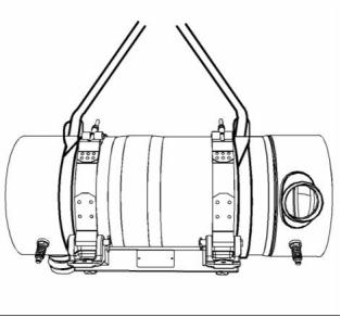
g02385036
Illustration 32
Ensure that the correct clothing is worn, refer to
this Operation and Maintenance Manual, “General
Hazard Information”.
Storage Procedure
Keep a record of the procedure that has been
completed on the engine.
The weight of the clean emission module (CEM)
when laden is approximately 50 kg (110 lb). Two
suitable double looped slings are required in order to
lift the CEM. Also a suitable hoist will be required in
order to remove and install the assembly.
Note: Do not store an engine that has biodiesel in
the fuel system.
1. Ensure that the engine is clean and dry.
The slings must be attached to the CEM in the
positions as shown in illustration 32.
a. If the engine has been operated using biodiesel,
the system must be drained and new filters
installed. The fuel tank will require flushing.
Ensure that the slings only contact the body of the
CEM. A test lift may be required in order to achieve
the correct balance of the assembly.
b. Fill the fuel system with an ultra low sulfur fuel.
For more information on acceptable fuels refer
to this Operation and Maintenance Manual,
“Fluid recommendations”. Operate the engine
for 15 minutes in order to remove all biodiesel
from the system.
Some applications may require a frame or jig in order
to lift the CEM. A frame or jig must only be connected
to the cradle of the CEM. Refer to the OEM for more
information.
2. Drain any water from the primary filter water
separator. Ensure that the fuel tank is full.
3. The engine oil will not need to be drained in
order to store the engine. Provided the correct
specification of engine oil is used the engine
can be stored for up to 6 months. For the
correct specification of engine oil refer to this
Operation and Maintenance Manual, “Fluid
recommendations”.
This document is printed from SPI². Not for RESALE
![]()
![]()
SEBU8605-01
33
Operation Section
Lifting and Storage
4. Remove the drive belt from the engine.
Sealed Coolant System
Ensure that the cooling system is filled with Perkins
ELC, or an antifreeze that meets “ASTM D6210”
specification.
Open Cooling System
Ensure that all cooling drain plugs have been
opened. Allow the coolant to drain. Install the drain
plugs. Place a vapor phase inhibitor into the system.
The coolant system must be sealed once the vapor
phase inhibitor has been introduced. The effect of the
vapor phase inhibitor will be lost if the cooling system
is open to the atmosphere.
For maintenance procedures ref to this Operation
and Maintenance Manual.
Aftertreatment
No special procedures are required. The exhaust
outlet of the aftertreatment should be capped. Before
storing, the engine and the aftertreatment must be
enclosed in a cover.
Monthly Checks
The crankshaft must be rotated in order to change
the spring loading on the valve train. Rotate
the crankshaft more than 180 degrees. Visibly
check for damage or corrosion to the engine and
aftertreatment.
Ensure that the engine and aftertreatment are
covered completely before storage. Log the
procedure in the record for the engine.
This document is printed from SPI². Not for RESALE
![]()
34
SEBU8605-01
Operation Section
Gauges and Indicators
Gauges and Indicators
1. Remove the load.
2. Stop the engine.
i04220531
3. Check and maintain the oil level.
Gauges and Indicators
Jacket Water Coolant Temperature –
Typical temperature range is 82° to 94°C
(179.6° to 201.2°F). This temperature range
will vary according to engine load and the ambient
temperature.
Your engine may not have the same gauges or all of
the gauges that are described. For more information
about the gauge package, see the OEM information.
A 100 kPa (14.5 psi) radiator cap must be installed
on the cooling system. The maximum temperature
for the cooling system is 108° C (226.4° F). This
temperature is measured at the outlet for the
water temperature regulator. The engine coolant
temperature is regulated by the engine sensors
and the engine ECM. This programming cannot be
altered. An engine derate can occur if the maximum
engine coolant temperature is exceeded.
Gauges provide indications of engine performance.
Ensure that the gauges are in good working order.
Determine the normal operating range by observing
the gauges over a period of time.
Noticeable changes in gauge readings indicate
potential gauge or engine problems. Problems may
also be indicated by gauge readings that change
even if the readings are within specifications.
Determine and correct the cause of any significant
change in the readings. Consult your Perkins
distributor for assistance.
If the engine is operating above the normal range,
reduce the engine load. If high coolant temperatures
are a frequent event, perform the following
procedures:
Some engine applications are equipped with Indicator
Lamps. Indicator lamps can be used as a diagnostic
aid. There are two lamps. One lamp has an orange
lens and the other lamp has a red lens.
1. Reduce the load and the engine rpm.
2. Determine if the engine must be shut down
immediately or if the engine can be cooled by
reducing the load.
These indicator lamps can be used in two ways:
• The indicator lamps can be used to identify the
current operational status of the engine. The
indicator lamps can also indicate that the engine
has a fault. This system is automatically operated
via the ignition switch.
3. Inspect the cooling system for leaks. If necessary,
consult your Perkins distributor for assistance.
Tachometer – This gauge indicates engine
speed (rpm). When the throttle control lever
is moved to the full throttle position without
load, the engine is running at high idle. The engine is
running at the full load rpm when the throttle control
lever is at the full throttle position with maximum
rated load.
• The indicator lamps can be used to identify active
diagnostic codes. This system is activated by
pressing the Flash Code button.
Refer to the Troubleshooting Guide, “Indicator
Lamps” for further information.
NOTICE
Operation at speeds exceeding high idle rpm should
be kept to a minimum. Overspeeding can result in se-
rious damage to the engine.
NOTICE
If no oil pressure is indicated, STOP the engine. If
maximum coolant temperature is exceeded, STOP
the engine. Engine damage can result.
Ammeter – This gauge indicates the
amount of charge or discharge in the
battery charging circuit. Operation of the
indicator should be to the “+” side of “0” (zero).
Engine Oil Pressure – The oil pressure
should be greatest after a cold engine is
started. The typical engine oil pressure with
SAE10W40 is 350 to 450 kPa ( 50 to 65 psi) at rated
rpm.
Fuel Level – This gauge indicates the fuel
level in the fuel tank. The fuel level gauge
operates when the “START/STOP” switch
is in the “on” position.
A lower oil pressure is normal at low idle. If the load
is stable and the gauge reading changes, perform
the following procedure:
This document is printed from SPI². Not for RESALE
![]()
![]()
![]()
![]()
![]()
![]()
![]()
![]()
![]()
![]()
SEBU8605-01
35
Operation Section
Gauges and Indicators
• Oil pressure
Service Hour Meter – The gauge indicates
total operating hours of the engine.
• Intake temperature
• Intake pressure
• Atmospheric pressure
• Fuel temperature
Indicator Lamps
There is four indicator lamps that are available.
• Shutdown Lamp
• Warning Lamp
• Wait to Start Lamp
• Low Oil Pressure Lamp
For information, refer to this manual, “Monitoring
System (Table for the Indicator Lamps)” for the
sequence of operation of the shutdown lamp and the
warning lamp.
The function of the wait to start lamp is automatically
controlled at engine start-up.
The function of the low oil pressure lamp is controlled
by the engine ECM. If low oil pressure is detected,
the lamp will be illuminated. The reason for the
illumination of the low-pressure lamp should be
investigated immediately.
All lamps will illuminate for 2 seconds in order to
check that the lamps are functioning when the
keyswitch is turned to the ON position. If any of the
lamps stay illuminated, the reason for illumination
should be investigated immediately.
Instrument panels and Displays
In order to monitor the engine a wide verity of
instrument panels are available. These instrument
panels can contain the indicator lamps and the
gauges for the application.
Also available are mini power displays and
performance monitors. These displays and monitors
can show the operator the following engine
information.
• The system configuration parameters
• The customer specified parameters
• Diagnostic codes
• Event codes
• Coolant temperature
• Oil temperature
This document is printed from SPI². Not for RESALE
![]()
![]()
36
SEBU8605-01
Operation Section
Features and Controls
Features and Controls
Programmable Options and
Systems Operation
i04340829
Monitoring System
If the Warning/Derate/Shutdown mode has been
selected and the warning indicator activates,
bring the engine to a stop whenever possible. De-
pending on the application, special precautions
should be taken to avoid personal injury.
If the Shutdown mode has been selected and the
warning indicator activates, engine shutdown may
take as little as 20 seconds from the time the warn-
ing indicator is activated. Depending on the ap-
plication, special precautions should be taken to
avoid personal injury. The engine can be restarted
following shutdown for emergency maneuvers, if
necessary.
The engine can be programmed to the following
modes:
“Warning”
The orange “Warning” lamp will turn “ON” and the
warning signal is activated continuously in order to
alert the operator that one or more of the engine
parameters is not within normal operating range.
NOTICE
The Engine Monitoring System is not a guarantee
against catastrophic failures. Programmed delays
and derate schedules are designed to minimize false
alarms and provide time for the operator to stop the
engine.
“Derate”
The orange warning lamp will be flashing. After the
warning, the engine power will be derated.
The engine will be derated if the engine exceeds
preset operational limits. The engine derate is
achieved by restricting the amount of fuel that is
available for each injection. The amount of this
reduction of fuel is dependent on the severity of the
fault that has caused the engine derate, typically up
to a limit of 50%. This reduction in fuel results in a
predetermined reduction in engine power.
The following parameters are monitored:
• Coolant temperature
• Intake manifold air temperature
• Intake manifold air pressure
• Oil pressure
“Shutdown”
• Pressure in the fuel rail
The orange warning lamp will be flashing and the red
shutdown lamp will be on solid. After the warning,
the engine power will be derated. The engine will
continue at the rpm of the set derate until a shutdown
of the engine occurs. The engine can be restarted
after a shutdown for use in an emergency.
• Engine speed/timing
• Fuel temperature
• Atmospheric pressure (Barometric pressure)
• The Inlet pressure and outlet pressure of the NOx
reduction system
A shutdown of the engine may occur in as little
as 20 seconds. The engine can be restarted after
a shutdown for use in an emergency. However,
the cause of the initial shutdown may still exist.
The engine may shut down again in as little as 20
seconds.
• Temperature of the NOx reduction system
• Water in fuel switch
• The amount of soot in the Diesel particulate filter
If there is a signal for high coolant temperature,
there will be a 2 second delay in order to verify the
condition.
If there is a signal for low oil pressure, there will be a
2 second delay in order to verify the condition.
This document is printed from SPI². Not for RESALE
![]()
![]()
![]()
![]()
![]()
![]()
![]()
&, nbsp;
SEBU8605-01
37
Operation Section
Features and Controls
For information on the operation of the warning lamps
and the shutdown lamp, refer to this Operation and
Maintenance Manual, “ Monitoring System (Table
for Indicator Lamps)”. For each of the programmed
modes, refer to Troubleshooting Guide, “Indicator
Lamps” for more information on Indicator Lamps.
For more information or assistance for repairs,
consult your Perkins distributor or your Perkins
dealer.
This document is printed from SPI². Not for RESALE
![]()
38
SEBU8605-01
Operation Section
Features and Controls
i04201172
Monitoring System
(Table for the Indicator lamps)
Note: When in operation the amber warning lamp
has three states, solid, flashing, and fast flashing.
The sequence is to give a visual indication of the
importance of the warning. Some application can
have an audible warning installed.
Ensure that the engine maintenance is carried out at
the correct intervals. A lack of maintenance can result
in illumination of the warning lamp. For the correct
intervals of maintenance, refer to the Operation
and Maintenance Manual, “Maintenance Interval
Schedule”.
Table 2
Warning
Lamp
Shutdown
Lamp
Lamp State
Description of the Indication
Engine Status
The keyswitch is in the ON position but
On
On
Lamp Check
When the keyswitch is moved to the
ON position, the lamps come on for 2 the engine has not yet been cranked.
seconds and the lamps will then go
off.
Off
Off
Off
No Faults
Warning
With the engine in operation, there
are no active warnings, diagnostic
codes, or event codes.
The engine is operating with no detected
faults.
On Solid
Level 1 warning
The engine is operating normally but
there is one or more faults with the
electronic management system for the
engine.
Flashing
Flashing
Off
On
Warning
Level 2 warning
The engine continues to be operated,
but the level of importance of the
warning has increased.
Depending on the particular fault and
the severity the engine may be de-rated.
The engine could be damaged if
continued to be operated.
Engine
Shutdown
Level 3 warning
The engine is either shutdown or an
engine shutdown is imminent. One or
more monitored engine parameters
have exceeded the limit for an engine
shutdown. This pattern of lamps can be
caused by the detection of a serious
active diagnostic code.
If both the warning lamp and the
shutdown lamp are in operation, this
issue indicates one of the following
conditions.
1. One or more of the shutdown
values for the engine protection
strategy has been exceeded.
2. A serious active diagnostic code
has been detected.
After a short time period, the engine
may shut down.
This document is printed from SPI². Not for RESALE
![]()

SEBU8605-01
39
Operation Section
Features and Controls
i04215952
Sensors and Electrical
Components
(Aftertreatment)
The illustration within the section shows the
typical locations of the sensors and other electrical
components on the industrial engine. Specific engine
aftertreatment systems may appear different due to
the application.
g02395776
Illustration 33
(1) Temperature Sensor
(2) Connector for Temperature Sensor
(3) Soot Sensor Connection
(4) Aftertreatment Identification Module
(5) Soot Sensor Connection
(6) Soot Sensor
Note: The location of the soot sensor will depend
i04238530
on the application.
Sensors and Electrical
Components
The illustration within the section shows the
typical locations of the sensors and other electrical
components on a 1204 Industrial engine. Specific
engines may appear different due to the application.
This document is printed from SPI². Not for RESALE
![]()
![]()
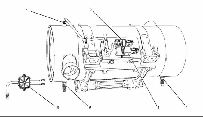
40
SEBU8605-01
Operation Section
Features and Controls
g02411637
Illustration 34
(1) Coolant Temperature Sensor
(2) Fuel Pressure Sensor (Fuel Rail
Pressure Sensor)
(3) Intake Manifold Air Temperature Sensor
(4) Intake Manifold Pressure Sensor
(5) Electronic Control Module (ECM)
(6) Atmospheric Pressure Sensor
(Barometric Pressure Sensor)
(7) Primary Speed/Timing sensor
(Crankshaft Position Sensor)
(8) Diagnostic Connector
(9) Oil Pressure Sensor
(10) Fuel Temperature Sensor
(11) Solenoid for the High Pressure Fuel
Pump
(13) Inlet Pressure Sensor for the NOx
Reduction System (NRS)
(14) Outlet Pressure Sensor for the NRS
(15) Control Valve for the NRS
(16) Temperature Sensor for the NRS
(12) Wastegate Regulator
This document is printed from SPI². Not for RESALE
![]()
![]()
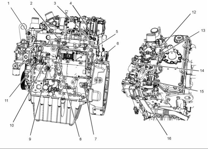
SEBU8605-01
41
Operation Section
Features and Controls
g02411837
Illustration 35
(17) Back Pressure Valve
(18) Alternator
(19) Secondary Speed/Timing Sensor
(Camshaft Position Sensor)
(20) Starting Motor
(21) Water in Fuel Switch
(22) Oil Level Switch (if Equipped)
(23) Electric Priming Pump
g02413838
Illustration 36
(1) Coolant Temperature Sensor
(2) Fuel Pressure Sensor (Fuel Rail
Pressure Sensor)
(3) Intake Manifold Air Temperature Sensor
(4) Intake Manifold Pressure Sensor
(5) Electronic Control Module (ECM)
This document is printed from SPI². Not for RESALE
![]()
![]()
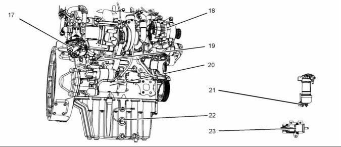
![]()
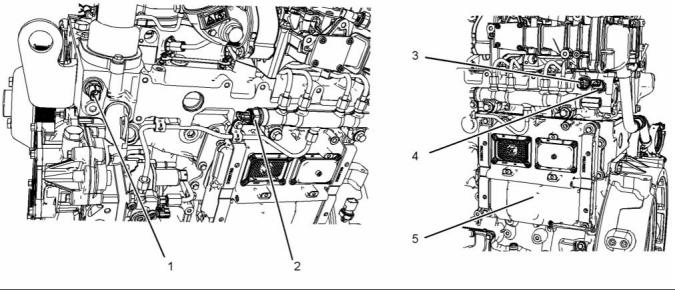
42
SEBU8605-01
Operation Section
Features and Controls
g02413839
Illustration 37
(6) Atmospheric Pressure Sensor
(Barometric Pressure Sensor)
(7) Primary Speed/Timing sensor
(Crankshaft Position Sensor)
(8) Diagnostic Connector
(9) Oil Pressure Sensor
g02413840
Illustration 38
(10) Fuel Temperature Sensor
(11) Solenoid for the High Pressure Fuel
Pump
(12) Wastegate Regulator
(13) Inlet Pressure Sensor for the NOx
Reduction System (NRS)
(14) Outlet Pressure Sensor for the NRS
This document is printed from SPI². Not for RESALE
![]()
![]()
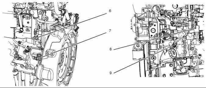
![]()
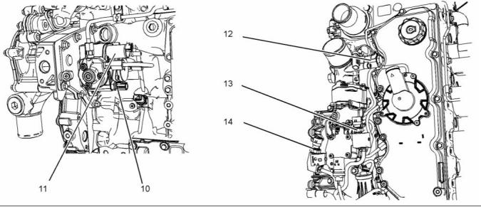
SEBU8605-01
43
Operation Section
Features and Controls
g02414076
Illustration 39
(15) Control Valve for the NRS
(16) Temperature Sensor for the NRS
(17) Back Pressure Valve
g02414077
Illustration 40
(18) Alternator
(19) Secondary Speed/Timing Sensor
(Camshaft Position Sensor)
(20) Starting Motor
This document is printed from SPI². Not for RESALE
![]()
![]()
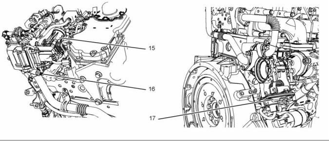
![]()
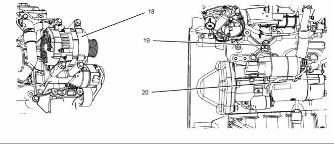
44
SEBU8605-01
Operation Section
Features and Controls
g02414506
Illustration 41
(21) Water in Fuel Switch
(22) Oil Level Switch (if Equipped)
(23) Electric Priming Pump
• Types and locations of the shutoff
i04372832
Engine Shutoffs and Engine
Alarms
• Conditions which cause each shutoff to function
• The resetting procedure that is required to restart
the engine
Alarms
Shutoffs
The alarms are electrically operated. The operation
of the alarms is controlled by the ECM.
The shutoffs are electrically operated or mechanically
operated. The electrically operated shutoffs are
controlled by the ECM.
The alarm is operated by a sensor or by a switch.
When the sensor or the switch is activated, a signal
is sent to the ECM. An event code is created by
the ECM. The ECM will send a signal in order to
illuminate the lamp.
Shutoffs are set at critical levels for the following
items:
• Operating temperature
• Operating pressure
• Operating level
Your engine may be equipped with the following
sensors or switches:
Coolant level – The low coolant level switch
indicates when the coolant level is low.
• Operating rpm
Coolant temperature – The coolant temperature
sensor indicates high jacket water coolant
temperature.
The particular shutoff may need to be reset before
the engine will start.
NOTICE
Intake manifold air temperature – The intake
manifold air temperature sensor indicates high intake
air temperature.
Always determine the cause of the engine shutdown.
Make necessary repairs before attempting to restart
the engine.
Be familiar with the following items:
This document is printed from SPI². Not for RESALE
![]()
![]()
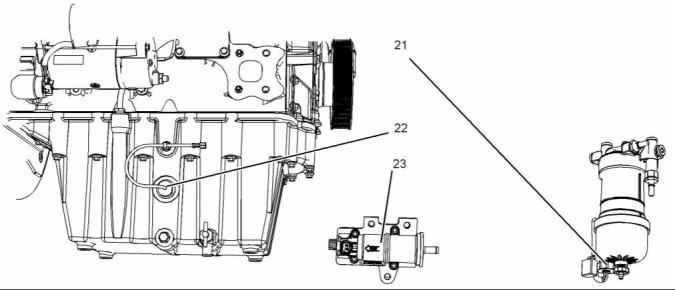
![]()
![]()
SEBU8605-01
45
Operation Section
Features and Controls
Intake manifold pressure – The intake manifold
pressure sensor checks the rated pressure in the
engine manifold.
i03554501
Overspeed
Fuel rail pressure – The fuel rail pressure sensor
checks for high pressure or low pressure in the fuel
rail.
• ECM ______________________Electronic Control Module
• RPM ________________________ Revolutions Per Minute
Engine oil pressure – The engine oil pressure
sensor indicates when oil pressure drops below rated
system pressure, at a set engine speed.
An overspeed is detected by the speed/timing
sensors.
Engine overspeed – If the engine rpm exceeds the
overspeed setting, the alarm will be activated.
The default setting for an overspeed is 3000 rpm.
The ECM will cut the power to the electronic unit
injectors, until the rpm drops below 200 rpm of the
overspeed setting. A diagnostic fault code will be
logged into the ECM memory and a warning lamp will
indicate a diagnostic fault code.
Air filter restriction – The switch checks the air
filter when the engine is operating.
User-Defined switch – This switch can shut down
the engine remotely.
An overspeed can be set from 2600 rpm to 3000 rpm.
This setting depends on the application.
Water in fuel switch – This switch checks for water
in the primary fuel filter when the engine is operating.
Fuel temperature – The fuel temperature sensor
monitors the pressurized fuel in the high-pressure
fuel pump.
Note: The sensing element of the coolant
temperature switch must be submerged in coolant
in order to operate.
Engines may be equipped with alarms in order
to alert the operator when undesirable operating
conditions occur.
NOTICE
When an alarm is activated, corrective measures must
be taken before the situation becomes an emergency
in order to avoid possible engine damage.
If corrective measures are not taken within a
reasonable time, engine damage could result. The
alarm will continue until the condition is corrected.
The alarm may need to be reset.
Testing
Turning the keyswitch to the ON position will check
the indicator lights on the control panel. All the
indicator lights will be illuminated for 2 seconds after
the keyswitch is operated. Replace suspect bulbs
immediately.
Refer to Troubleshooting, KENR9116 for more
information.
This document is printed from SPI². Not for RESALE
![]()
![]()
![]()
46
SEBU8605-01
Operation Section
Engine Diagnostics
Engine Diagnostics
i04215570
Diagnostic Flash Code
Retrieval
i02651093
Self-Diagnostics
Use the “DIAGNOSTIC” lamp or an electronic service
tool to determine the diagnostic flash code.
Perkins electronic engines have the capability to
perform a self-diagnostics test. When the system
detects an active problem, a diagnostic lamp
is activated. Diagnostic codes will be stored in
permanent memory in the Electronic Control Module
(ECM). The diagnostic codes can be retrieved
by using the electronic service tool. Refer to
Troubleshooting , “Electronic Service Tools” for
further information.
Use the following procedure to retrieve the flash
codes if the engine is equipped with a “DIAGNOSTIC”
lamp:
1. Move the keyswitch from the on/off two times
within 3 seconds.
A flashing YELLOW lamp indicates a 3-digit code for
the engine. The sequence of flashes represents the
system diagnostic message. Count the first sequence
of flashes in order to determine the first digit of the
flash code. After a two second pause, the second
sequence of flashes will identify the second digit of
the flash code. After the second pause, the third
sequence of flashes will identify the flash code.
Some installations have electronic displays that
provide direct readouts of the engine diagnostic
codes. Refer to the manual that is provided
by the OEM for more information on retrieving
engine diagnostic codes. Alternatively refer to
Troubleshooting , “Indicator Lamps” for further
information.
Table 3
Active codes represent problems that currently exist.
Flash Code Table
These problems should be investigated first.
Description
Flash Code
Logged codes represent the following items:
• Intermittent problems
Injector fault
111
Injector number 2 current out of range
Injector number 3 current out of range
Injector number 4 current out of range
112
113
114
115
• Recorded events
• Performance history
Injector number 5 current out of range
(6 cylinder only)
The problems may have been repaired since the
logging of the code. These codes do not indicate that
a repair is needed. The codes are guides or signals
when a situation exists. Codes may be helpful to
troubleshoot problems.
Injector number 6 current out of range
(6 cylinder only)
116
133
Intake manifold air temperature
sensor out of range
When the problems have been corrected, the
corresponding logged fault codes should be cleared.
Engine speed sensor out of range
Engine timing offset fault
141
143
144
Engine operation mode selector
switch erratic, intermittent, or
incorrect
i02651107
Diagnostic Lamp
High air filter restriction - Warning
151
152
Atmospheric pressure sensor out of
range
A diagnostic lamp is used to indicate the existence of
an active fault. Refer to Troubleshooting , “Indicator
Lamps” for more information. A fault diagnostic
code will remain active until the problem is repaired.
The diagnostic code may be retrieved by using the
electronic service tool. Refer to Troubleshooting ,
“Electronic Service Tools” for more information.
Throttle position sensor out of range
154
155
Secondary throttle position sensor
out of range
Oil pressure sensor out of range
157
(continued)
This document is printed from SPI². Not for RESALE
![]()

SEBU8605-01
47
Operation Section
Engine Diagnostics
(Table 3, contd)
(Table 3, contd)
Fuel rail pressure sensor out of range
159
165
168
8 V DC Supply voltage out of range
517
527
Programmed parameter fault erratic,
intermittent, or incorrect
Fuel temperature sensor out of range
5 Volt Sensor DC Power Supply #2
out of range
528
551
Engine coolant temperature sensor
out of range
No diagnostic code detected
Low Engine Coolant Level -
Shutdown
169
Refer to Troubleshooting, “Diagnostic Flash Code
Cross Reference” for more information.
Turbo wastegate drive out of range
177
197
Intake manifold pressure sensor out
of range
i01902949
Glow plug start aid relay current
above normal
199
224
Fault Logging
Diesel Particulate Filter DPF Intake
temperature sensor out of range
DPF Soot sensors out of range
226
227
The system provides the capability of Fault Logging.
When the Electronic Control Module (ECM)
generates an active diagnostic code, the code will
be logged in the memory of the ECM. The codes
that have been logged by the ECM can be identified
by the electronic service tool. The active codes that
have been logged will be cleared when the fault
has been rectified or the fault is no longer active.
The following logged faults can not be cleared from
the memory of the ECM without using a factory
password: Overspeed, low engine oil pressure, and
high engine coolant temperature.
Exhaust gas recirculation
temperature/pressure out of range
Exhaust gas recirculation valve
control current out of range
228
229
231
232
233
245
246
247
249
253
415
426
Exhaust gas recirculation valve
control voltage out of range
Exhaust gas recirculation pressure
sensor out of range
Air inlet temperature sensor voltage
out of range
Ether injection control solenoid out of
range
Idle validation switch #1 erratic,
intermittent, or incorrect
Idle validation switch #2 erratic,
intermittent, or incorrect
Exhaust Gas Recirculation Outlet
Pressure Sensor out of range
Exhaust back pressure regulator
position voltage out of range
Engine Fuel Supply Lift Pump Relay
out of range
Personality module erratic,
intermittent, or incorrect
Machine security system module
abnormal update rate
Ignition key switch loss of signal
Electrical System Voltage fault
429
511
514
SAE J1939 Data Link abnormal
update rate
5 Volt sensor DC power supply
voltage out of range
516
(continued)
This document is printed from SPI². Not for RESALE
![]()


48
SEBU8605-01
Operation Section
Engine Diagnostics
i03554534
i01902995
Engine Operation with Active
Diagnostic Codes
Engine Operation with
Intermittent Diagnostic Codes
If a diagnostic lamp illuminates during normal engine
operation, the system has identified a situation that
is not within the specification. Use electronic service
tools to check the active diagnostic codes.
If a diagnostic lamp illuminates during normal engine
operation and the diagnostic lamp shuts off, an
intermittent fault may have occurred. If a fault has
occurred, the fault will be logged into the memory of
the Electronic Control Module (ECM).
Note: If the customer has selected “DERATE” and if
there is a low oil pressure condition, the Electronic
Control Module (ECM) will limit the engine power
until the problem is corrected. If the oil pressure is
within the normal range, the engine may be operated
at the rated speed and load. However, maintenance
should be performed as soon as possible.
In most cases, it is not necessary to stop the engine
because of an intermittent code. However, the
operator should retrieve the logged fault codes
and the operator should reference the appropriate
information in order to identify the nature of the event.
The operator should log any observation that could
have caused the lamp to light.
The active diagnostic code should be investigated.
The cause of the problem should be corrected as
soon as possible. If the cause of the active diagnostic
code is repaired and there is only one active
diagnostic code, the diagnostic lamp will turn off.
• Low power
• Limits of the engine speed
• Excessive smoke, etc
Operation of the engine and performance of the
engine can be limited as a result of the active
diagnostic code that is generated. Acceleration
rates may be significantly slower. Refer to the
Troubleshooting Guide for more information on the
relationship between these active diagnostic codes
and engine performance.
This information can be useful to help troubleshoot
the situation. The information can also be used for
future reference. For more information on diagnostic
codes, refer to the Troubleshooting Guide for this
engine.
i04217251
Configuration Parameters
The engine electronic control module (ECM) has
two types of configuration parameters. The system
configuration parameters and the customer specified
parameters.
The electronic service tool is required in order to alter
the configuration parameters.
System Configuration Parameters
System configuration parameters affect the emissions
of the engine or the power of the engine. System
configuration parameters are programmed at the
factory. Normally, system configuration parameters
would never require changing through the life
of the engine. System configuration parameters
must be reprogrammed if an ECM is replaced.
System configuration parameters do not require
reprogrammed if the ECM software is changed.
Factory passwords are required to change these
parameters.
This document is printed from SPI². Not for RESALE
![]()
SEBU8605-01
49
Operation Section
Engine Diagnostics
Table 4
System Configuration Parameters
Configuration Parameters
Record
Full Load Setting
Full Torque Setting
Rating
Engine Serial Number
Factory Installed Aftertreatment Identification Number
DPF Soot Loading Sensing System Configuration Code
Limp Home Engine Speed Ramp Rate
ECM Software Release Date
Customer Specified Parameters
Customer specified parameters allow the engine to
be configured to the exact needs of the application.
The electronic service tool is required in order to alter
the customer configuration parameters.
Customer parameters may be changed repeatedly as
operational requirements change.
Table 5
Customer Specified Parameters
Specified Parameters
Low Idle Parameters
Record
ECM Identification Parameter
Ether Solenoid Configuration
PTO and Throttle Lock Parameters
Throttle Lock Feature Installation Status
PTO Mode
Throttle Lock Engine Set Speed 1
Throttle Lock Engine Set Speed 2
Throttle Lock Increment Speed Ramp Rate
Throttle Lock Decrement Speed Ramp Rate
Throttle Lock Engine Set Speed Increment
Throttle Lock Engine Set Speed Decrement
Monitoring Mode Shutdowns
Monitoring Mode Derates
Limp Home Desired Engine Speed
Engine Acceleration Rate
Engine Speed Decelerating Ramp Rate
Coolant Level Switch
(continued)
This document is printed from SPI². Not for RESALE
![]()


50
SEBU8605-01
Operation Section
Engine Diagnostics
(Table 5, contd)
Air Filter Restriction Switch Installation Status
Air Filter Restriction Switch Configuration
System Operating Voltage Configuration
Minimum Ambient Air Temperature
Maximum Ambient Air Temperature
Shutdown Enable Status
Shutdown Delay Time
Ambient Temperature Override Enable Status
Air Shutoff
Intermediate Engine Speed
Engine Fan Control
Engine Fan Type Configuration
Pulley Ratio
Temperature Error Increasing Hysteresis
Temperature Error Decreasing Hysteresis
Current Ramp Rate
Fan Speed
Top Fan Speed
Minimum Desired Fan Speed
Solenoid Minimum Current
Solenoid Maximum Current
Solenoid Dither Frequency
Solenoid Dither Amplitude
Charge Air Cooler Outlet Temperature Input Enable
Maximum Air Flow Charge Air Cooler Outlet Temperature
Minimum Air Flow Charge Air Cooler Outlet Temperature
Coolant Temperature Input Enable Status
Maximum Air Flow Coolant Temperature
Minimum Air Flow Coolant Temperature
Transmission Oil Temperature Input Enable Status
Maximum Air Flow Transmission Oil Temperature
Minimum Air Flow Transmission Oil Temperature
Hydraulic Oil Temperature Input Enable Status
Maximum Air Flow Hydraulic Oil Temperature
Minimum Air Flow Hydraulic Oil Temperature
Auxiliary #1 Temperature Input Enable Status
Maximum Air Flow Auxiliary #1 Temperature
Minimum Air Flow Auxiliary #1 Temperature
Auxiliary #2 Temperature Input Enable Status
(continued)
This document is printed from SPI². Not for RESALE
![]()

SEBU8605-01
51
Operation Section
Engine Diagnostics
(Table 5, contd)
Maximum Air Flow Auxiliary #2 Temperature
Minimum Air Flow Auxiliary #2 Temperature
Reversing Feature
Reverse Operation Early Termination Enable Status
Manual Purge
Suspend Purge
Purge Cycle Interval
Purge Cycle Duration
Coolant Level Switch
Air Filter Restriction Switch Installation Status
Air Filter Restriction Switch Configuration
Water in Fuel Switch Installation Status
User Defined Switch Installation Status
Auxiliary Temperature Sensor Installation Status
Auxiliary Pressure Sensor Installation Status
Diesel Particulate Filter Regeneration Force/Inhibit Switch
Installation
Remote Torque Speed Control Enable Status
System Operating Voltage Configuration
Customer Password 1
Customer Password 2
CAN Communication Protocol Write Security
CAN Communication Protocol Read Security
This document is printed from SPI². Not for RESALE
![]()

52
SEBU8605-01
Operation Section
Engine Starting
Engine Starting
i04084389
Starting the Engine
i03648917
Before Starting Engine
Note: Do not adjust the engine speed control during
start-up. The electronic control module (ECM) will
control the engine speed during start-up.
S/N: MK11-Up
Starting the Engine
Perform the required daily maintenance and other
periodic maintenance before the engine is started.
Inspect the engine compartment. This inspection can
help prevent major repairs at a later date. Refer to the
Operation and Maintenance Manual, “Maintenance
Interval Schedule” for more information.
1. Disengage any equipment that is driven by the
engine.
2. Turn the keyswitch to the RUN position. Leave the
keyswitch in the RUN position until the warning
light for the glow plugs is extinguished.
• Ensure that the engine has an adequate fuel
supply.
Note: During the key on, the indicator lamps will
be illuminated for 2 seconds in order to check lamp
operation. If any of the lamps do not illuminate,
replace the bulb.
• Open the fuel supply valve (if equipped).
NOTICE
All valves in the fuel return line must be open and fuel
supply lines must be open. Damage to the fuel system
can occure if fuel lines are closed with the engine in
operation.
3. When the warning light for the glow plugs is
extinguished, turn the keyswitch to the START
position in order to engage the electric starting
motor and crank the engine.
Note: The operating period of the warning light for
the glow plugs will change due to the temperature
of the engine.
If the engine has not been started for several weeks,
fuel may have drained from the fuel system. Air
may have entered the filter housing. Also, when fuel
filters have been changed, some air pockets will be
trapped in the engine. In these instances, prime the
fuel system. Refer to the Operation and Maintenance
Manual, “Fuel System - Prime” for more information
on priming the fuel system. Also, check that the fuel
specification is correct and that the fuel condition
is correct. Refer to the Operation and Maintenance
Manual, “Fuel Recommendations”.
NOTICE
Do not engage the starting motor when flywheel is
turning. Do not start the engine under load.
If the engine fails to start within 30 seconds, release
the starter switch or button and wait two minutes to
allow the starting motor to cool before attempting to
start the engine again.
4. Allow the keyswitch to return to the RUN position
after the engine starts.
Engine exhaust contains products of combustion
which may be harmful to your health. Always start
and operate the engine in a well ventilated area
and, if in an enclosed area, vent the exhaust to the
outside.
5. Repeat step 2 through step 4 if the engine fails
to start.
i03570564
• Do not start the engine or move any of the controls
if there is a “DO NOT OPERATE” warning tag or
similar warning tag attached to the start switch or
to the controls.
Cold Weather Starting
• Reset all of the shutoffs or alarm components.
• Ensure that any driven equipment has been
disengaged. Minimize electrical loads or remove
any electrical loads.
Do not use aerosol types of starting aids such as
ether. Such use could result in an explosion and
personal injury.
This document is printed from SPI². Not for RESALE
![]()
![]()
![]()
![]()
![]()
![]()
![]()
![]()
![]()
SEBU8605-01
53
Operation Section
Engine Starting
Startability will be improved at temperatures below
−18 °C (0 °F) from the use of a jacket water heater
or extra battery capacity.
7. Operate the engine at low load until all systems
reach operating temperature. Check the gauges
during the warm-up period.
When Group 2 diesel fuel is used, the following items
provide a means of minimizing starting problems
and fuel problems in cold weather: Engine oil pan
heaters, jacket water heaters, fuel heaters, and fuel
line insulation.
i03663103
Starting with Jump Start
Cables
Use the procedure that follows for cold weather
starting.
Note: Do not adjust the engine speed control during
start-up. The electronic control module (ECM) will
control the engine speed during start-up.
Improper jump start cable connections can cause
an explosion resulting in personal injury.
1. Disengage any driven equipment.
Prevent sparks near the batteries. Sparks could
cause vapors to explode. Do not allow jump start
cable ends to contact each other or the engine.
2. Turn the keyswitch to the RUN position. Leave the
keyswitch in the RUN position until the warning
light for the glow plugs is extinguished.
Note: If it is possible, first diagnose the reason for
the starting failure. Refer to Troubleshooting, “Engine
Will Not Crank and Engine Cranks But Will Not Start”
for further information. Make any necessary repairs.
If the engine will not start only due to the condition
of the battery, either charge the battery, or start the
engine by using another battery with jump start
cables.
NOTICE
Do not engage the starting motor when flywheel is
turning. Do not start the engine under load.
If the engine fails to start within 30 seconds, release
the starter switch or button and wait two minutes to
allow the starting motor to cool before attempting to
start the engine again.
The condition of the battery can be rechecked after
the engine has been switched OFF.
3. When the warning light for the glow plugs is
extinguished turn the keyswitch to the START
position in order to engage the electric starting
motor and crank the engine.
NOTICE
Using a battery source with the same voltage as the
electric starting motor. Use ONLY equal voltage for
jump starting. The use of higher voltage will damage
the electrical system.
Note: The operating period of the warning light for
the glow plugs will change due to the temperature
of the engine.
Do not reverse the battery cables. The alternator can
be damaged. Attach ground cable last and remove
first.
4. Allow the keyswitch to return to the RUN position
after the engine starts.
Turn all electrical accessories OFF before attaching
the jump start cables.
5. Repeat step 2 through step 4 if the engine fails
to start.
Ensure that the main power switch is in the OFF posi-
tion before attaching the jump start cables to the en-
gine being started.
Note: The engine should not be “raced” in order to
speed up the warm up process.
6. Allow the engine to idle for three to five minutes, or
allow the engine to idle until the water temperature
indicator begins to rise. When idling after the
engine has started in cold weather, increase the
engine rpm from 1000 to 1200 rpm. This will
warm up the engine more quickly. Maintaining
an elevated low idle speed for extended periods
will be easier with the installation of a hand
throttle. Allow the white smoke to disperse before
proceeding with normal operation.
1. Turn the start switch on the stalled engine to the
OFF position. Turn off all the engine's accessories.
2. Connect one positive end of the jump start cable
to the positive cable terminal of the discharged
battery. Connect the other positive end of the jump
start cable to the positive cable terminal of the
electrical source.
This document is printed from SPI². Not for RESALE
![]()
![]()
![]()
![]()
![]()
![]()
![]()
54
SEBU8605-01
Operation Section
Engine Starting
3. Connect one negative end of the jump start cable
to the negative cable terminal of the electrical
source. Connect the other negative end of the
jump start cable to the engine block or to the
chassis ground. This procedure helps to prevent
potential sparks from igniting the combustible
gases that are produced by some batteries.
i02330138
After Starting Engine
Note: In ambient temperatures from 0 to 60°C
(32 to 140°F), the warm-up time is approximately
three minutes. In temperatures below 0°C (32°F),
additional warm-up time may be required.
Note: The engine ECM must be powered before the
starting motor is operated or damage can occur.
When the engine idles during warm-up, observe the
following conditions:
4. Start the engine in the normal operating procedure.
Refer to this Operation and Maintenance Manual,
“Starting the Engine”.
Do not check the high pressure fuel lines with the
engine or the starting motor in operation. If you
inspect the engine in operation, always use the
proper inspection procedure in order to avoid a
fluid penetration hazard. Refer to Operation and
Maintenance Manual, “General hazard Information”.
5. Immediately after the engine is started, disconnect
the jump start cables in reverse order.
After jump starting, the alternator may not be able to
fully recharge batteries that are severely discharged.
The batteries must be replaced or charged to the
proper voltage with a battery charger after the engine
is stopped. Many batteries which are considered
unusable are still rechargeable. Refer to Operation
and Maintenance Manual, “Battery - Replace” and
Testing and Adjusting Manual, “Battery - Test”.
• Check for any fluid or for any air leaks at idle rpm
and at one-half full rpm (no load on the engine)
before operating the engine under load. This is not
possible in some applications.
• Allow the engine to idle for three to five minutes, or
allow the engine to idle until the water temperature
indicator begins to rise. Check all gauges during
the warm-up period.
Note: Gauge readings should be observed and
the data should be recorded frequently while the
engine is operating. Comparing the data over time
will help to determine normal readings for each
gauge. Comparing data over time will also help
detect abnormal operating developments. Significant
changes in the readings should be investigated.
This document is printed from SPI². Not for RESALE
![]()
SEBU8605-01
55
Operation Section
Engine Operation
Engine Operation
Engine Operation and a DPF
During normal engine operation, the operator of the
engine may notice the lack of black smoke from the
exhaust system.
i03858430
Engine Operation
Passive regeneration is the process that is used
by the DPF in order to remove soot from the DPF.
In some applications, the engine idle speed will
automatically be increased in order to allow passive
regeneration to occur.
Proper operation and maintenance are key factors
in obtaining the maximum life and economy of
the engine. If the directions in the Operation and
Maintenance Manual are followed, costs can be
minimized and engine service life can be maximized.
The time that is needed for the engine to reach
normal operating temperature can be less than the
time taken for a walk-around inspection of the engine.
The engine can be operated at the rated rpm after
the engine is started and after the engine reaches
operating temperature. The engine will reach normal
operating temperature sooner during a low engine
speed (rpm) and during a low-power demand. This
procedure is more effective than idling the engine
at no load. The engine should reach operating
temperature in a few minutes.
Avoid excess idling. Excessive idling causes carbon
buildup, engine slobber, and soot loading of the
Diesel Particulate Filter (DPF). These issues are
harmful to the engine.
Gauge readings should be observed and the data
should be recorded frequently while the engine
is operating. Comparing the data over time will
help to determine normal readings for each gauge.
Comparing data over time will also help detect
abnormal operating developments. Significant
changes in the readings should be investigated.
Reduction of Particulate Emissions
The Diesel Particulate Filter (DPF) will reduce
particulate emissions. The DPF collects the soot and
any ash that is produced by the combustion in the
engine. During regeneration, the soot is converted
into a gas which is released into the atmosphere. The
Ash remains in the DPF.
The temperature of the DPF must be above a
particular value in order for regeneration to occur.
The exhaust gas provides heat for the regeneration
process.
Passive Regeneration – The engine provides
sufficient exhaust gas temperature for regeneration.
This document is printed from SPI². Not for RESALE
![]()
56
SEBU8605-01
Operation Section
Engine Operation
i04018232
Fuel Conservation Practices
The efficiency of the engine can affect the fuel
economy. Perkins design and technology in
manufacturing provides maximum fuel efficiency in
all applications. Follow the recommended procedures
in order to attain optimum performance for the life
of the engine.
• Avoid spilling fuel.
Fuel expands when the fuel is warmed up. The fuel
may overflow from the fuel tank. Inspect fuel lines for
leaks. Repair the fuel lines, as needed.
• Be aware of the properties of the different fuels.
Use only the recommended fuels. Refer to the
Operations and Maintenance Manual, “Fuel
Recommendations”for further information.
• Avoid unnecessary idling.
Shut off the engine rathe, r than idle for long periods of
time.
• Observe the service indicator frequently. Keep the
air cleaner elements clean.
• Ensure that the turbocharger is operating correctly.
For more information refer to this Operation and
Maintenance Manual , “Turbocharger - Inspect”
• Maintain a good electrical system.
One faulty battery cell will overwork the alternator.
This fault will consume excess power and excess
fuel.
• The belt should be in good condition. Refer to the
Systems Operation, Testing and Adjusting, “V-Belt
Test” for further information.
• Ensure that all of the connections of the hoses are
tight. The connections should not leak.
• Ensure that the driven equipment is in good
working order.
• Cold engines consume excess fuel. Utilize heat
from the jacket water system and the exhaust
system, when possible. Keep cooling system
components clean and keep cooling system
components in good repair. Never operate the
engine without water temperature regulators.
All of these items will help maintain operating
temperatures.
This document is printed from SPI². Not for RESALE
![]()
SEBU8605-01
57
Operation Section
Engine Stopping
Engine Stopping
Stopping the Engine
NOTICE
i03648931
After Stopping Engine
i02334873
Note: Before you check the engine oil, do not operate
the engine for at least 10 minutes in order to allow
the engine oil to return to the oil pan.
Stopping the engine immediately after it has been
working under load, can result in overheating and ac-
celerated wear of the engine components.
Contact with high pressure fuel may cause fluid
penetration and burn hazards. High pressure fu-
el spray may cause a fire hazard. Failure to fol-
low these inspection, maintenance and service in-
structions may cause personal injury or death.
Avoid accelerating the engine prior to shutting it down.
Avoiding hot engine shutdowns will maximize tur-
bocharger shaft and bearing life.
• After the engine has stopped, you must wait for
10 minutes in order to allow the fuel pressure to
be purged from the high pressure fuel lines before
any service or repair is performed on the engine
fuel lines. If necessary, perform minor adjustments.
Repair any leaks from the low pressure fuel
system and from the cooling, lubrication or air
systems. Replace any high pressure fuel line that
has leaked. Refer to Disassembly and assembly
Manual, “Fuel Injection Lines - Install”.
Note: Individual applications will have different
control systems. Ensure that the shutoff procedures
are understood. Use the following general guidelines
in order to stop the engine.
1. Remove the load from the engine. Reduce the
engine speed (rpm) to low idle. Allow the engine
to idle for five minutes in order to cool the engine.
2. Stop the engine after the cool down period
according to the shutoff system on the engine and
turn the ignition key switch to the OFF position.
If necessary, refer to the instructions that are
provided by the OEM.
• Check the crankcase oil level. Maintain the oil level
between the “MIN” mark and the “MAX” mark on
the engine oil level gauge.
• If the engine is equipped with a service hour meter,
note the reading. Perform the maintenance that
is in the Operation and Maintenance Manual,
“Maintenance Interval Schedule”.
i01903586
Emergency Stopping
• Fill the fuel tank in order to help prevent
accumulation of moisture in the fuel. Do not overfill
the fuel tank.
NOTICE
Emergency shutoff controls are for EMERGENCY use
ONLY. DO NOT use emergency shutoff devices or
controls for normal stopping procedure.
NOTICE
Only use antifreeze/coolant mixtures recommended in
the Refill Capacities and Recommendations topic that
is in this Operation and Maintenance Manual. Failure
to do so can cause engine damage.
The OEM may have equipped the application with
an emergency stop button. For more information
about the emergency stop button, refer to the OEM
information.
Ensure that any components for the external system
that support the engine operation are secured after
the engine is stopped.
Pressurized System: Hot coolant can cause seri-
ous burns. To open the cooling system filler cap,
stop the engine and wait until the cooling system
components are cool. Loosen the cooling system
pressure cap slowly in order to relieve the pres-
sure.
• Allow the engine to cool. Check the coolant level.
This document is printed from SPI². Not for RESALE
![]()
![]()
![]()
![]()
![]()
![]()
![]()
![]()
![]()
![]()
![]()
58
SEBU8605-01
Operation Section
Engine Stopping
• Check the coolant for correct antifreeze protection
and the correct corrosion protection. Add the
correct coolant/water mixture, if necessary.
• Perform all required periodic maintenance on all
driven equipment. This maintenance is outlined in
the instructions from the OEM.
This document is printed from SPI². Not for RESALE
![]()
SEBU8605-01
59
Operation Section
Cold Weather Operation
Cold Weather Operation
• Install the correct specification of engine lubricant
before the beginning of cold weather.
• Check all rubber parts (hoses, fan drive belts,)
weekly.
i04321989
Cold Weather Operation
• Check all electrical wiring and connections for any
fraying or damaged insulation.
Perkins Diesel Engines can operate effectively in
cold weather. During cold weather, the starting and
the operation of the diesel engine is dependent on
the following items:
• Keep all batteries fully charged and warm.
• Fill the fuel tank at the end of each shift.
• Check the air cleaners and the air intake daily.
Check the air intake more often when you operate
in snow.
• The type of fuel that is used
• The viscosity of the engine oil
• The operation of the glow plugs
• Optional Cold starting aid
• Ensure that the glow plugs are in working order.
Refer to Troubleshooting, “Glow Plug Starting Aid-
Test”.
• Battery condition
Personal injury or property damage can result
from alcohol or starting fluids.
This section will cover the following information:
• Potential problems that are caused by cold-weather
operation
Alcohol or starting fluids are highly flammable and
toxic and if improperly stored could result in injury
or property damage.
• Suggest steps which can be taken in order to
minimize starting problems and operating problems
when the ambient air temperature is between
0° to−40 °C (32° to 40 °F).
Do not use aerosol types of starting aids such as
ether. Such use could result in an explosion and
personal injury.
The operation and maintenance of an engine in
freezing temperatures is complex . This complexity is
because of the following conditions:
• Weather conditions
• Engine applications
• For jump starting with cables in cold weather,
refer to the Operation and Maintenance Manual,
“Starting with Jump Start Cables.” for instructions.
Recommendations from your Perkins dealer or
your Perkins distributor are based on past proven
practices. The information that is contained in
this section provides guidelines for cold-weather
operation.
Viscosity of the Engine Lubrication
Oil
Correct engine oil viscosity is essential. Oil viscosity
affects the amount of torque that is needed to
crank the engine. Refer to this Operation and
Maintenance Manual, “Fluid Recommendations” for
the recommended viscosity of oil.
Hints for Cold Weather Operation
• If the engine will start, operate the engine until a
minimum operating temperature of 80° C (176° F)
is achieved. Achieving operating temperature will
help prevent the intake valves and exhaust valves
from sticking.
Recommendations for the Coolant
Provide cooling system protection for the lowest
expected outside temperature. Refer to this Operation
and Maintenance Manual, “Fluid Recommendations”
for the recommended coolant mixture.
• The cooling system and the lubrication system
for the engine do not lose heat immediately upon
shutdown. This means that an engine can be shut
down for a period and the engine can still have the
ability to start readily.
This document is printed from SPI². Not for RESALE
![]()
![]()
![]()
![]()
![]()
60
SEBU8605-01
Operation Section
Cold Weather Operation
In cold weather, check the coolant often for the
correct glycol concentration in order to ensure
adequate freeze protection.
When starting and stopping an engine many
times without being operated in order to warm up
completely, the carbon deposits become thicker.
This starting and stopping can cause the following
problems:
Engine Block Heaters
• Free operation of the valves is prevented.
• Valves become stuck.
Engine block heaters (if equipped) heat the
engine jacket water that surrounds the combustion
chambers. This heat provides the following functions:
• Pushrods may become bent.
• Startability is improved.
• Warm up time is reduced.
• Other damage to valve train components can
result.
An electric block heater can be activated once the
engine is stopped. A block heater can be 110 V dc or
240 V dc. The output can be 750/1000W. Consult
your Perkins dealer or your Perkins distributor for
more information.
For this reason, when the engine is started,
the engine must be operated until the coolant
temperature is 80° C (176° F) minimum. Carbon
deposits on the valve stems will be kept at a minimum
and the free operation of the valves and the valve
components will be maintained.
Idling the Engine
The engine must be thoroughly warmed in order
to keep other engine parts in better condition. The
service life of the engine will be generally extended.
Lubrication will be improved. There will be less acid
and less sludge in the oil. This condition will provide
longer service life for the engine bearings, the piston
rings, and other parts. However, limit unnecessary
idle time to 10 minutes in order to reduce wear and
unnecessary fuel consumption.
When idling after the engine is started in cold
weather, increase the engine rpm from 1000 to 1200
rpm. This idling will warm up the engine more quickly.
Maintaining an elevated low idle speed for extended
periods will be easier with the installation of a hand
throttle. The engine should not be “raced” in order to
speed up the warm-up process.
While the engine is idling, the application of a light
load (parasitic load) will assist in achieving the
minimum operating temperature. The minimum
operating temperature is 80° C (176° F).
The Water Temperature Regulator and
Insulated Heater Lines
The engine is equipped with a water temperature
regulator. When the engine coolant is below the
correct operating temperature, jacket water circulates
through the engine cylinder block and into the
engine cylinder head. The coolant then returns to the
cylinder block via an internal passage that bypasses
the valve of the coolant temperature regulator. This
ensures that coolant flows around the engine under
cold operating conditions. The water temperature
regulator begins to open when the engine jacket
water has reached the correct minimum operating
temperature. As the jacket water coolant temperature
rises above the minimum operating temperature, the
water temperature regulator opens further allowing
more coolant through the radiator to dissipate excess
heat.
Recommendations for Coolant
Warm Up
Warm up an engine that has cooled below normal
operating temperatures due to inactivity. This warm
-up should be performed before the engine is
returned to full operation. During operation in very
cold temperature conditions, damage to engine
valve mechanisms can result from engine operation
for short intervals. This damage can happen if the
engine is started and the engine is stopped many
times without being operated in order to warm up
completely.
When the engine is operated below normal operating
temperatures, fuel and oil are not completely burned
in the combustion chamber. This fuel and oil causes
soft carbon deposits to form on the valve stems.
Generally, the deposits do not cause problems and
the deposits are burned off during operation at
normal engine operating temperatures.
The progressive opening of the water temperature
regulator operates the progressive closing of the
bypass passage between the cylinder block and
head. This action ensures maximum coolant flow
to the radiator in order to achieve maximum heat
dissipation.
This document is printed from SPI². Not for RESALE
![]()
SEBU8605-01
61
Operation Section
Cold Weather Operation
Note: Do not restrict the air flow. Restriction of
the air flow can damage the fuel system. Perkins
discourages the use of all air flow restriction
devices such as radiator shutters. Restriction of the
air flow can result in the following: high exhaust
temperatures, power loss, excessive fan usage, and
reduction in fuel economy.
i02685960
Fuel and the Effect from Cold
Weather
Note: Only use grades of fuel that are recommended
by Perkins. Refer to this Operation and Maintenance
Manual, “Fluid Recommendations”.
A cab heater is beneficial in very cold weather. The
feed from the engine and the return lines from the
cab should be insulated in order to reduce heat loss
to the outside air.
The following components provide a means of
minimizing problems in cold weather:
Recommendation for Crankcase Breather
Protection
• Glow plugs (if equipped)
• Engine coolant heaters, which may be an OEM
option
Crankcase ventilation gases contain a large quantity
of water vapor. This water vapor can freeze in
cold ambient conditions and can plug or damage
the crankcase ventilation system. If the engine is
operated in temperatures below −25° C (−13° F),
measures must be taken to prevent freezing and
plugging of the breather system. Insulated hoses and
a heated canister assembly should be installed.
• Fuel heaters, which may be an OEM option
• Fuel line insulation, which may be an OEM option
The cloud point is a temperature that allows wax
crystals to form in the fuel. These crystals can cause
the fuel filters to plug.
Consult with your Perkins dealer or your Perkins
distributer for the recommended breather
components for operation from −25° to -40°C
(−13° to -72.°F).
The pour point is the temperature when diesel fuel
will thicken. The diesel fuel becomes more resistant
to flow through fuel lines, fuel filters,and fuel pumps.
Be aware of these facts when diesel fuel is
purchased. Consider the average ambient air
temperature for the engine's application. Engines that
are fueled in one climate may not operate well if the
engines are moved to another climate. Problems can
result due to changes in temperature.
Before troubleshooting for low power or for poor
performance in the winter, check the fuel for waxing.
Low temperature fuels may be available for engine
operation at temperatures below 0 °C (32 °F). These
fuels limit the formation of wax in the fuel at low
temperatures.
For more information on cold weather operation, refer
to the Operation and Maintenance Manual, “Cold
Weather Operation and Fuel Related Components in
Cold Weather”.
This document is printed from SPI². Not for RESALE
![]()
62
SEBU8605-01
Operation Section
Cold Weather Operation
i02323237
Fuel Related Components in
Cold Weather
Fuel Tanks
Condensation can form in partially filled fuel tanks.
Top off the fuel tanks after you operate the engine.
Fuel tanks should contain some provision for draining
water and sediment from the bottom of the tanks.
Some fuel tanks use supply pipes that allow water
and sediment to settle below the end of the fuel
supply pipe.
Some fuel tanks use supply lines that take fuel
directly from the bottom of the tank. If the engine is
equipped with this system, regular maintenance of
the fuel system filter is important.
Drain the water and sediment from any fuel storage
tank at the following intervals: weekly, service
intervals, and refueling of the fuel tank. This will help
prevent water and/or sediment from being pumped
from the fuel storage tank and into the engine fuel
tank.
Fuel Filters
A primary fuel filter is installed between the fuel
tank and the engine fuel inlet. After you change
the fuel filter, always prime the fuel system in order
to remove air bubbles from the fuel system. Refer
to the Operation and Maintenance Manual in the
Maintenance Section for more information on priming
the fuel system.
The location of a primary fuel filter is important in cold
weather operation. The primary fuel filter and the fuel
supply line are the most common components that
are affected by cold fuel.
Fuel Heaters
Note: The OEM may equip the application with fuel
heaters. If this is the case, the temperature of the fuel
must not exceed 73 °C (163 °F) at the fuel transfer
pump.
For more information about fuel heaters (if equipped),
refer to the OEM information.
This document is printed from SPI². Not for RESALE
![]()
SEBU8605-01
63
Maintenance Section
Refill Capacities
Maintenance Section
Refill Capacities
i04262329
Refill Capacities
Lubrication System
The refill capacities for the engine crankcase
reflect the approximate capacity of the crankcase
or sump plus standard oil filters. Auxiliary oil filter
systems will require additional oil. Refer to the OEM
specifications for the capacity of the auxiliary oil filter.
Refer to the Operation and Maintenance Manual,
“Maintenance Section” for more information on
Lubricant Specifications.
Table 6
Engine
Refill Capacities
Minimum
(1)
Maximum
(2)
Compartment or System
6 L (1.32
Imp gal)
14 L (3.1
Imp gal)
Crankcase Oil Sump
(1) The minimum value is the approximate capacity for the
crankcase oil sump (aluminum) which includes the standard
factory installed oil filters. Engines with auxiliary oil filters will
require additional oil. Refer to the OEM specifications for the
capacity of the auxiliary oil filter. The design of the oil pan can
change the oil capacity of the oil pan.
(2) Approximate capacity of the largest crankcase oil sump. Refer
to OEM for more information.
Cooling System
Refer to the OEM specifications for the External
System capacity. This capacity information will
be needed in order to determine the amount of
coolant/antifreeze that is required for the Total
Cooling System.
This document is printed from SPI². Not for RESALE
![]()

![]()
64
SEBU8605-01
Maintenance Section
Refill Capacities
Table 7
Engine
Refill Capacities
Compartment or System
Engine Only
Liters
Engine
Engine
TA
(1)
TTA
(2)
9 L (1.97 Imp gal)
9.4 L (2.07 Imp gal)
External System Per OEM
(3)
(1) Single Turbocharger
(2) Series Turbochargers
(3) The External System includes a radiator or an expansion tank with the following components: heat exchanger and piping. Refer to the
OEM specifications. Enter the value for the capacity of the External System in this row.
These failures can be avoided with correct cooling
i04229329
system maintenance. Cooling system maintenance is
as important as maintenance of the fuel system and
Fluid Recommendations
the lubrication system. Quality of the coolant is as
important as the quality of the fuel and the lubricating
oil.
General Coolant Information
Coolant is normally composed of three elements:
Water, additives, and glycol.
NOTICE
Never add coolant to an overheated engine. Engine
damage could result. Allow the engine to cool first.
Water
Water is used in the cooling system in order to
transfer heat.
NOTICE
If the engine is to be stored in, or shipped to an area
with below freezing temperatures, the cooling system
must be either protected to the lowest outside temper-
ature or drained completely to prevent damage.
Distilled water or deionized water is
recommended for use in engine cooling systems.
DO NOT use the following types of water in cooling
systems: Hard water, softened water that has been
conditioned with salt, and sea water.
NOTICE
Frequently check the specific gravity of the coolant for
proper freeze protection or for anti-boil protection.
If distilled water or deionized water is not available,
use water with the properties that are listed in Table 8.
Clean the cooling system for the following reasons:
• Contamination of the cooling system
• Overheating of the engine
Table 8
Acceptable Water
Property
Chloride (Cl)
Sulfate (SO4)
Total Hardness
Total Solids
Acidity
Maximum Limit
40 mg/L
• Foaming of the coolant
100 mg/L
170 mg/L
NOTICE
Never operate an engine without water temperature
regulators in the cooling system. Water temperature
regulators help to maintain the engine coolant at the
proper operating temperature. Cooling system prob-
lems can develop without water temperature regula-
tors.
340 mg/L
pH of 5.5 to 9.0
For a water analysis, consult one of the following
sources:
• Local water utility company
• Agricultural agent
Many engine failures are related to the cooling
system. The following problems are related to cooling
system failures: Overheating, leakage of the water
pump, and plugged radiators or heat exchangers.
This document is printed from SPI². Not for RESALE
![]()

![]()
![]()
![]()
![]()
![]()
![]()
![]()
![]()
SEBU8605-01
65
Maintenance Section
Refill Capacities
• Independent laboratory
Table 9
Ethylene Glycol
Additives
Concentration
Freeze Protection
−36 °C (−33 °F)
−51 °C (−60 °F)
Additives help to protect the metal surfaces of
the cooling system. A lack of coolant additives or
insufficient amounts of additives enable the following
conditions to occur:
50 Percent
60 Percent
NOTICE
• Corrosion
Do not use propylene glycol in concentrations that ex-
ceed 50 percent glycol because of the reduced heat
transfer capability of propylene glycol. Use ethylene
glycol in conditions that require additional protection
against boiling or freezing.
• Formation of mineral deposits
• Rust
• Scale
Table 10
• Foaming of the coolant
Propylene Glycol
Concentration
Freeze Protection
Many additives are depleted during engine operation.
These additives must be replaced periodically.
50 Percent
−29 °C (−20 °F)
Additives must be added at the correct concentration.
Over concentration of additives can cause the
inhibitors to drop out-of-solution. The deposits can
enable the following problems to occur:
To check the concentration of glycol in the coolant,
measure the specific gravity of the coolant.
Coolant Recommendations
• Formation of gel compounds
• ELC____________________________Extended Life Coolant
• SCA___________________Supplement Coolant Additive
• Reduction of heat transfer
• Leakage of the water pump seal
• Plugging of radiators, coolers, and small passages
• ASTM__________________________________________American
Society for Testing and Materials
The following two coolants are used in Perkins diesel
engines:
Glycol
Glycol in the coolant helps to provide protection
against the following conditions:
Preferred – Perkins ELC
Acceptable – A commercial heavy-duty antifreeze
that meets “ASTM D6210 ” specifications
• Boiling
• Freezing
NOTICE
• Cavitation of the water pump
The 1200 series industrial engines must be oper-
ated with a 1:1 mixture of water and glycol. This
concentration allows the NOx reduction system to
operate correctly at high ambient temperatures.
For optimum performance, Perkins recommends a
1:1 mixture of a water/glycol solution.
Note: Use a mixture that will provide protection
against the lowest ambient temperature.
NOTICE
Do not use a commercial coolant/antifreeze that on-
ly meets the ASTM D3306 specification. This type of
coolant/antifreeze is made for light automotive appli-
cations.
Note: 100 percent pure glycol will freeze at a
temperature of −13 °C (8.6 °F).
Most conventional antifreezes use ethylene glycol.
Propylene glycol may also be used. In a 1:1 mixture
with water, ethylene and propylene glycol provide
similar protection against freezing and boiling. Refer
to Table 9 and refer to table 10.
Perkins recommends a 1:1 mixture of water and
glycol. This mixture of water and glycol will provide
optimum heavy-duty performance as an antifreeze.
This ratio may be increased to 1:2 water to glycol if
extra freezing protection is required.
This document is printed from SPI². Not for RESALE
![]()

![]()
![]()

![]()
![]()
![]()
![]()
66
SEBU8605-01
Maintenance Section
Refill Capacities
ELC Cooling System Maintenance
A mixture of SCA inhibitor and water is acceptable but
will not give the same level of corrosion, boiling and,
freezing protection as ELC. Perkins recommends a 6
percent to 8 percent concentration of SCA in those
cooling systems. Distilled water or deionized water
is preferred. Water which has the recommended
properties may be used.
Correct additions to the Extended Life
Coolant
NOTICE
Use only Perkins products for pre-mixed or concen-
trated coolants.
Table 11
Coolant Service Life
Mixing Extended Life Coolant with other products re-
duces the Extended Life Coolant service life. Failure to
follow the recommendations can reduce cooling sys-
tem components life unless appropriate corrective ac-
tion is performed.
Coolant Type
Service Life
(1)
6,000 Service Hours or
Three Years
Perkins ELC
Commercial Heavy-Duty
Antifreeze that meets
“ASTM D6210”
3000 Service Hours or
Two Year
In order to maintain the correct balance between
the antifreeze and the additives, you must maintain
the recommended concentration of ELC. Lowering
the proportion of antifreeze lowers the proportion of
additive. This will lower the ability of the coolant to
protect the system from pitting, from cavitation, from
erosion, and from deposits.
Commercial SCA inhibitor
and Water
3000 Service Hours or
One Year
(1) Use the interval that occurs first. The cooling system must
also be flushed out at this time.
ELC
NOTICE
Do not use a conventional coolant to top-off a cooling
system that is filled with Extended Life Coolant (ELC).
Perkins provides ELC for use in the following
applications:
• Heavy-duty spark ignited gas engines
• Heavy-duty diesel engines
• Automotive applications
Do not use standard supplemental coolant additive
(SCA).
When using Perkins ELC, do not use standard SCA's
or SCA filters.
The anti-corrosion package for ELC is different from
the anti-corrosion package for other coolants. ELC
is an ethylene glycol base coolant. However, ELC
contains organic corrosion inhibitors and antifoam
agents with low amounts of nitrite. Perkins ELC
has been formulated with the correct amount of
these additives in order to provide superior corrosion
protection for all metals in engine cooling systems.
ELC Cooling System Cleaning
Note: If the cooling system is already using ELC,
cleaning agents are not required to be used at
the specified coolant change interval. Cleaning
agents are only required if the system has been
contaminated by the addition of some other type of
coolant or by cooling system damage.
ELC is available in a premixed cooling solution with
distilled water. ELC is a 1:1 mixture. The Premixed
ELC provides freeze protection to −36 °C (−33 °F).
The Premixed ELC is recommended for the initial
fill of the cooling system. The Premixed ELC is also
recommended for topping off the cooling system.
Clean water is the only cleaning agent that is required
when ELC is drained from the cooling system.
Before the cooling system is filled, the heater control
(if equipped) must be set to the hot position. Refer
to the OEM in order to set the heater control. After
the cooling system is drained and the cooling system
is refilled, operate the engine until the coolant level
reaches the normal operating temperature and
until the coolant level stabilizes. As needed, add
the coolant mixture in order to fill the system to the
specified level.
Containers of several sizes are available. Consult
your Perkins distributor for the part numbers.
Changing to Perkins ELC
To change from heavy-duty antifreeze to the Perkins
ELC, perform the following steps:
This document is printed from SPI². Not for RESALE
![]()
![]()
![]()
![]()
![]()
SEBU8605-01
67
Maintenance Section
Refill Capacities
ELC Cooling System Contamination
NOTICE
Care must be taken to ensure that all fluids are
contained during performance of inspection, main-
tenance, testing, adjusting and the repair of the
product. Be prepared to collect the fluid with suitable
containers before opening any compartment or dis-
assembling any component containing fluids.
NOTICE
Mixing ELC with other products reduces the effective-
ness of the ELC and shortens the ELC service life.
Use only Perkins Products for premixed or concen-
trate coolants. Failure to follow these recommenda-
tions can result in shortened cooling system compo-
nent life.
Dispose of all fluids according to local regulations and
mandates.
ELC cooling systems can withstand contamination to
a maximum of 10 percent of conventional heavy-duty
antifreeze or SCA. If the contamination exceeds 10
percent of the total system capacity, perform ONE of
the following procedures:
1. Drain the coolant into a suitable container.
2. Dispose of the coolant according to local
regulations.
• Drain the cooling system into a suitable container.
Dispose of the coolant according to local
regulations. Flush the system with clean water. Fill
the system with the Perkins ELC.
3. Flush the system with clean water in order to
remove any debris.
4. Use an appropriate cleaner to clean the system.
Follow the instruction on the label.
• Drain a portion of the cooling system into a suitable
container according to local regulations. Then,
fill the cooling system with premixed ELC. This
procedure should lower the contamination to less
than 10 percent.
5. Drain the cleaner into a suitable container. Flush
the cooling system with clean water.
6. Fill the cooling system with clean water and
operate the engine until the engine is warmed to
49° to 66°C (120° to 150°F).
• Maintain the system as a conventional Heavy-Duty
Coolant. Treat the system with an SCA. Change
the coolant at the interval that is recommended for
the conventional Heavy-Duty Coolant.
NOTICE
Incorrect or incomplete flushing of the cooling system
can result in damage to copper and other metal com-
ponents.
Commercial Heavy-Duty Antifreeze and
SCA
To avoid damage to the cooling system, make sure to
completely flush the cooling system with clear water.
Continue to flush the system until all the signs of the
cleaning agent are gone.
NOTICE
Commercial Heavy-Duty Coolant which contains
Amine as part of the corrosion protection system must
not be used.
7. Drain the cooling system into a suitable container
and flush the cooling system with clean water.
NOTICE
Never operate an engine without water temperature
regulators in the cooling system. Water temperature
regulators help to maintain the engine coolant at the
correct operating temperature. Cooling system prob-
lems can develop without water temperature regula-
tors.
Note: The cooling system cleaner must be thoroughly
flushed from the cooling system. Cooling system
cleaner that is left in the system will contaminate the
coolant. The cleaner may also corrode the cooling
system.
8. Repeat Steps 6 and repeat steps 7 until the
system is completely clean.
Check the antifreeze (glycol concentration) in
order to ensure adequate protection against boiling
or freezing. Perkins recommends the use of a
refractometer for checking the glycol concentration.
A hydrometer should not be used.
9. Fill the cooling system with the Perkins Premixed
ELC.
Perkins engine cooling systems should be tested at
500 hour intervals for the concentration of SCA.
This document is printed from SPI². Not for RESALE
![]()
![]()
![]()
![]()
![]()
![]()
![]()
![]()
![]()
![]()
![]()
68
SEBU8605-01
Maintenance Section
Refill Capacities
Additions of SCA are based on the results of the test.
An SCA that is liquid may be needed at 500 hour
intervals.
Table 15 is an example for using the equation that
is in Table 14.
Table 15
Adding the SCA to Heavy-Duty Coolant
at the Initial Fill
Example Of The Equation For Adding The SCA To
The Heavy-Duty Coolant For Maintenance
Total Volume
of the Cooling
System (V)
Multiplication
Factor
Amount of
SCA that is
Required (X)
Use the equation that is in Table 12 to determine the
amount of SCA that is required when the cooling
system is initially filled.
15 L (4 US gal)
× 0.014
0.2 L (7 oz)
Table 12
Cleaning the System of Heavy-Duty
Antifreeze
Equation For Adding The SCA To The Heavy-Duty
Coolant At The Initial Fill
V × 0.045 = X
• Clean the cooling system after used coolant is
drained or before the cooling system is filled with
new coolant.
V is the total volume of the cooling system.
X is the amount of SCA that is required.
• Clean the cooling system whenever the coolant is
contaminated or whenever the coolant is foaming.
Table 13 is an example for using the equation that
is in Table 12.
Table 13
i04156282
Example Of The Equation For Adding The SCA To
The Heavy-Duty Coolant At The Initial Fill
Fluid Recommendations
Total Volume
of the Cooling
System (V)
Multiplication
Factor
Amount of
SCA that is
Required (X)
General Lubricant Information
15 L (4 US gal)
× 0.045
0.7 L (24 oz)
Because of government regulations regarding the
certification of exhaust emissions from the engine,
the lubricant recommendations must be followed.
Adding The SCA to The Heavy-Duty
Coolant For Maintenance
• API_____________________American Petroleum Institute
Heavy-duty antifreeze of all types REQUIRE periodic
additions of an SCA.
•
SAE___________________________________________Society Of
Automotive Engineers Inc.
Test the antifreeze periodically for the concentration
of SCA. For the interval, refer to the Operation
and Maintenance Manual, “Maintenance Interval
Schedule” (Maintenance Section). Cooling System
Supplemental Coolant Additive (SCA) Test/Add.
•
ACEA__________________________________Association des
Constructers European Automobiles.
• ECF-3_______________________Engine Crankcase Fluid
Additions of SCA are based on the results of the
test. The size of the cooling system determines the
amount of SCA that is needed.
Licensing
The Engine Oil Licensing and Certification System
by the American Petroleum Institute (API) and
the Association des Constructers European
Automobilesand (ACRA) is recognized by Perkins.
For detailed information about this system, see the
latest edition of the “API publication No. 1509”.
Engine oils that bear the API symbol are authorized
by API.
Use the equation that is in Table 14 to determine the
amount of SCA that is required, if necessary:
Table 14
Equation For Adding The SCA To The Heavy-Duty
Coolant For Maintenance
V × 0.014 = X
V is the total volume of the cooling system.
X is the amount of SCA that is required.
This document is printed from SPI². Not for RESALE
![]()


SEBU8605-01
69
Maintenance Section
Refill Capacities
The chemical limits were developed in order
to maintain the expected life of the engine
aftertreatment system. The performance of the
engine aftertreatment system can be adversely
affected if oil that is not specified in table 16 is used.
The life of your Aftertreatment system is defined by
the accumulation of ash on the surface of the filter.
Ash is the inert part of the particulate matter. The
system is designed in order to collect this particulate
matter. There is a very small percentage of particulate
matter that is left behind as the soot is burnt. This
matter will eventually block the filter, causing loss
of performance and increased fuel consumption.
Most of the ash comes from the engine oil which is
gradually consumed during normal operation. This
ash is passes through the exhaust. To meet the
designed life of the product, the use of the appropriate
engine oil is essential. The oil specification that is
listed in table 16 has low ash content.
g01987816
Illustration 42
Typical API symbol
Certain abbreviations follow the nomenclature of
“SAE J754”. Some classifications follow “SAE J183”
abbreviations, and some classifications follow the
“EMA Recommended Guideline on Diesel Engine
Oil”. In addition to Perkins definitions, there are other
definitions that will be of assistance in purchasing
lubricants. Recommended oil viscosities can be found
in this publication, “Fluid Recommendations/Engine
Oil” topic (Maintenance Section).
Maintenance intervals for engines that use
biodiesel – The oil change interval can be adversely
affected by the use of biodiesel. Use oil analysis in
order to monitor the condition of the engine oil. Use
oil analysis also in order to determine the oil change
interval that is optimum.
Note: These engine oils are not approved by
Perkins and these engine oils must not be
used:CC, CD, CD-2, CF-4, CG-4, CH-4, and CI-4.
Engine Oil
Lubricant Viscosity Recommendations
for Direct Injection (DI) Diesel Engines
Commercial Oils
NOTICE
The correct SAE viscosity grade of oil is determined
by the minimum ambient temperature during
cold engine start-up, and the maximum ambient
temperature during engine operation.
Perkins require the use of the following specifica-
tion of engine oil. Failure to use the appropriate
specification of engine oil will reduce the life of
your engine. Failure to use the appropriate spec-
ification of engine oil will also reduce the life of
your aftertreatment system.
Refer to illustration 43 (minimum temperature) in
order to determine the required oil viscosity for
starting a cold engine.
Table 16
Refer to illustration 43 (maximum temperature) in
order to select the oil viscosity for engine operation at
the highest ambient temperature that is anticipated.
Classifications for the 1200 Series Industrial Engine
Oil Specification
API CJ-4
ACEA E9
ECF-3
Generally, use the highest oil viscosity that is
available to meet the requirement for the temperature
at start-up.
API CJ-4 and ACEA E9 oil categories have the
following chemical limits:
• 1 percent maximum sulfated ash
• 0.12 percent maximum phosphorous
• 0. 4 percent maximum sulfur
This document is printed from SPI². Not for RESALE
![]()
![]()
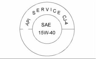
![]()
![]()

70
SEBU8605-01
Maintenance Section
Refill Capacities
• Perform maintenance at the intervals that are
specified in the Operation and Maintenance
Manual, “Maintenance Interval Schedule”.
Oil analysis
Some engines may be equipped with an oil sampling
valve. If oil analysis is required, the oil sampling valve
is used to obtain samples of the engine oil. The oil
analysis will complement the preventive maintenance
program.
The oil analysis is a diagnostic tool that is used to
determine oil performance and component wear
rates. Contamination can be identified and measured
by using oil analysis. The oil analysis includes the
following tests:
• The Wear Rate Analysis monitors the wear of the
engines metals. The amount of wear metal and
type of wear metal that is in the oil is analyzed. The
increase in the rate of engine wear metal in the
oil is as important as the quantity of engine wear
metal in the oil.
g02210556
Illustration 43
Lubricant Viscosities
Supplemental heat is recommended for cold soaked starts below
the minimum ambient temperature. Supplemental heat may be
required for cold soaked starts that are above the minimum
temperature that is stated, depending on the parasitic load and
other factors. Cold soaked starts occur when the engine has not
been operated for a period of time. This interval will allow the oil to
become more viscous due to cooler ambient temperatures.
• Tests are conducted in order to detect
contamination of the oil by water, glycol, or fuel.
• The Oil Condition Analysis determines the loss of
the oils lubricating properties. An infrared analysis
is used to compare the properties of new oil to the
properties of the used oil sample. This analysis
allows technicians to determine the amount of
deterioration of the oil during use. This analysis
also allows technicians to verify the performance
of the oil according to the specification during the
entire oil change interval.
Aftermarket Oil Additives
Perkins does not recommend the use of aftermarket
additives in oil. It is not necessary to use aftermarket
additives in order to achieve the engines maximum
service life or rated performance. Fully formulated,
finished oils consist of base oils and of commercial
additive packages. These additive packages are
blended into the base oils at precise percentages in
order to help provide finished oils with performance
characteristics that meet industry standards.
i04224221
Fluid Recommendations
There are no industry standard tests that evaluate
the performance or the compatibility of aftermarket
additives in finished oil. Aftermarket additives may
not be compatible with the finished oils additive
package, which could lower the performance of the
finished oil. The aftermarket additive could fail to mix
with the finished oil. This failure could produce sludge
in the crankcase. Perkins discourages the use of
aftermarket additives in finished oils.
• Glossary
• ISO International Standards Organization
• ASTM American Society for Testing and Materials
• HFRR High Frequency Reciprocating Rig for
Lubricity testing of diesel fuels
To achieve the best performance from a Perkins
engine, conform to the following guidelines:
• FAME Fatty Acid Methyl Esters
• CFR Co-ordinating Fuel Research
• ULSD Ultra Low Sulfur Diesel
• RME Rape Methyl Ester
• See the appropriate “Lubricant Viscosities”. Refer
to the illustration 43 in order to find the correct oil
viscosity grade for your engine.
• At the specified interval, service the engine. Use
new oil and install a new oil filter.
This document is printed from SPI². Not for RESALE
![]()
![]()
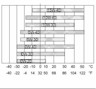
SEBU8605-01
71
Maintenance Section
Refill Capacities
• SME Soy Methyl Ester
• EPA Environmental Protection Agency of the
United States
• PPM Parts Per Million
• DPF Diesel Particulate Filter
General Information
NOTICE
Every attempt is made to provide accurate, up-to-date
information. By use of this document you agree that
Perkins Engines Company Limited is not responsible
for errors or omissions.
NOTICE
These recommendations are subject to change with-
out notice. Contact your local Perkins distributor for
the most up-to-date recommendations.
Diesel Fuel Requirements
Perkins is not in a position to continuously evaluate
and monitor all worldwide distillate diesel fuel
specifications that are published by governments and
technological societies.
The Perkins Specification for Distillate Diesel Fuel
provides a known reliable baseline in order to judge
the expected performance of distillate diesel fuels
that are derived from conventional sources.
Satisfactory engine performance is dependent on the
use of a good quality fuel. The use of a good quality
fuel will give the following results: long engine life
and acceptable exhaust emissions levels. The fuel
must meet the minimum requirements that are stated
in the table 17.
NOTICE
The footnotes are of the key part Perkins Specifica-
tion for Distillate Diesel Fuel Table. Read ALL of the
footnotes.
Table 17
Perkins Specification for Distillate Diesel Fuel
(1)
Property
Aromatics
Ash
UNITS
Requirements
35% maximum
0.01% maximum
0.35% maximum
“ASTM”Test
D1319
“ISO”Test
%Volume
%Weight
%Weight
“ISO”3837
“ISO”6245
“ISO”4262
D482
Carbon Residue on
10% Bottoms
D524
-
Cetane Number
(2)
40 minimum
D613/D6890
“ISO”5165
(continued)
This document is printed from SPI². Not for RESALE
![]()
![]()
![]()
![]()
![]()
![]()
![]()
72
SEBU8605-01
Maintenance Section
Refill Capacities
(Table 17, contd)
Cloud Point
°C
-
The cloud point must
not exceed the lowest
expected ambient
temperature.
D2500
“ISO”3015
“ISO”2160
Copper Strip
Corrosion
No. 3 maximum
D130
Density at 15 °C
Kg / M
°C
3
801 minimum and 876
maximum
No equivalent test
D86
“ISO 3675 ”“ISO 12185”
“ISO”3405
(59 °F)
(3)
Distillation
10% at 282 °C
(539.6 °F) maximum
90% at 360 °C (680 °F)
maximum
Flash Point
°C
-
legal limit
D93
“ISO”2719
Thermal Stability
Minimum of 80%
reflectance after aging
for 180 minutes at
150 °C (302 °F)
D6468
No equivalent test
Pour Point
°C
6 °C (42.8 °F) minimum
below ambient
D97
“ISO”3016
temperature
Sulfur
(1)
%mass
0.0015
D5453/D26222
D445
“ISO 20846 ”“ISO 20884”
“ISO”3405
Kinematic Viscosity
(4)
“MM”
2
“/S (cSt)”
The viscosity of the
fuel that is delivered to
the fuel injection pump.
“1.4 minimum/4.5
maximum”
Water and sediment
Water
% weight
% weight
% weight
mg/100mL
0.1% maximum
0.1% maximum
0.05% maximum
D1796
D1744
D473
“ISO”3734
No equivalent test
“ISO”3735
Sediment
Gums and Resins
(5)
10 mg per 100 mL
maximum
D381
“ISO”6246
mm
Lubricity corrected
0.52 maximum
D6079
“ISO”12156-1
wear scar diameter at
60 °C (140 °F).
(6)
(1) This specification includes the requirements for Ultra Low Sulfur Diesel (ULSD). ULSD fuel will have ≤ 15 ppm (0.0015%) sulfur. Refer to
“ASTM D5453”, “ASTM D2622”, or “ISO 20846, ISO 20884” test methods.
(2) A fuel with a higher cetane number is recommended in order to operate at a higher altitude or in cold weather.
(3) “Via standards tables, the equivalent API gravity for the minimum density of 801 kg / m
3
(kilograms per cubic meter) is 45 and for the
maximum density of 876 kg / m is 30”.
3
(4) The values of the fuel viscosity are the values as the fuel is delivered to the fuel injection pumps. Fuel should also meet the minimum
viscosity requirement and the fuel should meet the maximum viscosity requirements at 40 °C (104 °F) of either the “ASTM D445” test
method or the “ISO 3104” test method. If a fuel with a low viscosity is used, cooling of the fuel may be required to maintain “1.4 cSt”or
greater viscosity at the fuel injection pump. Fuels with a high viscosity might require fuel heaters in order to lower the viscosity to “1.4
cSt” at the fuel injection pump.
(5) Follow the test conditions and procedures for gasoline (motor).
(6) The lubricity of a fuel is a concern with ultra low sulfur fuel. To determine the lubricity of the fuel, use the “ISO 12156-1 or ASTM D6079
High Frequency Reciprocating Rig (HFRR)” test. If the lubricity of a fuel does not meet the minimum requirements, consult your fuel
supplier. Do not treat the fuel without consulting the fuel supplier. Some additives are not compatible. These additives can cause
problems in the fuel system.
Engines that are manufactured by Perkins are
certified with the fuel that is prescribed by the United
States Environmental Protection Agency. Engines
that are manufactured by Perkins are certified
with the fuel that is prescribed by the European
Certification. Perkins does not certify diesel engines
on any other fuel.
Note: The owner and the operator of the engine has
the responsibility of using the fuel that is prescribed by
the EPA and other appropriate regulatory agencies.
This document is printed from SPI². Not for RESALE
![]()

SEBU8605-01
73
Maintenance Section
Refill Capacities
NOTICE
Operating with fuels that do not meet the Perkins rec-
ommendations can cause the following effects: Start-
ing difficulty, reduced fuel filter service life, poor com-
bustion, deposits in the fuel injectors, significantly re-
duce service life of the fuel system, deposits in the
combustion chamber, and reduced service life of the
engine.
NOTICE
The Perkins 1200 series of diesel engine must be op-
erated using Ultra Low Sulfur Diesel. The sulphur con-
tent of this fuel must be lower than 15 PPM. This fuel
complies with the emissions regulations that are pre-
scribed by the Environmental Protection Agency of the
United States.
g02157153
Illustration 44
Illustration 44 is a representation of the label that will
be installed next to the fuel filler cap on the fuel tank
of the application.
The fuel specifications that are listed in the table 18
are released as acceptable to use on all 1200 series
of engine.
Table 18
Acceptable Fuel Specification for the 1200 Series of Engines
(1)
Fuel Specification
EN590
Comments
European Automotive Diesel Fuel (DERV)
“ASDM D975 GRADE 1D S15”
“North American Light Distillate Diesel fuel with less than 15
PPM sulfur level”
“ASTM D975 GRADE 2D S15”
“JIS K2204”
“North American Middle Distillate general purpose Diesel fuel
with less than 15 PPM sulfur level”
“Japanese Diesel Fuel” Must meet the requirements that are
stated in the section “Lubricity”.
“BS 2869: 2010 CLASS A2 or EU equivalent ”
“EU Off Road Diesel fuel. Acceptable from 2011 MUST have
less than 10 PPM sulfur level”
(1) All the fuels must comply with the specification in the table for the Perkins Specification Distillate Diesel Fuel.
This document is printed from SPI². Not for RESALE
![]()
![]()
![]()
![]()
![]()
![]()
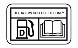
![]()

74
SEBU8605-01
Maintenance Section
Refill Capacities
Diesel Fuel Characteristics
Density
Cetane Number
Density is the mass of the fuel per unit volume
at a specific temperature. This parameter has a
direct influence on engine performance and a direct
influence on emissions. This influence determines
from a heat output given injected volume of fuel. This
3
parameter is quoted in the following kg/m at 15 °C
(59 °F).
Fuel that has a high cetane number will give a
shorter ignition delay. A high cetane number will
produce a better ignition quality. Cetane numbers are
derived for fuels against proportions of cetane and
heptamethylnonane in the standard CFR engine.
Refer to “ISO 5165” for the test method.
Perkins recommends a density of 841 kg/m in order
3
to obtain the correct power output. Lighter fuels are
acceptable but these fuels will not produce the rated
power.
Cetane numbers in excess of 45 are normally
expected from current diesel fuel. However, a cetane
number of 40 may be experienced in some territories.
The United States of America is one of the territories
that can have a low cetane value. A minimum cetane
value of 40 is required during average starting
conditions. A fuel with higher cetane number is
recommended for operations at high altitudes or in
cold-weather operations.
Sulfur
The level of sulfur is governed by emissions
legislations. Regional regulation, national regulations,
or international regulations can require a fuel with
a specific sulfur limit. The sulfur content of the fuel
and the fuel quality must comply with all existing local
regulations for emissions.
Fuel with a low cetane number can be the root cause
of problems during a cold start.
Viscosity
Perkins 1200 series diesel engines have been
designed to operate only with ULSD. By using the
test methods “ASTM D5453, ASTM D2622, or ISO
20846 ISO 20884”, the content of sulfur in ULSD fuel
must be below 15 PPM (mg/kg) or 0.0015% mass.
Viscosity is the property of a liquid of offering
resistance to shear or flow. Viscosity decreases
with increasing temperature. This decrease in
viscosity follows a logarithmic relationship for normal
fossil fuel. The common reference is to kinematic
viscosity. Kinematic viscosity is the quotient of the
dynamic viscosity that is divided by the density. The
determination of kinematic viscosity is normally by
readings from gravity flow viscometers at standard
temperatures. Refer to “ISO 3104” for the test
method.
NOTICE
Use of diesel fuel with higher than 15 PPM sulphur lim-
it in these engines will harm or permanently damage
emissions control systems and/or shorten their ser-
vice interval.
Lubricity
The viscosity of the fuel is significant because fuel
serves as a lubricant for the fuel system components.
Fuel must have sufficient viscosity in order to lubricate
the fuel system in both extremely cold temperatures
and extremely hot temperatures. If the kinematic
viscosity of the fuel is lower than “1.4 cSt” at the fuel
injection pump, damage to the fuel injection pump
can occur. This damage can be excessive scuffing
and seizure. Low viscosity may lead to difficult hot
restarting, stalling, and loss of performance. High
viscosity may result in seizure of the pump.
Lubricity is the capability of the fuel to prevent pump
wear. The fluids lubricity describes the ability of the
fluid to reduce the friction between surfaces that are
under load. This ability reduces the damage that is
caused by friction. Fuel injection systems rely on the
lubricating properties of the fuel. Until fuel sulfur limits
were mandated, the fuels lubricity was generally
believed to be a function of fuel viscosity.
The lubricity has particular significance to the current
ultra low sulfur fuel, and low aromatic fossil fuels.
These fuels are made in order to meet stringent
exhaust emissions.
Perkins recommends kinematic viscosities of 1.4 and
4.5 mm2/sec that is delivered to the fuel injection
pump. If a fuel with a low viscosity is used, cooling of
the fuel may be required to maintain 1.4 cSt or greater
viscosity at the fuel injection pump. Fuels with a high
viscosity might require fuel heaters in order to lower
the viscosity to 4.5 cSt at the fuel injection pump.
The lubricity of these fuels must not exceed wear scar
diameter of 0.52 mm (0.0205 inch). The fuel lubricity
test must be performed on an HFRR, operated at
60 °C (140 °F). Refer to “ISO 12156-1 ”.
This document is printed from SPI². Not for RESALE
![]()
![]()
![]()
SEBU8605-01
75
Maintenance Section
Refill Capacities
The U.S. distillate diesel fuel specification “ASTM
D975-09a” includes up to B5 (5 percent) biodiesel.
NOTICE
The fuels system has been qualified with fuel hav-
ing lubricity up to 0.52 mm (0.0205 inch) wear scar
diameter as tested by “ISO 12156-1”. Fuel with higher
wear scar diameter than 0.52 mm (0.0205 inch) will
lead to reduced service life and premature failure of
the fuel system.
European distillate diesel fuel specification EN590:
2010 includes up B7 (7 percent) biodiesel.
Note: Engines that are manufactured by Perkins
are certified by use of the prescribed Environmental
Protection Agency (EPA) and European Certification
fuels. Perkins does not certify engines on any other
fuel. The user of the engine has the responsibility
of using the correct fuel that is recommended by
the manufacturer and allowed by the EPA and other
appropriate regulatory agencies.
Fuel additives can enhance the lubricity of a fuel.
Contact your fuel supplier for those circumstances
when fuel additives are required. Your fuel supplier
can make recommendations for additives to use, and
for the proper level of treatment.
Specification Requirements
Distillation
The neat biodiesel must conform to the latest
“EN14214 or ASTM D6751” (in the USA). The
biodiesel can only be blended in mixture of up to
20% by volume in acceptable mineral diesel fuel
meeting latest edition of “EN590 or ASTM D975 S15”
designation.
Distillation is an indication of the mixture of different
hydrocarbons in the fuel. A high ratio of light weight
hydrocarbons can affect the characteristics of
combustion.
Recommendation for Biodiesel
In United States Biodiesel blends of B6 to B20 must
meet the requirements listed in the latest edition of
“ASTM D7467” (B6 to B20) and must be of an API
gravity of 30-45.
Biodiesel is a fuel that can be defined as mono-alkyl
esters of fatty acids. Biodiesel is a fuel that can be
made from various feedstock. The most commonly
available biodiesel in Europe is Rape Methyl Ester
(REM). This biodiesel is derived from rapeseed
oil. Soy Methyl Ester (SME) is the most common
biodiesel in the United States. This biodiesel is
derived from soybean oil. Soybean oil or rapeseed oil
are the primary feedstocks. These fuels are together
known as Fatty Acid Methyl Esters (FAME).
In North America biodiesel and biodiesel blends
must be purchased from the BQ-9000 accredited
producers and BQ-9000 certified distributors.
In other areas of the world, the use of biodiesel
that is BQ-9000 accredited and certified, or that is
accredited and certified by a comparable biodiesel
quality body to meet similar biodiesel quality
standards is required.
Raw pressed vegetable oils are NOT acceptable for
use as a fuel in any concentration in compression
engines. Without esterification, these oils solidify in
the crankcase and the fuel tank. These fuels may
not be compatible with many of the elastomers that
are used in engines that are manufactured today.
In original forms, these oils are not suitable for use
as a fuel in compression engines. Alternate base
stocks for biodiesel may include animal tallow, waste
cooking oils, or various other feedstocks. In order to
use any of the products that are listed as fuel, the oil
must be esterified.
Engine Service Requirements
Aggressive properties of biodiesel fuel may cause
debris in the fuel tank and fuel lines. The aggressive
properties of biodiesel will clean the fuel tank
and fuel lines. This cleaning of the fuel system
can prematurely block of the fuel filters. Perkins
recommend that after the initial usage of B20
biodiesel blended fuel the fuel filters must be replaced
at 50 hours.
Fuel made of 100 percent FAME is generally referred
to as B100 biodiesel or neat biodiesel.
Glycerides present in biodiesel fuel will also cause
fuel filters to become blocked more quickly. Therefore
the regular service interval should be reduced to 250
hours.
Biodiesel can be blended with distillate diesel fuel.
The blends can be used as fuel. The most commonly
available biodiesel blends are B5, which is 5 percent
biodiesel and 95 percent distillate diesel fuel. B20,
which is 20 percent biodiesel and 80 percent distillate
diesel fuel.
Note: The percentages given are volume-based.
This document is printed from SPI². Not for RESALE
![]()
![]()
![]()
76
SEBU8605-01
Maintenance Section
Refill Capacities
When biodiesel fuel is used, crank case oil and
aftertreatment systems may be influenced. This
influence is due to the chemical composition and
characteristics of biodiesel fuel, such as density and
volatility, and to chemical contaminants that can be
present in this fuel, such as alkali and alkaline metals
(sodium, potassium, calcium, and magnesium).
General Requirements
Biodiesel has poor oxidation stability, which can result
in long-term problems in the storage of biodiesel.
Biodiesel fuel should be used within 6 months of
manufacture. Equipment should not be stored with
the B20 biodiesel blends in the fuel system for longer
than 3 months.
• Crankcase oil fuel dilution can be higher when
biodiesel or biodiesel blends are used. This
increased level of fuel dilution when using biodiesel
or biodiesel blends is related to the typically lower
volatility of biodiesel. In-cylinder emissions control
strategies utilized in many of the industrial latest
engine designs may lead to a higher level of
biodiesel concentration in the sump. The long-term
effect of biodiesel concentration in crankcase oil is
currently unknown.
Due to poor oxidation stability and other potential
issues, it is strongly recommended that engines with
limited operational time either not use B20 biodiesel
blends or, while accepting some risk, limit biodiesel
blend to a maximum of B5. Examples of applications
that should limit the use of biodiesel are the following:
Standby Generator sets and certain emergency
vehicles.
Perkins strongly recommended that seasonally
operated engines have the fuel systems, including
fuel tanks, flashed with conventional diesel fuel
before prolonged shutdown periods. An example of
an application that should seasonally flush the fuel
system is a combine harvester.
• Perkins recommend the use of oil analysis in order
to check the quality of the engine oil if biodiesel
fuel is used. Ensure that the level of biodiesel in
the fuel is noted when the oil sample is taken.
Performance Related Issues
Microbial contamination and growth can cause
corrosion in the fuel system and premature plugging
of the fuel filter. Consult your supplier of fuel for
assistance in selecting appropriate anti-microbial
additive.
Due to the lower energy content than the standard
distillate fuel B20 will cause a power loss in order
of 2 to 4 percent. In addition, over time the power
may deteriorate further due to deposits in the fuel
injectors.
Water accelerates microbial contamination and
growth. When biodiesel is compared to distillate
fuels, water is naturally more likely to exist in the
biodiesel. It is therefore essential to check frequently
and if necessary, drain the water separator.
Biodiesel and biodiesel blends are known to cause
an increase in fuel system deposits, most significant
of which are deposits within the fuel injector. These
deposits can cause a loss in power due to restricted
or modified fuel injection or cause other functional
issues associated with these deposits.
Materials such as brass, bronze, copper, lead, tin,
and zinc accelerate the oxidation process of the
biodiesel fuel. The oxidation process can cause
deposits formation therefore these materials must not
be used for fuel tanks and fuel lines.
Note: Perkins T400012 Fuel Cleaner is most
effective in cleaning and preventing the formation
of deposits. Perkins Diesel Fuel Conditioner helps
to limit deposit issues by improving the stability of
biodiesel and biodiesel blends. For more information
refer to “Perkins Diesel Fuel System Cleaner”.
Fuel for Cold Weather Operation
The European standard “EN590” contains climate
dependant requirements and a range of options. The
options can be applied differently in each country.
There are five classes that are given to arctic climates
and severe winter climates. 0, 1, 2, 3, and 4.
Biodiesel fuel contains metal contaminants (sodium,
potassium, calcium, and/or magnesium) that form ash
products upon combustion in the diesel engine. The
ash can have an impact on the life and performance
of aftertreatment emissions control devices and can
accumulate in DPF. The ash accumulation may cause
the need for more frequent ash service intervals and
cause loss of performance
Fuel that complies with “EN590 ” CLASS 4 can be
used at temperatures as low as −44 °C (−47.2 °F).
Refer to “EN590” for a detailed discretion of the
physical properties of the fuel.
The diesel fuel “ASTM D975 1-D” used in the
United States of America may be used in very cold
temperatures that are below −18 °C (−0.4 °F).
This document is printed from SPI². Not for RESALE
![]()