 English
 Espaol
 Franais
 阿拉伯
阿拉伯 中文
中文 Deutsch
 Italiano
 Português
 日本
日本 韩国
韩国 български
 hrvatski
 esky
esky Dansk
Dansk Nederlands
 suomi
suomi Ελληνικ
 印度
印度 norsk
norsk Polski
 Roman
Roman русский
 Svenska
珀金斯Perkins1104C-E44(T)(TA)测试调整供应商,珀金斯Perkins1104C-E44(T)(TA)测试调整技术价格规格咨询服务,珀金斯Perkins1104C-E44(T)(TA)测试调整零配件供应,珀金斯Perkins1104C-E44(T)(TA)测试调整售后服务中心,珀金斯Perkins1104C-E44(T)(TA)测试调整,珀金斯Perkins1104C-E44(T)(TA)测试调整详细的技术参数,

产品中心
珀金斯Perkins1104C-E44(T)(TA)测试调整(英文)
详细描述
Systems Operation
Testing and Adjusting
1104E Engine
R F ( Engine)
RH (Engine)
R K ( Engine)
This document has been printed from SPI². Not for Resale
![]()
![]()
![]()
![]()
![]()
i01658146
ImportantSafetyInformation
Mostaccidentsthatinvolveproductoperation,maintenanceandrepairarecausedbyfailuretoobserve
basicsafetyrulesorprecautions.Anaccidentcanoftenbeavoidedbyrecognizingpotentiallyhazardous
situationsbeforeanaccidentoccurs.Apersonmustbealerttopotentialhazards.Thispersonshouldalso
havethenecessarytraining,skillsandtoolstoperformthesefunctionsproperly.
Improperoperation,lubrication,maintenanceorrepairofthisproductcanbedangerousand
couldresultininjuryordeath.
Donotoperateorperformanylubrication,maintenanceorrepaironthisproduct,untilyouhave
readandunderstoodtheoperation,lubrication,maintenanceandrepairinformation.
Safetyprecautionsandwarningsareprovidedinthismanualandontheproduct.Ifthesehazardwarnings
arenotheeded,bodilyinjuryordeathcouldoccurtoyouortootherpersons.
Thehazardsareidentifiedbythe“SafetyAlertSymbol”andfollowedbya“SignalWord”suchas
“DANGER”,“WARNING”or“CAUTION”.TheSafetyAlert“WARNING”labelisshownbelow.
Themeaningofthissafetyalertsymbolisasfollows:
Attention!BecomeAlert!YourSafetyisInvolved.
Themessagethatappearsunderthewarningexplainsthehazardandcanbeeitherwrittenorpictorially
presented.
Operationsthatmaycauseproductdamageareidentifiedby“NOTICE”labelsontheproductandin
thispublication.
Perkins cannot anticipa te e ver y p os sible c irc u mstance t hat m ight invol ve a pote n ti al hazard .
Thewarningsinthispublicationandontheproductare,therefore,notallinclusive.Ifatool,
proc edure, work me thod or ope rating technique tha t is not s pecific ally rec ommended by Perkins
isused,youmustsatisfyyourselfthatitissafeforyouandforothers.Youshouldalsoensurethat
theproductwillnotbedamagedorbemadeunsafebytheoperation,lubrication,maintenanceor
repairproceduresthatyouchoose.
Theinformation,specifications,andillustrationsinthispublicationareonthebasisofinformationthat
wasavailableatthetimethatthepublicationwaswritten.Thespecifications,torques,pressures,
measurements,adjustments,illustrations,andotheritemscanchangeatanytime.Thesechangescan
affecttheservicethatisgiventotheproduct.Obtainthecompleteandmostcurrentinformationbeforeyou
s t ar t any jo b . Perkins dea le rs hav e t he m os t c ur r en t i nfo rm ati on a va il abl e.
When replacement parts are required for this
product Perkinsre comme nds usi ng Perkins
re pl ace ment parts or parts w ith equiva lent
specificationsincluding,butnotlimitedto, phys-
icaldimensions,type,strengthandmaterial.
Failuretoheedthiswarningcanleadtoprema-
turefailures,productdamage,personalinjuryor
death.
This document has been printed from SPI². Not for Resale
![]()
![]()
![]()
SENR9977
3
Table of Contents
Table of Contents
Flywheel Housing - Inspect ................................... 54
Gear Group - Inspect ............................................ 55
Electrical System
Systems Operation Section
Alternator - Test .................................................... 56
Battery - Test ......................................................... 56
V-Belt - Test .......................................................... 57
Charging System - Test ........................................ 57
Electric Starting System - Test .............................. 58
Glow Plugs - Test .................................................. 60
General Information
Introduction ............................................................ 4
Engine Operation
Basic Engine ........................................................... 6
Air Inlet and Exhaust System ................................. 7
Cooling System .................................................... 10
Lubrication System ............................................... 11
Electrical System ................................................. 12
Fuel Injection ....................................................... 14
Electronic Control System ................................... 22
Power Sources ..................................................... 25
Glossary of Electronic Control Terms ................... 29
Index Section
Index ..................................................................... 61
Testing and Adjusting Section
Fuel System
Fuel System - Inspect ........................................... 32
Air in Fuel - Test .................................................... 32
Finding Top Center Position for No. 1 Piston ........ 33
Fuel Injection Timing - Adjust ................................ 34
Fuel Injection Timing - Check ............................... 35
Fuel Quality - Test ................................................. 35
Fuel System - Prime ............................................. 36
Fuel System Pressure - Test ................................. 36
Air Inlet and Exhaust System
Air Inlet and Exhaust System - Inspect ................. 38
Wastegate - Test ................................................... 38
Compression - Test ............................................... 39
Engine Valve Lash - Inspect/Adjust ...................... 39
Valve Depth - Inspect ............................................ 41
Valve Guide - Inspect ............................................ 41
Lubrication System
Engine Oil Pressure - Test .................................... 43
Engine Oil Pump - Inspect .................................... 43
Excessive Bearing Wear - Inspect ........................ 44
Excessive Engine Oil Consumption - Inspect ....... 44
Increased Engine Oil Temperature - Inspect ........ 45
Cooling System
Cooling System - Check (Overheating) ................ 46
Cooling System - Inspect ...................................... 47
Cooling System - Test ........................................... 47
Engine Oil Cooler - Inspect ................................... 49
Water Temperature Regulator - Test ..................... 49
Basic Engine
Piston Ring Groove - Inspect ................................ 50
Connecting Rod - Inspect ..................................... 50
Connecting Rod Bearings - Inspect ...................... 51
Main Bearings - Inspect ........................................ 51
Cylinder Block - Inspect ........................................ 51
Cylinder Head - Inspect ........................................ 52
Piston Height - Inspect .......................................... 52
Flywheel - Inspect ................................................. 53
This document has been printed from SPI². Not for Resale
![]()
4
SENR9977
Systems Operation Section
Systems Operation Section
General Information
i02245816
Introduction
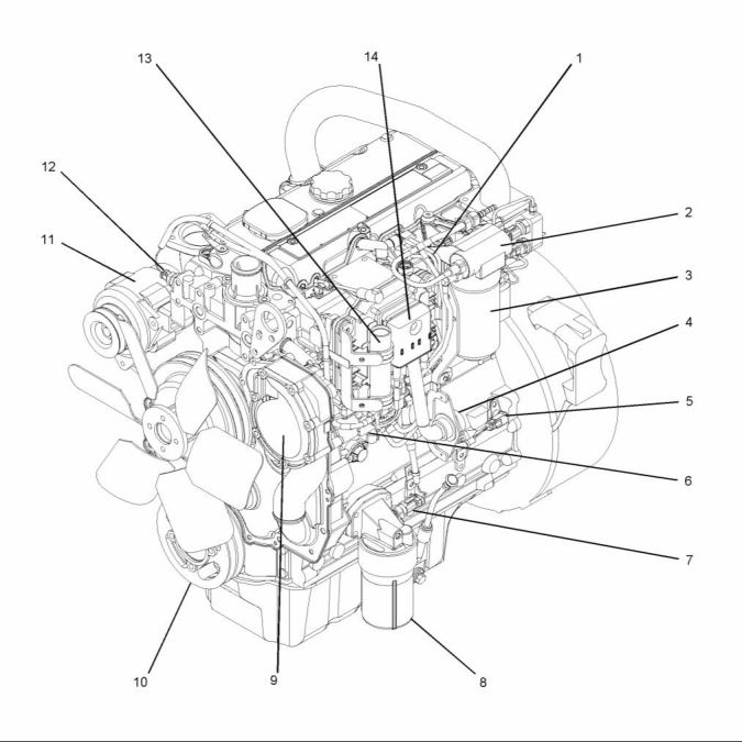
g01130896
Illustration 1
Left side view of a typical 1104C electronic engine
This document has been printed from SPI². Not for Resale
![]()
![]()
SENR9977
5
Systems Operation Section
(1) Fuel lines
(6) Electronic fuel injection pump
(7) Engine oil pressure sensor
(8) Engine oil filter
(11) Alternator
(12) Engine coolant temperature sensor
(13) Voltage Load Protection Module
(14) Electronic Control Module (ECM)
(2) Fuel Priming Pump
(3) Fuel Filter
(4) Machine Interface Connector (MIC)
(5) Speed/timing sensor
(9) Water Pump
(10) Crankshaft pulley
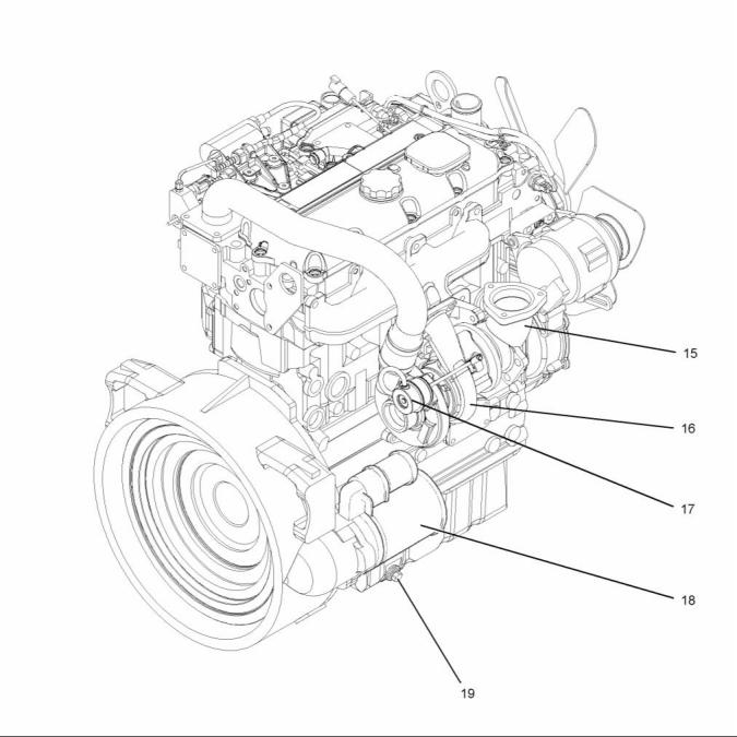
g01131299
Illustration 2
Right side view of a typical 1104C electronic engine
(15) Exhaust elbow
(16) Turbocharger
(17) Wastegate actuator
(18) Starter motor
(19) Oil drain plug
The 1104C electronic engine is electronically
controlled. The 1104C electronic engine uses an
Electronic Control Module (ECM) to control a fuel
injection pump. The pump supplies fuel to the fuel
injectors.
The four cylinders are arranged in-line. The cylinder
head assembly has one inlet valve and one exhaust
valve for each cylinder. The ports for the inlet valves
are on the left side of the cylinder head. The ports for
the exhaust valves are on the right side of the cylinder
head. Each cylinder valve has a single valve spring.
This document has been printed from SPI². Not for Resale
![]()
![]()
6
SENR9977
Systems Operation Section
Each cylinder has a piston cooling jet that is installed
in the cylinder block. The piston cooling jet sprays
engine oil onto the inner surface of the piston in
order to cool the piston. The pistons have a Fastram
combustion chamber in the top of the piston in order
to provide an efficient mix of fuel and air. The piston
pin is off-center in order to reduce the noise level.
The pistons have two compression rings and an
oil control ring. The groove for the top ring has a
hardened insert in order to reduce wear of the ring
groove. The skirt has a layer of graphite in order to
reduce wear. The correct piston height is important in
order to ensure that the piston does not contact the
cylinder head. The correct piston height also ensures
the efficient combustion of fuel which is necessary in
order to conform to requirements for emissions.
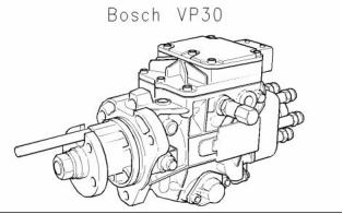
g00910750
Illustration 3
The Bosch VP30 fuel injection pump is installed on
the engine. The fuel injection pump conforms to
current emissions. Both the pump timing and the high
idle are preset at the factory. The fuel injection pump
is not serviceable. Adjustments to the fuel injection
pump timing and high idle should only be made by
personnel which have had the correct training. The
fuel injection pump uses the engine ECM to control
the engine RPM.
A piston and connecting rod are matched to each
cylinder. The piston height is controlled by the
length of the connecting rod. Six different lengths
of connecting rods are available in order to attain
the correct piston height. The different lengths of
connecting rods are made by machining the small
end bearing off-center in order to form an eccentric
bearing. The amount of the eccentricity of the bearing
creates the different lengths of the connecting rods.
The crankshaft has five main bearing journals. End
play is controlled by thrust washers which are located
on both sides of the center main bearing.
For the specifications of the 1104C electronic engine,
refer to the Specifications, “Engine Design”.
Engine Operation
The timing case is made of aluminum. The timing
gears have holes which align with holes in the front
flange of the crankshaft and the camshaft in order
to ensure the correct assembly of the gears. When
the number 1 piston is at the top center position
on the compression stroke, a temporary timing pin
is inserted through the crankshaft gear and the
hole in the front flange of the crankshaft. A second
temporary timing pin is inserted through the camshaft
gear and the hole in the timing case.
i02242513
Basic Engine
Cylinder Block and Cylinder Head
The crankshaft gear turns the idler gear which then
turns the following gears:
The cylinder block for the 1104 engine has four
cylinders which are arranged in-line.
• the camshaft gear
The cylinder block for the 1104 engine has five
main bearings which support the crankshaft. Thrust
washers on both sides of the center main bearing
control the end play of the crankshaft.
• the fuel injection pump
• a lower idler gear which turns the gear of the
lubricating oil pump
A cylinder head gasket is used between the
engine block and the cylinder head in order to seal
combustion gases, water, and oil.
The camshaft and the fuel injection pump run at half
the rpm of the crankshaft. The cylinder block has an
open top deck. The cylinders are only connected to
the cylinder block at the bottom.
This document has been printed from SPI². Not for Resale
![]()
![]()
SENR9977
7
Systems Operation Section
The engine has a cast iron cylinder head. The inlet
manifold is integral within the cylinder head. An inlet
valve and an exhaust valve for each cylinder are
controlled by a pushrod valve system. The ports for
the inlet valves are on the left side of the cylinder
head. The ports for the exhaust valves are on the
right side of the cylinder head.
• Fuel injection pump
• Lower idler gear which turns the gear of the
lubricating oil pump
Lip type seals are used on both the front of the
crankshaft and the rear of the crankshaft.
Pistons, Rings, and Connecting
Rods
Camshaft
The engine has a single camshaft. The camshaft
is driven by an idler gear in the front housing. The
camshaft uses only one bearing on the front journal.
The other journals rotate in the bore of the cylinder
block. The front bearing and the camshaft bores
in the cylinder block support the camshaft. As the
camshaft turns, the camshaft lobes move the valve
system components. The valve system components
move the inlet and exhaust valves in each cylinder.
The camshaft gear must be timed to the crankshaft
gear. The relationship between the lobes and the
camshaft gear causes the valves in each cylinder
to be opened and closed at the correct time. The
relationship between the lobes and the camshaft
gear also causes the valves in each cylinder to close
at the correct time.
The pistons have a combustion chamber in the top of
the piston in order to provide an efficient mix of fuel
and air. The piston pin is off-center in order to reduce
the noise level.
The pistons have two compression rings and an oil
control ring. The groove for the top ring has a hard
metal insert in order to reduce wear of the groove.
The skirt has a layer of graphite in order to reduce
wear.
The correct piston height is important in order to
ensure that the piston does not contact the cylinder
head. The correct piston height also ensures the
efficient combustion of fuel which is necessary in
order to conform to requirements for emissions.
i02242605
Air Inlet and Exhaust System
Engines are equipped with connecting rods that have
bearing caps that are fracture split. The bearing caps
on fracture split connecting rods are retained with
torx screws. Connecting rods with bearing caps that
are fracture split have the following characteristics:
• Higher integrity for the rod
• The splitting produces an accurately matched
surface on each side for improved strength.
• Modern design
The connecting rod is matched to each cylinder.
The piston height is controlled by the length of the
connecting rod. Six different lengths of connecting
rods are available in order to attain the correct piston
height. The different lengths of connecting rods are
made by machining the small end bearing off-center
in order to form an eccentric bearing. The amount of
the eccentricity of the bearing creates the different
lengths of the connecting rods.
g01130516
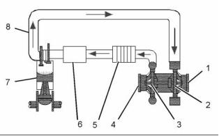
Illustration 4
Air inlet and exhaust system (typical example)
(1) Exhaust outlet
(2) Turbocharger turbine wheel
(3) Turbocharger compressor wheel
(4) Air intake
Crankshaft
(5) Aftercooler
(6) Intake manifold
The crankshaft changes the linear energy of the
pistons and connecting rods into rotary torque in
order to power external equipment.
(7) Engine cylinders
(8) Exhaust manifold
A gear at the front of the crankshaft drives the timing
gears. The crankshaft gear turns the idler gear which
then turns the following gears:
• Camshaft gear
This document has been printed from SPI². Not for Resale
![]()
![]()
8
SENR9977
Systems Operation Section
Engines which are naturally aspirated pull outside air
through an air cleaner directly into the inlet manifold
(6). The air flows from the intake manifold to the
engine cylinders (7). The fuel is mixed with the air in
the engine cylinders. After the fuel combustion occurs
in the engine cylinder, the exhaust gases flow directly
to the outside air through the exhaust manifold (8).
A turbocharger increases the temperature and the
density of the air that is sent to the engine cylinder.
This condition causes a lower temperature of ignition
to develop earlier in the compression stroke. The
compression stroke is also timed in a more accurate
way with the fuel injection. Surplus air lowers the
temperature of combustion. This surplus air also
provides internal cooling.
Turbocharged engines pull outside air through an air
cleaner into the air intake (4) of the turbocharger. The
suction is caused by the turbocharger compressor
wheel (3). Then, the turbocharger compressor
wheel compresses the air. The air flows through
the aftercooler (5). Cooling the inlet air increases
combustion efficiency. Increased combustion
efficiency helps achieve the following benefits:
A turbocharger improves the following aspects of
engine performance:
• Power output is increased.
• Fuel efficiency is improved.
• Engine torque is increased.
• Fuel consumption is reduced.
• Power output is increased.
• Durability of the engine is improved.
• Emissions from the engine are reduced.
• Emissions from the engine are reduced.
From the aftercooler (5), the air flows to the intake
manifold (6) which directs an even distribution of the
air to each engine cylinder (7). Air is pulled into the
engine cylinder (7) during the intake stroke of the
piston. Then, the air is mixed with fuel from the fuel
injectors.
Each piston makes four strokes:
1. Intake
2. Compression
3. Power
4. Exhaust
The sequence of the strokes by all of the pistons in
all of the engine cylinders provide constant air flow
through the inlet system during the engine operation.
g00302786
Illustration 5
The exhaust stroke and the timing of the valve
mechanism pushes combustion gases through the
open exhaust valve into the exhaust manifold (8).
The exhaust gases flow through the blades of the
turbocharger turbine wheel (2) which causes the
turbine wheel and the compressor wheel to turn.
Then, the exhaust gases flow through the exhaust
outlet (1) of the turbocharger to the outside.
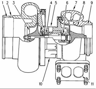
Components of a turbocharger (typical example)
(1) Air intake
(2) Compressor housing
(3) Compressor wheel
(4) Bearing
(5) Oil inlet port
(6) Bearing
(7) Turbine housing
(8) Turbine wheel
(9) Exhaust outlet
(10) Oil outlet port
(11) Exhaust inlet
The air inlet system is also equipped with a crankcase
ventilation system. The intake strokes of the pistons
pull in atmospheric air to the crankcase.
A turbocharger is installed between the exhaust
and intake manifolds. The turbocharger is driven by
exhaust gases which flow through the exhaust inlet
(11). The energy of the exhaust gas turns the turbine
wheel (8). Then, the exhaust gas flows out of the
turbine housing (7) through the exhaust outlet (9).
Turbocharger
Note: The turbocharger is not serviceable.
This document has been printed from SPI². Not for Resale
![]()
![]()
SENR9977
9
Systems Operation Section
The turbine wheel and the compressor wheel (3) are
installed on the same shaft. Therefore, the turbine
wheel and the compressor wheel rotate at the same
rpm. The compressor wheel is enclosed by the
compressor housing (2). The compressor wheel
compresses the intake air (1). The intake air flows
into the engine cylinders through the inlet valves of
the cylinders.
• Rocker arms
• Valve springs
The camshaft gear is driven by the crankshaft gear.
The camshaft and the crankshaft are timed together.
When the camshaft turns, the valve lifters and the
pushrods are moved up and down. The pushrods
move the rocker arms. The movement of the rocker
arms open the valves. The opening and closing of
the valves is timed with the firing sequence of the
engine. The valve springs push the valves back to
the closed position.
The oil from the main gallery of the cylinder block
flows through the oil inlet port (5) in order to
lubricate the turbocharger bearings (4) and (6). The
pressurized oil passes through the bearing housing
of the turbocharger. The oil is returned through the oil
outlet port (10) to the oil pan.
The turbocharger has a wastegate. The wastegate is
controlled by the boost pressure. This allows some
of the exhaust to bypass the turbocharger at higher
engine speeds. The wastegate is a type of valve
that automatically opens at a preset level of boost
pressure in order to allow exhaust gas to flow around
the turbine. The wastegate allows the design of the
turbocharger to be more effective at lower engine
speeds.
The wastegate is controlled by a diaphragm. One
side of this diaphragm is open to the atmosphere.
The other side of this diaphragm is open to the
manifold pressure.
Cylinder Head And Valves
The valves and the valve mechanism control the
flow of the air and the exhaust gases in the cylinder
during engine operation. The cylinder head assembly
has two valves for each cylinder. Each valve has one
valve spring. The ports for the inlet valves are on
the left side of the cylinder head. The ports for the
exhaust valves are on the right side of the cylinder
head. Steel valve seat inserts are installed in the
cylinder head for both the inlet and the exhaust
valves. The valve seat inserts can be replaced.
The valves are installed in valve guides. The valve
guides can be replaced. The exhaust valve guide has
a counterbore in order to prevent the seizure of the
valve stem. The seizure of the valve stem is caused
by a buildup of carbon under the head of the valve.
The inlet and the exhaust valves are opened and
closed by the rotation and movement of the following
components:
• Crankshaft
• Camshaft
• Valve lifters
• Pushrods
This document has been printed from SPI². Not for Resale
![]()
10
SENR9977
Systems Operation Section
i02242619
Cooling System
g00985481
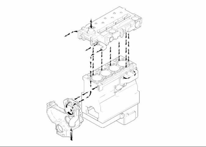
Illustration 6
Flow diagram of the cooling system
The coolant flows from the bottom of the radiator to
the centrifugal water pump. The water pump assists
in the flow of the coolant through the system. The
water pump is installed on the front of the timing
case. The water pump is gear-driven by the fuel
injection pump gear.
The main flow of the coolant passes from the rear of
the cylinder block into the rear of the cylinder head.
The coolant flows forward through the cylinder head
and into the water temperature regulator housing. If
the water temperature regulator is closed, the coolant
goes directly through a bypass to the inlet side of
the water pump. If the water temperature regulator
is open, the bypass is closed and the coolant flows
to the top of the radiator.
The water pump forces the coolant through a
passage in the front of the timing case to the water
jacket in the top left side of the cylinder block. The
coolant continues to the rear of the cylinder block.
From the rear of the cylinder block, some of the
coolant passes into the oil cooler. The oil cooler is
located on the left side of the cylinder block with no
external lines. The coolant flows around the element
of the oil cooler before being returned to the rear of
the cylinder block.
This document has been printed from SPI². Not for Resale
![]()
![]()
SENR9977
11
Systems Operation Section
i02242521
Lubrication System
g01009682
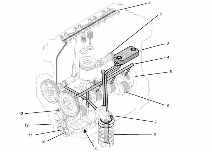
Illustration 7
Flow diagram of the lubrication system
Lubricating oil from the oil pan flows through a
strainer and a pipe (9) to the suction side of the
engine oil pump (10). Pressure for the lubrication
system is supplied by the oil pump. The crankshaft
gear (13) drives a lower idler gear (12). The lower
idler gear drives the oil pump gear (11). The pump
has an inner rotor and an outer rotor. The axis of
rotation of the rotors are off-center relative to each
other. There is an interference fit between the inner
rotor and the drive shaft.
The lubricating oil flows from the outlet side of the oil
pump (10) through a passage to the oil filter head
(7). The oil then flows from the oil filter head through
a passage to a plate type oil cooler. The oil cooler is
located on the left side of the cylinder block.
From the oil cooler, the oil returns through a passage
to the oil filter head. The oil then flows through a
bypass valve that permits the lubrication system
to function if the oil filter becomes blocked. Under
normal conditions, the oil then flows to the oil filter (8).
The inner rotor has five lobes which mesh with the six
lobes of the outer rotor. When the pump rotates, the
distance increases between the lobes of the outer
rotor and the lobes of the inner rotor in order to create
suction. When the distance decreases between the
lobes, pressure is created.
The oil flows from the oil filter through a passage that
is drilled across the cylinder block to the oil gallery
(4). The oil gallery is drilled through the total length
of the left side of the cylinder block. If the oil filter is
on the right side of the engine, the oil flows through
a passage that is drilled across the cylinder block to
the pressure gallery.
This document has been printed from SPI². Not for Resale
![]()
![]()
12
SENR9977
Systems Operation Section
Lubricating oil from the oil gallery flows through
high pressure passages to the main bearings of
the crankshaft (5). Then, the oil flows through the
passages in the crankshaft to the connecting rod
bearing journals (6). The pistons and the cylinder
bores are lubricated by the splash of oil and the oil
mist.
Alternator
Lubricating oil from the main bearings flows through
passages in the cylinder block to the journals of the
camshaft. Then, the oil flows from the front journal
of the camshaft (2) at a reduced pressure to the
cylinder head. The oil then flows through the center
of the rocker shaft (1) to the rocker arm levers. The
valve stems, the valve springs and the valve lifters
are lubricated by the splash and the oil mist.
The hub of the idler gear is lubricated by oil from the
oil gallery. The timing gears are lubricated by the
splash from the oil.
An external line from the cylinder block supplies oil to
the turbocharger. The oil then flows through a return
line to the oil pan.
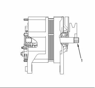
g00303424
Illustration 8
(1) Shaft for mounting the pulley
Engines have piston cooling jets that are supplied
with oil from the oil gallery. The piston cooling jets
spray lubricating oil on the underside of the pistons in
order to cool the pistons.
The alternator produces the following electrical
output:
• Three-phase
• Full-wave
• Rectified
i02242636
Electrical System
The alternator is an electro-mechanical component.
The alternator is driven by a drive belt from the
crankshaft pulley. The alternator charges the storage
battery during the engine operation.
The electrical system is a negative ground system.
The charging circuit operates when the engine
is running. The alternator in the charging circuit
produces direct current for the electrical system.
The alternator converts the mechanical energy
and the magnetic energy into electrical energy.
This conversion is done by rotating a direct current
electromagnetic field on the inside of a three-phase
stator. The electromagnetic field is generated by
electrical current flowing through a rotor. The stator
generates AC electrical power.
The alternating current is changed to direct current
by a three-phase, full-wave rectifier. Direct current
flows to the output terminal of the alternator. The
rectifier has three exciter diodes. The direct current
is used for the charging process.
A regulator is installed on the rear end of the
alternator. Two brushes conduct current through two
slip rings. The current then flows to the rotor field. A
capacitor protects the rectifier from high voltages.
This document has been printed from SPI². Not for Resale
![]()
![]()
SENR9977
13
Systems Operation Section
The alternator is connected to the battery through
the ignition switch. Therefore, alternator excitation
occurs when the switch is in the ON position.
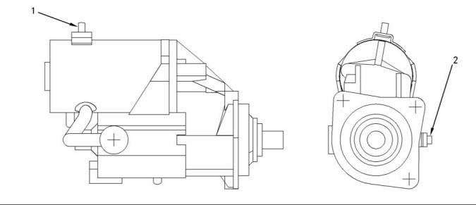
Starting Motor
g00956095
Illustration 9
24 Volt Starting Motor
(1) Terminal for connection of the ignition
switch
(2) Terminal for connection of the battery
cable
The starting motor has a solenoid. When the ignition
switch is activated, voltage from the electrical system
will cause the solenoid to engage the pinion in the
flywheel ring gear of the engine. When the pinion
gear is engaged in the flywheel ring gear, the
electrical contacts in the solenoid close the circuit
between the battery and the starting motor. This
causes the starting motor to rotate. This type of
activation is called a positive shift.
When the engine begins to run, the overrunning
clutch of the pinion drive prevents damage to the
armature. Damage to the armature is caused by
excessive speeds. The clutch prevents damage by
stopping the mechanical connection. However, the
pinion will stay meshed with the ring gear until the
ignition switch is released. A spring in the overrunning
clutch returns the clutch to the rest position.
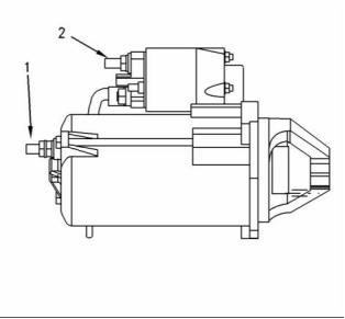
g00954820
Illustration 10
12 Volt Starting Motor
(1) Terminal for connection of the battery cable
(2) Terminal for connection of the ignition switch
The starting motor turns the engine flywheel. The
rpm is high enough in order to initiate a sustained
operation of the fuel ignition in the cylinders.
This document has been printed from SPI². Not for Resale
![]()
![]()
![]()
14
SENR9977
Systems Operation Section
i02247913
Fuel Injection
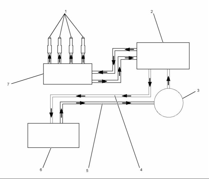
g01131813
Illustration 11
Flow diagram of the fuel system
(1) Fuel injectors
(4) Fuel return lines
(5) Fuel lines
(2) Fuel transfer pump and secondary fuel
filter
(6) Fuel tank
(3) Primary fuel filter and water separator
(7) Fuel injection pump
The 1104C electronic engine is equipped with a
Bosch VP30 fuel injection pump. The fuel injection
pump is an axial piston distributor injection pump that
is controlled by the Electronic Control Module (ECM).
The axial piston distributor injection pump generates
injection pressure for all cylinders in a single pump.
The fuel injection pump is responsible for the
distribution of fuel to the fuel injectors. The injection
pressure is generated by an axially moving piston.
The movement of the piston is parallel to the fuel
injection pump shaft.
This document has been printed from SPI². Not for Resale
![]()
![]()
SENR9977
15
Systems Operation Section
When the engine is operated, the fuel is pulled from
the fuel tank (6) through the primary fuel filter/water
separator (3) by the fuel transfer pump (2). When the
fuel passes through the water separator, any water
in the fuel will go to the bottom of the bowl. The fuel
transfer pump is equipped with a secondary fuel filter.
From the fuel priming pump, the fuel passes through
the fuel supply line to the fuel injection pump (7).
The fuel injection pump sends fuel through the high
pressure fuel lines to the fuel injectors (1). The fuel
injectors spray atomized fuel into the cylinders.
The fuel injection pump needs fuel for lubrication. The
precision parts of the pump are easily damaged. The
engine must not be operated until the fuel injection
pump is full of fuel. The system must be primed when
any part of the system is drained of fuel. The fuel
system needs priming when a fuel filter is changed,
and/or when a fuel line is removed, and/or when the
fuel injection pump is replaced.
This document has been printed from SPI². Not for Resale
![]()
16
SENR9977
Systems Operation Section
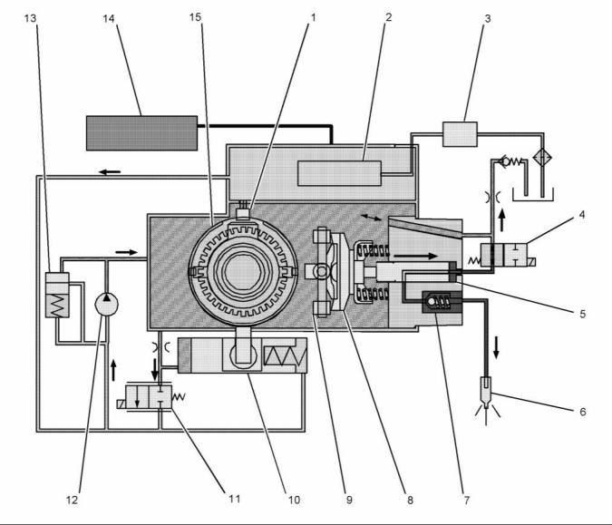
Fuel Injection Pump
g01132091
Illustration 12
Schematic of the Bosch VP30 fuel injection pump
(1) Speed/timing sensor
(2) Electronic control unit (ECU) for the fuel
injection pump
(8) Cam plate
(9) Roller
(10) Timing advance mechanism
(11) Timing solenoid valve
(12) Fuel transfer pump
(13) Pressure regulator
(14) ECM
(3) Fuel transfer pump
(4) Fuel solenoid valve
(5) Distributor plunger
(6) Fuel injector
(7) Delivery valve
(15) Cam ring
The fuel injection pump has the following operations:
• Delivery
• Shutoff
• Control
• Generation of high pressure
• Distribution and injection
• Timing and control
This document has been printed from SPI². Not for Resale
![]()
![]()
SENR9977
17
Systems Operation Section
Delivery
The eccentric position of the rotor is relative to the
cam ring. A volume is created between the vanes,
the rotor, and the cam ring. The fuel is transported
by the eccentric position. The eccentric position is
relative to the rotor and the outlet passage (19).
The fuel is transferred to the outlet passage into the
distributor plunger. The volume of the fuel is reduced
between the inlet passage and the outlet passage.
This creates pressure before the delivery to the
distributor plunger.
The quantity of fuel increases as the speed of the
engine increases. Increased engine speed increases
the delivery pressure of the fuel. The pressure inside
the pump is limited by a pressure regulator. The
pressure regulator controls the fuel pressure. The
fuel forces the valve spring open and the fuel flows
back into the inlet passage from the inside of the fuel
injection pump.
g01132094
Illustration 13
Center view of the Bosch VP30 fuel injection pump
(16) Fuel transfer pump
Generation of High Pressure
Fuel is supplied by the head pressure of the priming
pump. The fuel enters the fuel transfer pump (16) of
the fuel injection pump. The fuel transfer pump is a
vane pump. The transfer pump is driven by the fuel
injection pump shaft. The pump supplies a constant
amount of fuel to the interior of the fuel injection
pump. The revolution of the transfer pump is directly
related to the speed of the fuel injection pump shaft.
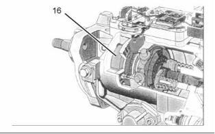
g01132111
Illustration 15
The distributor rotor and the cam plate of the Bosch VP30 fuel
injection pump
(23) Cam ring
(24) Cam plate
(25) Roller
(26) Head of the distributor
(27) Distributor plunger
(28) Springs
The fuel comes from the outlet passage of the fuel
transfer pump. The high pressure is generated
by the axial movement of the distributor plunger.
The cam plate is driven by the fuel injection pump
shaft. The cam plate has four cams. The number of
cams corresponds to the number of cylinders of the
engine. The cams on the cam plate run on the rollers.
The rollers are fixed on the cam ring. The rotating
movement and the lifting movement of the cam plate
makes the generation of high pressure.
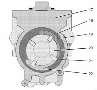
g01132095
Illustration 14
Fuel transfer pump for the Bosch VP30 fuel injection pump
(17) Pump housing
(18) Cam ring
(19) Outlet passage
(20) Rotor
(21) Vane
(22) Inlet passage
The rotor (20) rotates inside the cam ring (18). The
ring is firmly attached to the pump housing (17). The
vanes (21) are pressed against the ring by centrifugal
force. The fuel flows through the inlet passage (22)
then into a recess in the pump housing.
This document has been printed from SPI². Not for Resale
![]()
![]()
![]()
![]()
18
SENR9977
Systems Operation Section
The cam plate moves the distributor plunger toward
the head of the distributor (26). The high pressure is
created by a decrease in the volume between the
distributor plunger and the head of the distributor.
The cam plate is pressed to the ring by two springs
(28). This brings the distributor plunger back to the
original position. The fuel solenoid valve closes the
high pressure volume.
Distribution and Injection
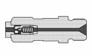
g01132170
Illustration 18
Delivery valve in the closed position
The delivery valve ensures that the pressure waves
do not allow a reopening of the injector . The pressure
waves are created at the end of the injection process.
The valve cone is lifted by the fuel pressure.
The fuel is forced through the fuel line to the injector.
The delivery ends and the fuel pressure drops. The
valve spring presses the valve cone onto the valve
seat. The reopening of a fuel injector has a negative
effect on emissions.
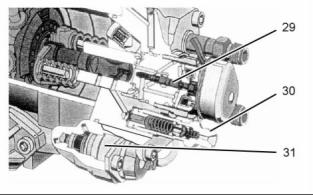
g01132136
Illustration 16
The rear view of the Bosch VP30 fuel injection pump
(29) Fuel solenoid valve
(30) Delivery valve
Timing
(31) Timing solenoid valve
The distribution of fuel to the injectors takes place
through the rotating movement of the distributor
plunger. The fuel solenoid valve meters the amount
of fuel by the following operations:
Retarding of the fuel injection is the direct relationship
between the start of injection and the position of the
piston. The timing compensates for the higher RPM
of the engine by advancing the start of injection.
• Time of closure
• Duration time
• Start of injection
• Amount of fuel
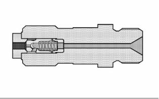
g01132164
Illustration 17
Delivery of fuel from the open delivery valve
This document has been printed from SPI². Not for Resale
![]()
![]()
![]()
![]()
![]()
SENR9977
19
Systems Operation Section
1. The ECU sends a signal to the timing solenoid
valve.
2. The timing mechanism is triggered by the timing
solenoid valve.
3. The timing solenoid valve changes the pressure in
the timing mechanism.
4. The timing mechanism changes the position of
the cam ring.
5. The cam ring changes the position of the rollers.
6. The rollers change the position of the cam plate.
7. The cam plate changes the timing of the fuel
delivery.
Control
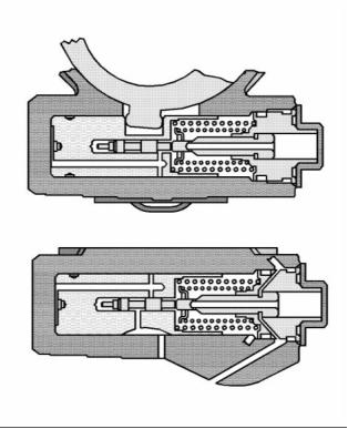
g01133210
Illustration 19
Timing advance for timing mechanism (side view and top view)
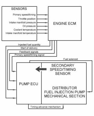
g01143278
Illustration 21
Electronic control for the fuel system (typical example)
The ECU for the injection pump uses the command
from the ECM and the measured values from the
speed/timing sensor to actuate the fuel solenoid
valve.
g01133211
Illustration 20
Timing retard for timing mechanism (side view and top view)
The timing advance or the timing retard of the fuel
injection pump is shown in the following steps:
This document has been printed from SPI². Not for Resale
![]()
![]()
![]()

![]()
![]()
20
SENR9977
Systems Operation Section
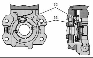
g01133212
Illustration 22
The timing wheel and the secondary speed/timing sensor
(32) Secondary speed/timing sensor
(33) Timing wheel
The ECU for the fuel injection pump is mounted on
the top of the pump. The ECU has a connection
to the engine ECM and a connection to the
speed/timing sensor. The ECU has a connection for
the two solenoid valves. The ECM functions as a
control computer. The ECU calculates the optimal
parameters from the ECM data. The fuel solenoid
actuates the valve accordingly.
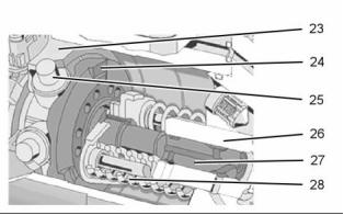
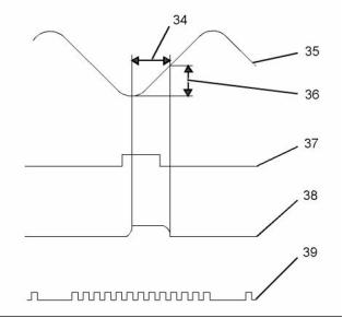
g01133213
Illustration 23
Operating principle
(34) Angle of fuel delivery
(35) Lift of the cam
(36) Stroke
(37) Pulse for actuating the fuel solenoid
(38) Valve lift
(39) Angle of the speed/timing sensor
The secondary speed/timing sensor in the fuel
injection pump determines the precise angular
position and the speed of the fuel injection pump
shaft. The timing wheel (23) is permanently
connected to the fuel injection pump shaft. The
secondary speed/timing sensor gets information from
the timing wheel. The sensor then sends electrical
impulses to the ECU. The ECU also uses the
information to determine the average speed of the
pump and momentary speed of the pump.
The amount of fuel is proportional to the stroke of
the piston. The effective stroke is proportional to the
angle of fuel delivery. A temperature compensation
takes place in the ECU. The compensation takes
place in order to inject the precise amount of fuel.
Shutoff
The engine shuts off by interrupting the fuel supply.
The engine Electronic Control Module (ECM)
specifies the amount of fuel. The fuel solenoid valve
is switched by the ECU on the fuel injection pump
to the zero fuel position.
Note: The engine will not run if the secondary
speed/timing sensor fails.
The signal of the speed/timing sensor is constant.
Power command signals are routed over the CAN
data link from the engine ECM to the ECU on the fuel
injection pump.
This document has been printed from SPI². Not for Resale
![]()
![]()
![]()
SENR9977
21
Systems Operation Section
Fuel Injectors
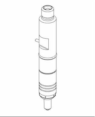
g01142467
Illustration 24
Each fuel injector is held into the cylinder head by a
clamp around the fuel injector. The fuel injectors are
not serviceable but the nozzles can be removed in
order to clean the orifice.
The fuel injection pump forces the fuel to flow under
high pressure to the hole in the fuel inlet. The fuel
then flows around a needle valve within the nozzle
holder which causes the nozzle to fill with fuel. The
pressure of the fuel pushes the needle valve and a
spring. When the force of the fuel pressure is greater
than the force of the spring, the needle valve will lift
up.
When the needle valve opens, fuel under high
pressure will flow through the nozzle orifices into the
cylinder. The fuel is injected into the cylinder through
the orifices in the nozzle end as a very fine spray.
When the fuel is injected into the cylinder, the force
of the fuel pressure in the nozzle body will decrease.
The force of the spring will then be greater than the
force of the fuel pressure that is in the nozzle body.
The needle valve will move quickly to the closed
position.
The needle valve has a close fit with the inside of the
nozzle. This makes a positive seal for the valve.
This document has been printed from SPI². Not for Resale
![]()
![]()
22
SENR9977
Systems Operation Section
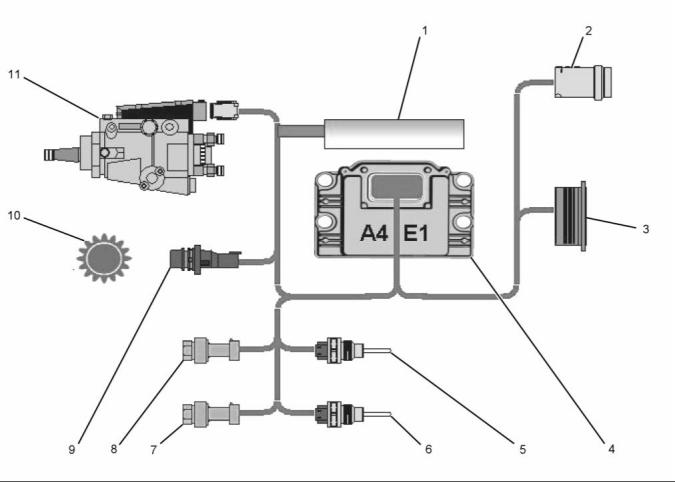
i02251280
Electronic Control System
g01133227
Illustration 25
Schematic of the electronic control system
(1) Voltage load-dump protection module
(VLPM)
(4) ECM
(8) Intake manifold pressure sensor
(9) Primary speed/timing sensor
(10) Timing wheel
(5) Coolant temperature sensor
(6) Intake manifold temperature sensor
(7) Engine oil pressure sensor
(2) Service tool connector
(3) Machine interface connector
(11) Fuel injection pump
The electronic control system for the 1104C electronic
engine has the following components:
• Electronic control module (ECM)
• Pressure sensors
• Temperature Sensors
• Primary speed/timing sensor
• Voltage load-dump protection module (VLPM)
This document has been printed from SPI². Not for Resale
![]()
![]()
SENR9977
23
Systems Operation Section
Electronic Control Module (ECM)
Flash programming is the method of programming
or updating the personality module. Refer to
Troubleshooting, RENR2696, “Flash Programming ”
for the instructions on the flash programming of the
personality module.
The ECM is sealed and the ECM needs no routine
adjustment or maintenance.
Pressure Sensors
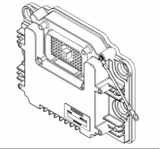
g01133234
Illustration 26
Electronic control module (ECM)
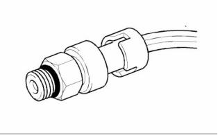
g00884730
Illustration 27
Intake manifold pressure sensor
The ECM functions as the governor and the computer
for the fuel system. The ECM receives all the signals
from the sensors in order to control the timing and
the engine speed.
The intake manifold pressure sensor is a three-wire
active sensor that is supplied with power from
the ECM. The sensor provides the ECM with a
measurement of intake manifold pressure in order
to control the air/fuel ratio. This will reduce the
engine smoke during transient conditions. The intake
manifold pressure sensor is also used for engine
monitoring.
Reprogramming of the ECM requires factory
passwords. The reasons for having passwords in an
ECM are the following reasons:
• Prevent unauthorized reprogramming.
• Prevent unauthorized erasing of logged events.
The operating range for the intake manifold pressure
sensor ................ 55 kPa to 339 kPa (8 psi to 50 psi)
• Allow the customer to control certain programmable
engine parameters.
Required accuracy ......... ±3% of maximum pressure
The factory passwords restrict changes to authorized
personnel. Factory passwords are required to
clear any event code. Refer to Troubleshooting,
RENR2696, “Factory Passwords” for more
information on the passwords.
The ECM has an excellent record of reliability. Any
problems in the system are most likely to be the
connectors and the wiring harness. The ECM should
be the last item in troubleshooting the engine.
The personality module contains the software with
all the fuel setting information. The information
determines the engine performance. The personality
module is installed behind the access panel on the
ECM.
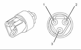
g01133306
Illustration 28
Engine oil pressure sensor
(1) Sensor common
(2) 5 volt supply
(3) Pressure signal
This document has been printed from SPI². Not for Resale
![]()
![]()
![]()
![]()
24
SENR9977
Systems Operation Section
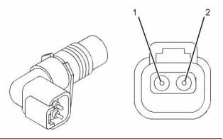
Primary Speed/Timing Sensor
The engine oil pressure sensor is also an active
sensor with three wires and a power supply. The
sensor provides the ECM with a measurement of
engine oil pressure. The ECM can warn the operator
of possible conditions that can damage the engine.
This includes the detection of a blocked oil filter.
The operating range for the engine oil pressure
sensor ....................... 110 to 882 kPa (16 to 128 psi)
Required accuracy ......... ±3% of maximum pressure
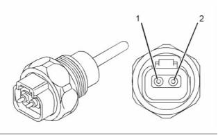
Temperature Sensors
g01133334
Illustration 30
Primary speed/timing sensor
(1) Negative terminal
(2) Positive terminal
The primary speed/timing sensor is also a two-wire
passive sensor. The sensor provides the ECM with
the speed and the position of the engine from a timing
wheel that is mounted on the crankshaft so that
the ECM can request fuel and timing from the fuel
injection pump. The timing wheel has one missing
tooth that is located 70 degrees after top center.
g01133312
Illustration 29
Temperature sensor
(1) Negative terminal
(2) Positive terminal
The operating range for the primary speed/timing
sensor ........................................... 142 to 3333 RPM
When the engine is cranking, the ECM uses the
signal from the secondary speed/timing sensor in the
fuel injection pump. When the engine is running, the
ECM uses the signal from the primary speed/timing
sensor on the crankshaft. This speed/timing sensor
is the primary source of the engine position.
The intake manifold temperature sensor and
the coolant temperature sensor are two-wire
passive sensors. The intake manifold temperature
sensor provides the ECM with intake manifold air
temperature so that the ECM can control the fuel for
starting and injection timing. The coolant temperature
sensor provides the ECM with coolant temperature
so that the ECM can control injection timing. The
temperature sensors are also used for engine
monitoring.
Note: If the primary speed/timing sensor fails, the
engine will be derated and the engine will continue to
operate on the secondary speed/timing sensor. Refer
to Troubleshooting, RENR2696 for more information.
The operating range for the temperature
sensors ..................... −40° to 150°C (−40° to 302°F)
Required accuracy for sensor ........... ±1 °C (±1.8 °F)
This document has been printed from SPI². Not for Resale
![]()
![]()
![]()
SENR9977
25
Systems Operation Section
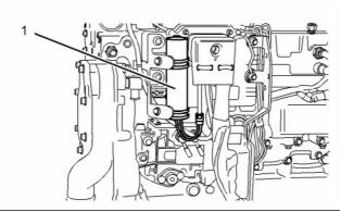
Voltage Load-dump Protection
Module (VLPM)
g01133354
Illustration 31
(1) VLPM
The VLPM monitors the voltage of the system and
the VLPM will protect the ECU on the fuel injection
pump against voltage spikes and reverse polarity.
The fuel injection pump will be shutdown if there is
high voltage on the system.
i02251435
Power Sources
Introduction (Power Supplies)
The 1104C electronic engine has four supplies to the
following components:
• ECM
• Fuel Injection Pump
• Pressure sensors
• Throttle position sensor
This document has been printed from SPI². Not for Resale
![]()
![]()
26
SENR9977
Systems Operation Section
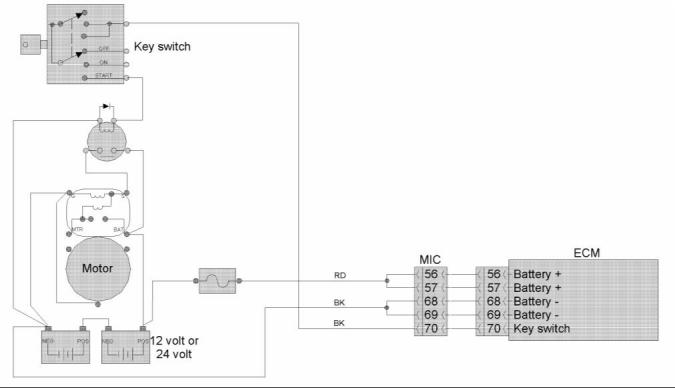
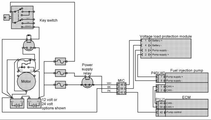
ECM Power Supply
g01141374
Illustration 32
Power Supply for the ECM
The power supply to the ECM and the system
is drawn from the 24 volt or the 12 volt battery.
The power supply for the ECM has the following
components:
The display screen on the electronic service tool can
be used in order to check the voltage supply.
Note: Two wires are used to reduce resistance.
• Battery
• disconnect switch
• Key start switch
• Fuses
• Ground bolt
• ECM connector
• Machine interface connector
Note: The ground bolt is the only component that is
mounted on the engine.
The Schematic for the ECM shows the main
components for a typical power supply circuit. Battery
voltage is normally connected to the ECM. The input
from the key start switch turns on the ECM.
The wiring harness can be bypassed for
troubleshooting purposes.
This document has been printed from SPI². Not for Resale
![]()
![]()
SENR9977
27
Systems Operation Section
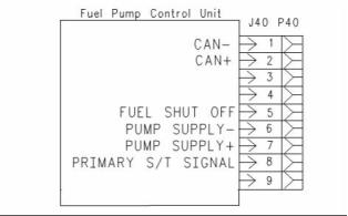
Power Supply for the Fuel Injection
Pump
g01141661
Illustration 33
Power supply for the fuel injection pump
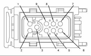
g00931447
g01143327
Illustration 34
Illustration 35
Connection for the fuel injection pump (J40/P40)
Connector for the fuel injection pump (J40)
(1) Can -
(2) Can +
(3) Unused
(4) Unused
(5) Fuel shutoff
(6) Battery -
(7) Battery +
(8) Signal for primary speed/timing sensor
(9) Unused
The power supply for the ECM comes from the
machine interface connector. The machine interface
connector receives power from the power relay.
This document has been printed from SPI². Not for Resale
![]()
![]()
![]()
![]()
28
SENR9977
Systems Operation Section
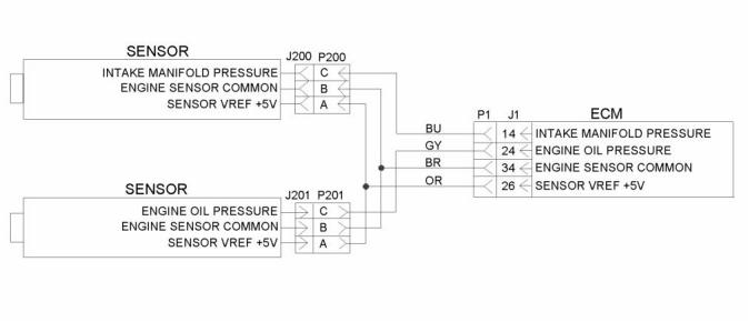
Power Supply for the Pressure
Sensors
g01143335
Illustration 36
Schematic for pressure sensors
The ECM supplies 5.0 ± 0.2 DC volts through the
ECM connector to each sensor. The power supply is
protected against short circuits. A short in a sensor or
a wiring harness will not cause damage to the ECM.
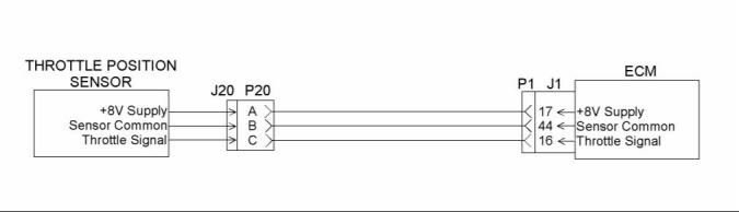
Power Supply for the Throttle
Position Sensor
g01134572
Illustration 37
Schematic for the throttle position sensor
The ECM supplies 8.0 ± 0.4 DC volts through the
ECM connector to the sensor. The power supply is
protected against short circuits. A short in a sensor or
a wiring harness will not cause damage to the ECM.
This document has been printed from SPI². Not for Resale
![]()
![]()
![]()
![]()
SENR9977
29
Systems Operation Section
i02285310
Glossary of Electronic Control
Diagnostic Lamp – A diagnostic lamp is sometimes
called the check engine light. The diagnostic lamp
is used to warn the operator of the presence of an
active diagnostic code.
Terms
Direct Current (DC) – Direct current is the type of
current that flows consistently in only one direction.
Aftermarket Device – An aftermarket device is
a device or an accessory that is installed by the
customer after the engine is delivered.
Duty Cycle – See Pulse Width Modulation.
Electronic Service Tool – The Electronic Service
Tool is used for diagnosing a variety of electronic
controls and the Electronic Service Tool is also used
for programming a variety of electronic controls.
Air-To-Air Aftercooler – An air-to-air aftercooler is a
device that is used on turbocharged engines in order
to cool inlet air that has undergone compression. The
inlet air is cooled after the inlet air passes through
the turbocharger. The inlet air is passed through an
aftercooler (heat exchanger) that uses ambient air for
cooling. The inlet air that has been cooled advances
to the inlet manifold.
Engine Control Module (ECM) – The ECM is the
engine’s control computer. The ECM provides power
to the electronics. The ECM monitors data that is
input from the engine’s sensors. The ECM acts as a
governor in order to control engine rpm.
Before Top Center (BTC) – BTC is the 180 degrees
of crankshaft rotation before the piston reaches the
top center position in the normal direction of rotation.
Estimated Dynamic Timing – Estimated dynamic
timing is the estimate of the actual injection timing
that is calculated by the ECM.
Bypass Circuit – A bypass circuit is a circuit that is
used as a substitute circuit for an existing circuit. A
bypass circuit is typically used as a test circuit.
Enable Signal for the Exhaust Brake – The
exhaust brake enable signal interfaces the ECM to
the engine retarder. This prevents the operation of
the exhaust brake under unsafe engine operating
conditions.
Coolant Temperature Sensor – The coolant
temperature sensor measures the engine coolant
temperature. The sensor sends a signal to the ECM.
The engine’s coolant temperature is used in Cold
Mode operation. Coolant temperature is also used in
order to optimize engine performance.
Failure Mode Identifier (FMI) – The FMI describes
the type of failure that was experienced by the
component. The codes for the FMI were adopted from
the standard practices of SAE (J1587 diagnostics).
Code – See the Diagnostic Code.
Flash Memory – See the Personality Module.
Customer Specified Parameters – A customer
specified parameter is a parameter that can be
changed. A customer specified parameter’s value is
set by the customer. These parameters are protected
by customer passwords.
Fuel Ratio Control (FRC) – The FRC is a limit that
is based on the control of the fuel to the air ratio. The
FRC is used for emission control. When the ECM
senses a higher turbocharger outlet pressure, the
ECM increases the limit for the FRC in order to allow
more fuel into the cylinders.
Data Link – The data link is an electrical connection
that is used to communicate with other electronic
devices that have microprocessors. The data link
is also the communication medium that is used for
programming with the electronic service tool. The
data link is also used for troubleshooting with the
electronic service tool.
Fuel Position – The fuel position is a signal within
the ECM. The signal is from the electronic governor.
The signal goes to the fuel injection control. The
signal is based on the desired engine speed, the
FRC, the rated position, and the actual engine speed.
Harness – The harness is the bundle of wiring that
connects all the components of the electrical engine
system.
Desired RPM – The desired rpm is input to the
electronic governor within the ECM. The electronic
governor uses the signal from the Accelerator Pedal
Position Sensor, the Engine Speed Sensor, the
Cruise Control, and the Customer Parameters in
order to determine desired rpm.
Hertz (Hz) – Hz is the measure of frequency in
cycles per second.
Intake manifold temperature sensor – The
intake manifold temperature sensor is a sensor that
measures the intake air temperature. The sensor
also sends a signal to the ECM.
Diagnostic Code – A diagnostic code is sometimes
called a fault code. A diagnostic code is an indication
of a problem or event in the electrical engine systems.
This document has been printed from SPI². Not for Resale
![]()
30
SENR9977
Systems Operation Section
Open Circuit – An open circuit is a broken electrical
wire connection. The signal or the supply voltage
cannot reach the intended destination.
Original Equipment Manufacturer (OEM) – An
OEM is the manufacturer of a vehicle that utilizes a
Perkins engine.
Parameter – A parameter is a programmable value
which affects the characteristics or the behavior of
the engine and/or vehicle.
Parameter Identifier (PID) – A PID is a numerical
code that contains two digits or three digits. A
numerical code is assigned to each component. The
numerical code identifies data via the data link to the
ECM.
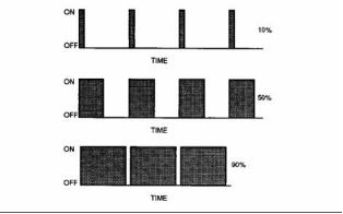
g00284479
Illustration 38
Example Of Pulse Width Modulation
Password – A password is a group of numeric
characters or alphanumeric characters. A password
is designed to restrict the changing of information
in the ECM. The electrical engine systems require
correct customer passwords in order to change
customer specified parameters. The electrical engine
systems require correct factory passwords in order
to clear certain logged events. Factory passwords
are also required in order to change certain engine
specifications.
Rated Fuel Position (“Rated Fuel Pos”) – The
rated fuel position indicates the maximum allowable
fuel position (longest injection pulse). The rated fuel
position will produce rated power for this engine
configuration.
Reference Voltage – The reference voltage is a
regulated voltage that is used by the sensor in order
to generate a signal voltage.
Sensor – A sensor is used to detect a change in
the pressure, in the temperature, or in mechanical
movement. When any of these changes are detected,
a sensor converts the change into an electrical signal.
Personality Module – The personality module is the
module in the ECM which contains all the instructions
(software) for the ECM and performance maps for
a specific horsepower family. Updates and rerates
are accomplished by electronically flashing in new
data. The updates and rerates are flashed in using
the electronic service tool.
Service Program Module (SPM) – The SPM is
a software program on a computer chip that was
programmed at the factory.
Power Take-Off (PTO) – The PTO is operated with
the cruise control switches or dedicated inputs from
the PTO. This mode of operation permits setting
constant engine rpm when the vehicle is not moving
or when the vehicle is moving at slow speeds.
Short Circuit – A short circuit is an electrical circuit
that is mistakenly connected to an undesirable point.
For example, an electrical contact is made with the
frame whenever an exposed wire rubs against a
vehicle’s frame.
Pulse Width Modulation (PWM) – A PWM is a
digital type of electronic signal that corresponds to a
measured variable. The length of the pulse (signal) is
controlled by the measured variable. The variable is
quantified by a certain ratio. This ratio is the percent
of “on-time” that is divided by the percent of “off-time”.
A PWM signal is generated by the Throttle Position
Sensor.
Signal – A signal is a voltage or a wave that is used
to transmit information that is typically from a sensor
to the ECM.
Speed Surge – A speed surge is a sudden brief
change in engine rpm.
Speed-timing Sensor – The speed-timing sensor
is a sensor that provides a Pulse Width Modulated
signal to the ECM. The ECM interprets this signal as
the crankshaft position and the engine speed.
Subsystem – A subsystem is a part of the engine
system that relates to a particular function.
This document has been printed from SPI². Not for Resale
![]()
![]()
SENR9977
31
Systems Operation Section
Supply Voltage – Supply voltage is a constant
voltage that is supplied to a component in order to
provide electrical power for operation. Supply voltage
may be generated by the ECM. Supply voltage may
also be the battery voltage of the vehicle that is
supplied by the vehicle wiring.
“T” Harness – This harness is a test harness that
is designed to permit normal circuit operation and
the measurement of the voltage simultaneously.
Typically, the harness is inserted between the two
ends of a connector.
Throttle Position – The Throttle position is sent
from the accelerator pedal. This signal is interpreted
by the ECM. The throttle position may be used as
part of a power take-off control.
Total Tattletale – The total tattletale is the total
number of changes to all system parameters.
This document has been printed from SPI². Not for Resale
![]()
32
SENR9977
Testing and Adjusting Section
Testing and Adjusting
Section
2. Install a suitable fuel flow tube with a visual sight
gauge in the fuel return line. When possible, install
the sight gauge in a straight section of the fuel line
that is at least 304.8 mm (12 inches) long. Do not
install the sight gauge near the following devices
that create turbulence:
Fuel System
• Elbows
i02242712
• Relief valves
• Check valves
Fuel System - Inspect
Observe the fuel flow during engine cranking.
Look for air bubbles in the fuel. If there is no fuel
that is present in the sight gauge, prime the fuel
system. Refer to Testing and Adjusting, “Fuel
System - Prime” for more information. If the engine
starts, check for air in the fuel at varying engine
speeds. When possible, operate the engine under
the conditions which have been suspect.
A number of the components that send fuel to
the engine can cause low fuel pressure. This can
decrease engine performance.
1. Check the fuel level in the fuel tank. Ensure that
the vent in the fuel cap is not filled with dirt.
2. Check all fuel lines for fuel leakage. The fuel lines
must be free from restrictions and faulty bends.
Verify that the fuel return line is not collapsed.
3. Inspect the fuel filter for excess contamination. If
necessary, install a new fuel filter. Determine the
source of the contamination. Make the necessary
repairs.
4. Service the primary fuel filter (if equipped).
5. Remove any air that may be in the fuel system.
Refer to Testing and Adjusting, “Fuel System -
Prime”.
i01854200
Air in Fuel - Test
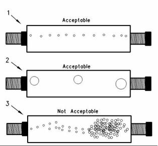
g00578151
This procedure checks for air in the fuel system. This
procedure also assists in finding the source of the air.
Illustration 39
(1) A steady stream of small bubbles with a diameter of
approximately 1.60 mm (0.063 inch) is an acceptable amount
of air in the fuel.
1. Examine the fuel system for leaks. Ensure that
the fuel line fittings are properly tightened. Check
the fuel level in the fuel tank. Air can enter the
fuel system on the suction side between the fuel
transfer pump and the fuel tank.
(2) Bubbles with a diameter of approximately 6.35 mm (0.250 inch)
are also acceptable if there is two seconds to three seconds
intervals between bubbles.
(3) Excessive air bubbles in the fuel are not acceptable.
3. If excessive air is seen in the sight gauge in the
fuel return line, install a second sight gauge at the
inlet to the fuel transfer pump. If a second sight
gauge is not available, move the sight gauge from
the fuel return line and install the sight gauge
at the inlet to the fuel transfer pump. Observe
the fuel flow during engine cranking. Look for air
bubbles in the fuel. If the engine starts, check for
air in the fuel at varying engine speeds.
Work carefully around an engine that is running.
Engine parts that are hot, or parts that are moving,
can cause personal injury.
This document has been printed from SPI². Not for Resale
![]()
![]()
![]()
![]()
SENR9977
33
Testing and Adjusting Section
If excessive air is not seen at the inlet to the fuel
transfer pump, the air is entering the system after
the fuel transfer pump. Refer to the Testing and
Adjusting, “Fuel System - Prime”.
If excessive air is seen at the inlet to the fuel
transfer pump, air is entering through the suction
side of the fuel system.
To avoid personal injury, always wear eye and face
protection when using pressurized air.
NOTICE
To avoid damage, do not use more than 55 kPa (8 psi)
to pressurize the fuel tank.
4. Pressurize the fuel tank to 35 kPa (5 psi). Do
not use more than 55 kPa (8 psi) in order to
avoid damage to the fuel tank. Check for leaks in
the fuel lines between the fuel tank and the fuel
transfer pump. Repair any leaks that are found.
Check the fuel pressure in order to ensure that
the fuel transfer pump is operating properly. For
information about checking the fuel pressure, see
Testing and Adjusting, “Fuel System Pressure -
Test”.
g00923080
Illustration 40
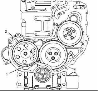
(1) Hole for crankshaft pin
(2) Hole for camshaft pin
1. Remove the valve mechanism cover, the glow
plugs, and the cover for the front housing.
Note: The crankshaft timing pin can be inserted with
the crankshaft pulley still on the engine.
5. If the source of the air is not found, disconnect
the supply line from the fuel tank and connect an
external fuel supply to the inlet of the fuel transfer
pump. If this corrects the problem, repair the fuel
tank or the stand pipe in the fuel tank.
2. Rotate the crankshaft in the normal direction of
the engine until the inlet valve of the No. 4 cylinder
has just opened and the exhaust valve of the No.
4 cylinder has not completely closed.
3. Carefully rotate the crankshaft in the normal
direction of the engine in order to align the hole
in the crankshaft with the hole in the cylinder
block and the timing case. Insert the 27610211
Crankshaft Timing Pin fully into the hole in the
crankshaft web.
i02242740
Finding Top Center Position
for No. 1 Piston
4. Insert the 27610212 Camshaft Timing Pin
through the hole in the camshaft gear and into the
body of the timing case. The engine is set at the
top center position for No. 1 piston.
Table 1
Required Tools
Part
Part Description
Qty
Note: The camshaft gear can rotate a small amount
Number
27610211
27610212
when the pin is installed.
Crankshaft timing pin
Camshaft timing pin
1
1
5. Remove the timing pins from the camshaft gear
and the crankshaft web.
This document has been printed from SPI². Not for Resale
![]()
![]()
![]()
![]()
![]()
![]()
34
SENR9977
Testing and Adjusting Section
i02285307
Fuel Injection Timing - Adjust
6. Insert the 27610032 Timing Pin through the hole
in the fuel pump gear and through the slot in the
hub. Push the timing pin fully into the hole in the
body of the fuel injection pump.
Note: The 27610032 Timing Pin must be a sliding fit
Table 2
in the hole in the body of the fuel injection pump.
Required Tools
Part
Part Description
Qty
Number
27610032
Timing Pin
1
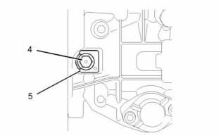
g01143217
Illustration 42
7. Release the locking screw (4). Remove the spacer
(5). Tighten the locking screw (4) to 31 N·m
(23 lb ft).
8. Remove the four setscrews and the four washers
and then remove the fuel pump gear from the hub
on the fuel injection pump.
9. Install the idler gear. Refer to Disassembly and
Assembly, “Idler Gear (Front) - Install”.
g01134728
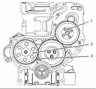
Illustration 41
(1) Hole for timing pin for the fuel pump
(2) Hole for camshaft pin
10. Install the fuel pump gear over the 27610032
Timing Pin and engage with the idler gear.
(3) Hole for crankshaft pin
11. Loosely install the four washers and the four
1. Set the number one piston at top center on
the compression stroke. Refer to Testing and
Adjusting, “Finding Top Center Position for No. 1
Piston” for the correct procedure.
setscrews.
12. Rotate the fuel pump gear counterclockwise in
order to take up the backlash in the gear train
and then tighten the four setscrews to 28 N·m
(20.7 lb ft).
Note: Do not remove the timing pins after finding top
center on the compression stroke.
13. Release the locking screw (4). Install the spacer
(5) under the head of the locking screw. Tighten
the locking screw (4) to 12 N·m (9 lb ft).
2. Remove the four setscrews and the four washers
and then remove the fuel pump gear from the hub
on the fuel injection pump.
14. Remove all three timing pins and install the
3. Remove the idler gear. Refer to Disassembly and
removed components.
Assembly, “Idler Gear (Front) - Remove”.
15. Check the fuel injection timing again. Refer to
Testing and Adjusting, “Fuel Injection Timing -
Check”.
4. Install the fuel pump gear on the hub of the fuel
injection pump shaft and install the four setscrews
and the four washers.
5. Turn the fuel pump gear until the slot in the hub
is aligned with the hole in the fuel injection pump
body.
This document has been printed from SPI². Not for Resale
![]()

![]()
![]()
SENR9977
35
Testing and Adjusting Section
i02253244
Fuel Injection Timing - Check
4. Remove all three timing pins and install the
removed components.
i02243111
Fuel Quality - Test
Table 3
Required Tools
Part
Part Description
Qty
Number
Use the following procedure to test for problems
regarding fuel quality:
27610032
Timing Pin
1
1. Determine if water and/or contaminants are
present in the fuel. Check the water separator (if
equipped). If a water separator is not present,
proceed to Step 2. Drain the water separator, if
necessary. A full fuel tank minimizes the potential
for overnight condensation.
1. Set the number one piston at top center on
the compression stroke. Refer to Testing and
Adjusting, “Finding Top Center Position for No. 1
Piston” for the correct procedure.
Note: Do not remove the timing pins after finding top
center on the compression stroke.
Note: A water separator can appear to be full of fuel
when the water separator is actually full of water.
2. Determine if contaminants are present in the
fuel. Remove a sample of fuel from the bottom
of the fuel tank. Visually inspect the fuel sample
for contaminants. The color of the fuel is not
necessarily an indication of fuel quality. However,
fuel that is black, brown, and/or similar to sludge
can be an indication of the growth of bacteria or
oil contamination. In cold temperatures, cloudy
fuel indicates that the fuel may not be suitable for
operating conditions.
Refer to Operation and Maintenance Manual,
“Refill Capacities and Recommendations” for
more information.
3. If fuel quality is still suspected as a possible
cause to problems regarding engine performance,
disconnect the fuel inlet line, and temporarily
operate the engine from a separate source of
fuel that is known to be good. This will determine
if the problem is caused by fuel quality. If fuel
quality is determined to be the problem, drain the
fuel system and replace the fuel filters. Engine
performance can be affected by the following
characteristics:
g01134728
Illustration 43
(1) Hole for timing pin for the fuel pump
(2) Hole for camshaft pin
(3) Hole for crankshaft pin
2. Insert the 27610032 Timing Pin through the hole
in the fuel pump gear and through the slot in the
hub. Push the timing pin fully into the hole in the
body of the fuel injection pump.
• Cetane number of the fuel
• Air in the fuel
Note: The 27610032 Timing Pin must be a sliding fit
• Other fuel characteristics
in the hole in the body of the fuel injection pump.
3. The timing of the fuel pump is correct when all
three of the timing pins are in the position.
Note: If the 27610032 Timing Pin cannot be pushed
into the body of the fuel injection pump, then the fuel
pump gear must be realigned on the hub on the fuel
injection pump shaft. Refer to Testing and Adjusting,
“Fuel Injection Timing - Adjust”.
This document has been printed from SPI². Not for Resale
![]()

![]()

36
SENR9977
Testing and Adjusting Section
i02253606
i02253617
Fuel System Pressure - Test
Fuel System - Prime
If air enters the fuel system, the air must be purged
before the engine can be started. Air can enter the
fuel system when the following events occur:
• The fuel tank is empty or the tank has been partially
drained during normal operation.
• The low pressure fuel lines are disconnected.
• A leak exists in the low pressure fuel system during
engine operation.
• The fuel filter or the fuel pump is replaced.
• The high pressure fuel lines are disconnected.
g01135042
Illustration 45
(1) Fuel transfer pump
Use the following procedure in order to remove air
from the fuel system:
(2) Fuel filter housing
(3) Outlet for the supply for the fuel injection pump
(4) Outlet for the return to the fuel tank
1. Remove the cover for the fuel injectors.
The pressure test measures the output pressure of
the fuel transfer pump. Low fuel pressure and starting
difficulty may be indications of problems with the fuel
transfer pump.
2. Turn the key to the RUN position for three minutes
in order to energize the fuel priming pump. Do not
start the engine. Then turn the key to the OFF
position.
Check the Function of the Fuel
Transfer Pump
1. Make a note of the location of the fuel lines from
the fuel transfer pump. Remove the two lines from
the outlets (3) and (4).
2. Connect two lengths of 5/16 inch rubber hose
to outlets (3) and (4). Place the hoses into a
suitable container that is capable of holding 3.0 L
(0.66 Imp gal) of fuel.
3. Energize the fuel transfer pump until a constant
flow of fuel is running from the outlet for the supply
for the fuel injection pump.
g01135020
Illustration 44
(1) Connections for the high pressure fuel lines
Note: The flow from the outlet for the return for the
fuel tank will have a slower flow rate.
3. Loosen the connections for the high pressure fuel
lines (1).
4. Measure the combined flow of both outlets with
a stopwatch. Fuel flow should be a minimum of
2.0 L (0.44 Imp gal) per minute.
4. Operate the electric starter motor until fuel that is
free of air comes from the connections.
5. If the combined flow is less than 2.0 L
(0.44 Imp gal) per minute, replace the fuel transfer
pump.
5. Tighten the connections for the high pressure fuel
lines to a torque of 30 N·m (22 lb ft).
6. Start the engine and check for leaks.
7. Install the cover for the fuel injectors.
6. Reconnect the outlet lines in the correct positions.
This document has been printed from SPI². Not for Resale
![]()
![]()
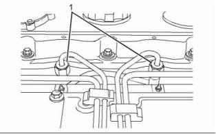
![]()
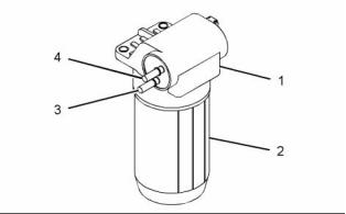
SENR9977
37
Testing and Adjusting Section
7. Start the engine and check for any leakage of fuel
or air from the fuel lines.
Check the Function of the Pressure
Regulator
1. Remove the fuel line from the outlet for the supply
for the fuel injection pump (3).
2. Install a pipe with a tap for a pressure gauge.
Connect a 0 to 80 kPa (0 to 12 psi) pressure
gauge.
3. Start the engine and run the engine at idle for two
minutes in order to remove any trapped air.
4. Record the pressure reading at idle and at rated
speed. The minimum pressure reading should be
the following values:
Bosch VP30
Idle ................................... 27.5 kPa (3.98 psi)
Rated speed ....................... 24 kPa (3.48 psi)
Note: The maximum pressure reading at the inlet to
the fuel injection pump is 80 kPa (12 psi).
5. Reconnect the fuel line. Run the engine at idle for
two minutes in order to remove any trapped air.
Check for the following issues if the pressures are
outside of the above specifications.
• All electrical connections are installed correctly.
• There are no leaks in the fuel lines or connections.
• The O-ring on fuel filter housing (2) does not leak.
This document has been printed from SPI². Not for Resale
![]()
38
SENR9977
Testing and Adjusting Section
Air Inlet and Exhaust
System
i02254115
Wastegate - Test
i02253770
Air Inlet and Exhaust System
- Inspect
Hot engine components can cause injury from
burns. Before performing maintenance on the
engine, allow the engine and the components to
cool.
A general visual inspection should be made to the air
inlet and exhaust system. Make sure that there are
no signs of leaks in the system.
There will be a reduction in the performance of the
engine if there is a restriction in the air inlet system or
the exhaust system.
NOTICE
Keep all parts clean from contaminants.
Contaminants may cause rapid wear and shortened
component life.
Hot engine components can cause injury from
burns. Before performing maintenance on the
engine, allow the engine and the components to
cool.
Making contact with a running engine can cause
burns from hot parts and can cause injury from
rotating parts.
When working on an engine that is running, avoid
contact with hot parts and rotating parts.
1. Inspect the engine air cleaner inlet and ducting
in order to ensure that the passageway is not
blocked or collapsed.
2. Inspect the engine air cleaner element. Replace a
dirty element with a clean element.
g01135413
Illustration 46
3. Check for evidence of dirt on the clean side of the
engine air cleaner element. If dirt is observed,
contaminants are flowing past the element.
Note: The turbocharger is a nonserviceable item.
The pressure for the wastegate can be checked, but
not adjusted.
1. Use a suitable dial indicator (1). Align the dial
gauge to the actuator rod (2).
2. Remove the air hose to the actuator . Install an air
line (3) that can be adjusted in order to give the
correct pressure.
This document has been printed from SPI². Not for Resale
![]()
![]()
![]()
![]()
![]()
![]()
![]()
![]()
![]()
![]()
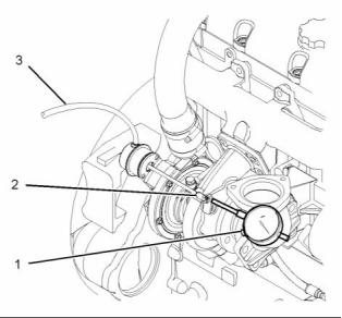
SENR9977
39
Testing and Adjusting Section
3. Slowly apply air pressure to the wastegate so
that the actuator rod moves 1.0 mm (0.039 inch).
The air pressure should be within 107 to 117 kPa
(15.5 to 17.0 psi). Ensure that the dial indicator
returns to zero when the air pressure is released.
Repeat the test several times. This will ensure that
an accurate reading is obtained.
i02254773
Engine Valve Lash -
Inspect/Adjust
4. For more information on installing a new
turbocharger, contact your Perkins dealer or your
Perkins distributor.
To prevent possible injury, do not use the starter
to turn the flywheel.
Hot engine components can cause burns. Allow
additional time for the engine to cool before mea-
suring valve clearance.
i01888954
Compression - Test
Valve Lash Setting
The cylinder compression test should only be used in
order to compare the cylinders of an engine. If one or
more cylinders vary by more than 350 kPa (51 psi),
the cylinder and related components may need to
be repaired.
Valve lash setting
Inlet valve ........................... 0.2 mm (0.008 inch)
Exhaust valve ................... 0.45 mm (0.018 inch)
A compression test should not be the only method
which is used to determine the condition of an engine.
Other tests should also be conducted in order to
determine if the adjustment or the replacement of
components is required.
Refer to Systems Operation, “Engine Design” for the
location of the cylinder valves.
Valve Lash Adjustment
If the valve lash requires adjustment several times
in a short period of time, excessive wear exists in
a different part of the engine. Find the problem and
make necessary repairs in order to prevent more
damage to the engine.
Before the performance of the compression test,
make sure that the following conditions exist:
• The battery is in good condition.
• The battery is fully charged.
Not enough valve lash can be the cause of rapid
wear of the camshaft and valve lifters. Not enough
valve lash can indicate that the seats for the valves
are worn.
• The starting motor operates correctly.
• The valve lash is set correctly.
• All fuel injectors are removed.
• The fuel supply is disconnected.
Valves become worn due to the following causes:
• Fuel injectors that operate incorrectly
• Excessive dirt and oil are present on the filters for
the inlet air.
1. Install a gauge for measuring the cylinder
compression in the hole for a fuel injector.
• Incorrect fuel settings on the fuel injection pump.
2. Operate the starting motor in order to turn the
engine. Record the maximum pressure which is
indicated on the compression gauge.
• The load capacity of the engine is frequently
exceeded.
3. Repeat Steps 1 and 2 for all cylinders.
Too much valve lash can cause broken valve stems,
springs, and spring retainers. Too much valve lash
can be an indication of the following problems:
• Worn camshaft and valve lifters
• Worn rocker arms
• Bent pushrods
This document has been printed from SPI². Not for Resale
![]()
![]()
![]()
40
SENR9977
Testing and Adjusting Section
• Broken socket on the upper end of a pushrod
• Loose adjustment screw for the valve lash
b. Place the appropriate feeler gauge (2) between
the rocker arm and the valve. Turn adjustment
screw (1) while the valve adjustment screw
locknut is being held from turning. Adjust the
valve lash until the correct specification is
achieved.
If the camshaft and the valve lifters show rapid wear,
look for fuel in the lubrication oil or dirty lubrication
oil as a possible cause.
c. After each adjustment, tighten the valve
adjustment screw locknut while adjustment
screw (1) is being held from turning.
The valve lash is measured between the top of the
valve stem and the rocker arm lever.
Note: An adjustment is not necessary if the
measurement of the valve lash is in the acceptable
range. Inspect the valve lash while the engine is
stopped. The temperature of the engine does not
change the valve lash setting.
3. Rotate the crankshaft in a clockwise direction that
is viewed from the front of the engine. When the
inlet valve of the No. 2 cylinder has opened and
the exhaust valve of the No. 2 cylinder has not
completely closed measure the valve lash of the
inlet valve and the exhaust valve of the No. 3
cylinder.
Note: When the following procedures are performed,
the front housing must be installed.
If adjustment is necessary, refer to Steps 2.a, 2.b,
and 2.c above.
4. Rotate the crankshaft in a clockwise direction that
is viewed from the front of the engine. When the
inlet valve of the No. 1 cylinder has opened and
the exhaust valve of the No. 1 cylinder has not
completely closed measure the valve lash of the
inlet valve and the exhaust valve of the No. 4
cylinder.
If adjustment is necessary, refer to Steps 2.a, 2.b,
and 2.c above.
5. Rotate the crankshaft in a clockwise direction that
is viewed from the front of the engine. When the
inlet valve of the No. 3 cylinder has opened and
the exhaust valve of the No. 3 cylinder has not
completely closed measure the valve lash of the
inlet valve and the exhaust valve of the No. 2
cylinder.
g01016764
Illustration 47
Setting the valve lash
(1) Adjustment screw
(2) Feeler gauge
If adjustment is necessary, refer to Steps 2.a, 2.b,
and 2.c above.
6. Install the valve mechanism cover. Refer to
Disassembly and Assembly, “Valve Mechanism
Cover - Remove and Install”.
1. Remove the valve mechanism cover. Refer to
Disassembly and Assembly, “Valve Mechanism
Cover - Remove and Install”.
2. Rotate the crankshaft in a clockwise direction that
is viewed from the front of the engine. When the
inlet valve of the No. 4 cylinder has opened and
the exhaust valve of the No. 4 cylinder has not
completely closed measure the valve lash of the
inlet valve and the exhaust valve of the No. 1
cylinder. If necessary, make adjustment.
a. Loosen the valve adjustment screw locknut
that is on adjustment screw (1).
This document has been printed from SPI². Not for Resale
![]()
![]()
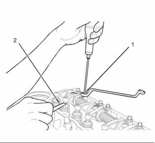
SENR9977
41
Testing and Adjusting Section
i01889422
3. Inspect the valves for cracks and other damage.
Check the valve stems for wear. Check that the
valve springs are the correct length under the test
force. Refer to Specifications, “Cylinder Head
Valves” for the dimensions and tolerances of the
valves and the valve springs.
Valve Depth - Inspect
Table 4
Required Tools
i01938952
Valve Guide - Inspect
Part
Part Description
Qty
Number
21825617
21825496
Dial gauge
1
1
Perform this inspection in order to determine if a
valve guide should be replaced.
Dial gauge holder
g00983531
Illustration 48
Measurement of the valve depth
(1) 21825617 Dial gauge
(2) 21825496 Dial gauge holder
1. Use the dial gauge (1) with the dial gauge holder
(2) to check the depths of the inlet valves and
the exhaust valves below the face of the cylinder
head. Use the cylinder head face (3) to zero the
dial gauge (1).
g00986821
Illustration 49
(1) Valve guide
(2) Radial movement of the valve in the valve guide
(3) Valve stem
(4) Dial indicator
2. Position the dial gauge holder (2) and the dial
gauge (1) in order to measure the valve depth.
Measure the depth of the inlet valve and the
exhaust valve before the valve springs are
removed.
(5) Valve head
1. Place a new valve in the valve guide.
2. Place a suitable dial indicator with the magnetic
base on the face of the cylinder head.
Refer to Specifications, “Cylinder Head Valves”
for the minimum, the maximum, and the service
wear limits for the valve depth below the cylinder
head face.
3. Lift the edge of the valve head to a distance of
15.0 mm (0.60 inch).
4. Move the valve in a radial direction away from the
dial indicator. Make sure that the valve moves
away from the dial indicator as far as possible.
Position the contact point of the dial indicator on
the edge of the valve head. Set the position of the
needle of the dial indicator to zero.
If the valve depth below the cylinder head face
exceeds the service limit, use a new valve to
check the valve depth. If the valve depth still
exceeds the service limit, renew the cylinder head
or renew the valve seat inserts (if equipped). If the
valve depth is within the service limit with a new
valve, renew the valves.
This document has been printed from SPI². Not for Resale
![]()
![]()
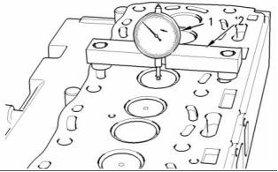
![]()
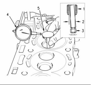
42
SENR9977
Testing and Adjusting Section
5. Move the valve in a radial direction toward the dial
indicator as far as possible. Note the distance of
movement which is indicated on the dial indicator.
If the distance is greater than the maximum
clearance of the valve in the valve guide, replace
the valve guide.
When new valve guides are installed, new valves
and new valve seat inserts must be installed.
Valve guides and valve seat inserts are supplied
as an unfinished part. The unfinished valve guides
and unfinished valve seat inserts are installed in
the cylinder head. Then, the valve guides and
valve inserts are cut and reamed in one operation
with special tooling.
Refer to Specifications, “Cylinder Head Valves” for
the maximum clearance of the valve in the valve
guide.
This document has been printed from SPI². Not for Resale
![]()
SENR9977
43
Testing and Adjusting Section
Lubrication System
Engine Oil Pressure - Test
Low Oil Pressure
Perform the following procedures in order to inspect
the oil pump for clearances and torques.
Refer to the Specifications Module, “Engine Oil
Pump”.
i01854908
1. Remove the oil pump from the engine. Refer to
the Disassembly and Assembly, “Engine Oil Pump
- Remove”. Remove the cover of the oil pump.
2. Remove the outer rotor. Clean all of the parts.
Look for cracks in the metal or other damage.
The following conditions will cause low oil pressure.
• The oil level is low in the crankcase.
• A restriction exists on the oil suction screen.
• Connections in the oil lines are leaking.
• The connecting rod or the main bearings are worn.
• The rotors in the oil pump are worn.
• The oil pressure relief valve is operating incorrectly.
A worn oil pressure relief valve can allow oil to leak
through the valve which lowers the oil pressure.
Refer to the Specifications Module, “Engine Oil Relief
Valve” for the correct operating pressure and other
information.
When the engine runs at the normal temperature for
operation and at high idle, the oil pressure must be
a minimum of 280 kPa (40 psi). A lower pressure is
normal at low idle.
g00985779
Illustration 50
Clearance for the outer rotor body
(1) Measure the clearance of the outer rotor to the body.
A suitable pressure gauge can be used in order to
test the pressure of the lubrication system.
3. Install the outer rotor. Measure the clearance of
the outer rotor to the body (1).
High Oil Pressure
High oil pressure can be caused by the following
conditions.
• The spring for the oil pressure relief valve is
installed incorrectly.
• The plunger for the oil pressure relief valve
becomes jammed in the closed position.
• Excessive sludge exists in the oil which makes the
viscosity of the oil too high.
i01893791
Engine Oil Pump - Inspect
If any part of the oil pump is worn enough in order to
affect the performance of the oil pump, the oil pump
must be replaced.
This document has been printed from SPI². Not for Resale
![]()
![]()
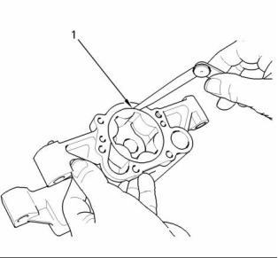
44
SENR9977
Testing and Adjusting Section
i01126690
Excessive Bearing Wear -
Inspect
When some components of the engine show bearing
wear in a short time, the cause can be a restriction in
an oil passage.
An engine oil pressure indicator may show that there
is enough oil pressure, but a component is worn
due to a lack of lubrication. In such a case, look at
the passage for the oil supply to the component.
A restriction in an oil supply passage will not allow
enough lubrication to reach a component. This will
result in early wear.
i01794028
Excessive Engine Oil
g00985780
Illustration 51
Clearance for the inner rotor
Consumption - Inspect
(2) Measure the clearance of the inner rotor to the outer rotor.
4. Measure the clearance of the inner rotor to the
outer rotor (2).
Engine Oil Leaks on the Outside of
the Engine
Check for leakage at the seals at each end of the
crankshaft. Look for leakage at the gasket for the
engine oil pan and all lubrication system connections.
Look for any engine oil that may be leaking from
the crankcase breather. This can be caused by
combustion gas leakage around the pistons. A dirty
crankcase breather will cause high pressure in the
crankcase. A dirty crankcase breather will cause the
gaskets and the seals to leak.
Engine Oil Leaks into the
Combustion Area of the Cylinders
Engine oil that is leaking into the combustion area of
the cylinders can be the cause of blue smoke. There
are several possible ways for engine oil to leak into
the combustion area of the cylinders:
g00989217
Illustration 52
• Leaks between worn valve guides and valve stems
5. Measure the end play of the rotor with a straight
• Worn components or damaged components
(pistons, piston rings, or dirty return holes for the
engine oil)
edge and a feeler gauge (3).
6. Clean the top face of the oil pump and the bottom
face of the cover. Install the cover on the oil
pump. Install the oil pump on the engine. Refer to
Disassembly and Assembly, “Engine Oil Pump -
Install”.
• Incorrect installation of the compression ring and/or
the intermediate ring
• Leaks past the seal rings in the turbocharger shaft
This document has been printed from SPI². Not for Resale
![]()
![]()
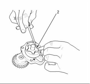
![]()
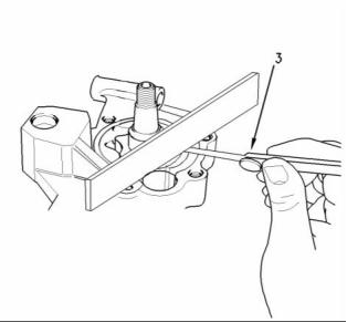
SENR9977
45
Testing and Adjusting Section
• Overfilling of the crankcase
• Wrong dipstick or guide tube
• Sustained operation at light loads
Excessive consumption of engine oil can also
result if engine oil with the wrong viscosity is used.
Engine oil with a thin viscosity can be caused by fuel
leakage into the crankcase or by increased engine
temperature.
i01945015
Increased Engine Oil
Temperature - Inspect
Look for a restriction in the oil passages of the oil
cooler (if equipped). The oil temperature may be
higher than normal when the engine is operating. In
such a case, the oil cooler may have a restriction.
A restriction in the oil cooler will not cause low oil
pressure in the engine.
This document has been printed from SPI². Not for Resale
![]()
46
SENR9977
Testing and Adjusting Section
Cooling System
8. Check the filler cap. A pressure drop in the cooling
system can cause the boiling point to be lower.
This can cause the cooling system to boil. Refer
to Testing and Adjusting, “Cooling System - Test”.
i02274237
Cooling System - Check
(Overheating)
9. Check the cooling system hoses and clamps.
Damaged hoses with leaks can normally be seen.
Hoses that have no visual leaks can soften during
operation. The soft areas of the hose can become
kinked or crushed during operation. These areas
of the hose can cause a restriction in the coolant
flow. Hoses become soft and/or get cracks
after a period of time. The inside of a hose can
deteriorate, and the loose particles of the hose
can cause a restriction of the coolant flow.
Above normal coolant temperatures can be caused
by many conditions. Use the following procedure
to determine the cause of above normal coolant
temperatures:
1. Check the coolant level in the cooling system. If
the coolant level is too low, air will get into the
cooling system. Air in the cooling system will
cause a reduction in coolant flow and bubbles
in the coolant. Air bubbles will keep the coolant
away from the engine parts, which will prevent the
transfer of heat to the coolant. Low coolant level is
caused by leaks or incorrectly filling the expansion
tank.
10. Check for a restriction in the air inlet system. A
restriction of the air that is coming into the engine
can cause high cylinder temperatures. High
cylinder temperatures require higher than normal
temperatures in the cooling system.
11. Check for a restriction in the exhaust system.
A restriction of the air that is coming out of the
engine can cause high cylinder temperatures.
2. Check that the exterior of the radiator is not
a. Make a visual inspection of the exhaust system.
blocked with debris.
b. Check for damage to exhaust piping. Check for
damage to the exhaust elbow. If no damage
is found, check the exhaust system for a
restriction.
3. Check that the drive belts are not loose. Refer to
Testing and Adjusting, “V-Belt - Test”.
4. Check that the fan is correctly installed and that
the fan is not damaged.
12. Check the water temperature regulator. A water
temperature regulator that does not open, or a
water temperature regulator that only opens part
of the way can cause overheating. Refer to Testing
and Adjusting, “Water Temperature Regulator -
Test”.
5. Check for air in the cooling system. Air can enter
the cooling system in different ways. The most
common causes of air in the cooling system
are not filling the cooling system correctly and
combustion gas leakage into the cooling system.
Combustion gas can get into the system through
inside cracks, a damaged cylinder head, or
a damaged cylinder head gasket. Air in the
cooling system causes a reduction in coolant
flow and bubbles in the coolant. Air bubbles keep
the coolant away from the engine parts, which
prevents the transfer of heat to the coolant.
13. Check the water pump. A water pump with a
damaged impeller does not pump enough coolant
for correct engine cooling. Remove the water
pump and check for damage to the impeller.
14. Consider high outside temperatures. When
outside temperatures are too high for the rating
of the cooling system, there is not enough of
a temperature difference between the outside
air and coolant temperatures. The maximum
temperature of the ambient air that enters the
engine should not exceed 50 °C (120 °F).
6. Check the sending unit. In some conditions, the
temperature sensor in the engine sends signals
to a sending unit. The sending unit converts these
signals to an electrical impulse which is used by a
mounted gauge. If the sending unit malfunctions,
the gauge can show an incorrect reading. Also if
the electric wire breaks or if the electric wire shorts
out, the gauge can show an incorrect reading.
15. When a load that is applied to the engine is too
large, the engine rpm does not increase with an
increase of fuel. This lower engine rpm causes
a reduction in coolant flow through the system.
This combination of less air and less coolant flow
during high input of fuel will cause above normal
heating.
7. Check the radiator for a restriction to coolant flow.
Check the radiator for debris, dirt, or deposits on
the inside of the core. Debris, dirt, or deposits will
restrict the flow of coolant through the radiator.
This document has been printed from SPI². Not for Resale
![]()