 English
 Espaol
 Franais
 阿拉伯
阿拉伯 中文
中文 Deutsch
 Italiano
 Português
 日本
日本 韩国
韩国 български
 hrvatski
 esky
esky Dansk
Dansk Nederlands
 suomi
suomi Ελληνικ
 印度
印度 norsk
norsk Polski
 Roman
Roman русский
 Svenska
珀金斯Perkins1103D-33(T)(TA)测试调整供应商,珀金斯Perkins1103D-33(T)(TA)测试调整技术价格规格咨询服务,珀金斯Perkins1103D-33(T)(TA)测试调整零配件供应,珀金斯Perkins1103D-33(T)(TA)测试调整售后服务中心,珀金斯Perkins1103D-33(T)(TA)测试调整,珀金斯Perkins1103D-33(T)(TA)测试调整详细的技术参数,

产品中心
珀金斯Perkins1103D-33(T)(TA)测试调整(英文)
详细描述
Systems Operation
Testing and Adjusting
1103D Industrial Engine
XK (Engine)
XL (Engine)
XM (Engine)
This document has been printed from SPI². Not for Resale

![]()
![]()
![]()
![]()
Important Safety Information
Most accidents tha t involve produc t op eration, ma intena nc e and repair are caus ed by failure to
ob serve basic safety rules or precautions . An accident can often be avoided by recog nizing pote ntially
ha za rdous situations before an accident oc curs . A person mus t be alert to pote ntial ha za rds. This
person should also ha ve the ne cessary training, skills and tools to perform the se func tions properly.
Improper operation, lubrication, maintenance or repair of this product can be dangerous and
could result in injury or death.
Do not operate or perform any lubrication, maintenance or repair on this product, until you have
read and understood the operation, lubrication, maintenance and repair information.
Sa fety precautions and warning s are provided in this ma nua l and on the produc t. If the se ha za rd
warning s are not he eded, bod ily injury or death could oc cur to you or to othe r persons .
The ha za rds are identified by the “Safety Alert Symb ol” and followed by a “Signa l Word” suc h as
“DANGER”, “WARNING” or “CAUTION”. The Sa fety Alert “WARNING” label is shown below.
The me aning of this safety alert symb ol is as follows:
Attention! Become Alert! Your Safety is Involved.
The me ssage tha t appears und er the warning explains the ha za rd and can be either written or
pictorially presente d.
Op erations tha t ma y caus e produc t dama ge are identified by “NOTICE” labels on the produc t and in
this pub lication.
Perkins cannot anticipate every possible circumstance that might involve a potential hazard. The
warnings in this publication and on the product are, therefore, not all inclusive. If a tool, procedure,
work method or operating technique that is not specifically recommended by Perkins is used,
you must satisfy yourself that it is safe for you and for others. You should also ensure that the
product will not be damaged or be made unsafe by the operation, lubrication, maintenance or
repair procedures that you choose.
The informa tion, specifications , and illustrations in this pub lication are on the basis of informa tion tha t
was available at the time tha t the pub lication was written. The specifications , torque s, pressure s,
me asure me nts , adjustme nts , illustrations , and othe r items can cha ng e at any time. These cha ng es can
affect the service tha t is given to the produc t. Ob tain the comp lete and mos t current informa tion before
you start any job. Pe rkins dealers or Pe rkins distributors ha ve the mos t current informa tion available.
When replacement parts are required for this
product Perkins recommends using Perkins
replacement parts.
Failure to heed this warning can lead to prema-
ture failures, product damage, personal injury or
death.
This document has been printed from SPI². Not for Resale
![]()
![]()
KENR6912
3
Table of Contents
Table of Contents
Electrical System
Alternator - Test .................................................... 44
Battery - Test ......................................................... 44
Electric Starting System - Test .............................. 45
Glow Plugs - Test .................................................. 47
V-Belt - Test .......................................................... 47
Systems Operation Section
Engine Design ....................................................... 4
General Information ................................................ 4
Fuel System ........................................................... 7
Air Inlet and Exhaust System ................................. 9
Lubrication System .............................................. 13
Cooling System .................................................... 15
Basic Engine ......................................................... 15
Electrical System ................................................. 16
Index Section
Index ..................................................................... 49
Testing and Adjusting Section
Fuel System
Fuel System - Inspect ........................................... 18
Air in Fuel - Test .................................................... 18
Finding Top Center Position for No. 1 Piston ........ 19
Fuel Injection Pump Timing - Check ..................... 20
Fuel Injection Pump Timing - Adjust ..................... 20
Fuel Quality - Test ................................................. 20
Fuel System - Prime ............................................. 21
Fuel System Pressure - Test ................................. 21
Air Inlet and Exhaust System
Air Inlet and Exhaust System - Inspect ................. 23
Wastegate - Test ................................................... 23
Exhaust Temperature - Test .................................. 24
Engine Crankcase Pressure (Blowby) - Test ........ 24
Compression - Test ............................................... 24
Engine Valve Lash - Inspect/Adjust ...................... 25
Valve Depth - Inspect ............................................ 27
Valve Guide - Inspect ............................................ 27
Lubrication System
Engine Oil Pressure - Test .................................... 29
Engine Oil Pump - Inspect .................................... 29
Excessive Bearing Wear - Inspect ........................ 30
Excessive Engine Oil Consumption - Inspect ....... 30
Increased Engine Oil Temperature - Inspect ........ 31
Cooling System
Cooling System - Check (Overheating) ................ 32
Cooling System - Inspect ...................................... 33
Cooling System - Test ........................................... 33
Engine Oil Cooler - Inspect ................................... 35
Water Temperature Regulator - Test ..................... 36
Basic Engine
Piston Ring Groove - Inspect ................................ 37
Connecting Rod - Inspect ..................................... 38
Connecting Rod Bearings - Inspect ...................... 38
Main Bearings - Inspect ........................................ 38
Cylinder Block - Inspect ........................................ 38
Cylinder Head - Inspect ........................................ 39
Piston Height - Inspect .......................................... 40
Flywheel - Inspect ................................................. 40
Flywheel Housing - Inspect ................................... 41
Gear Group - Inspect ............................................ 43
This document has been printed from SPI². Not for Resale
![]()
4
Systems Operation Section
KENR6912
Systems Operation Section
The front of the engine is opposite the flywheel end
of the engine. The left side of the engine and the right
side of the engine are determined from the flywheel
end. Number 1 cylinder is the front cylinder of the
engine.
i02873613
Engine Design
i02873620
General Information
Engine Description
Note: When you are ordering new parts, refer to the
engine identification number in order to receive the
correct parts. Refer to Operation and Maintenance
Manual, “Product Identification Information” for the
correct numbers for your engine.
The engine cylinders are arranged in-line. The
engines are controlled by a mechanically governed
fuel injection pump.
g01223241
Illustration 1
(A) Exhaust valve
(B) Inlet valve
The cylinder head assembly has one inlet valve and
one exhaust valve for each cylinder. Each valve has
one valve spring. The pistons have two compression
rings and an oil control ring.
1103D Industrial Engine Specification
Type .......................... Three cylinder and four stroke
Type of combustion ............................ Direct injection
Bore ......................................... 105 mm (4.133 inch)
Stroke ........................................ 127 mm (5.00 inch)
It is important to ensure the correct piston height so
that the piston does not contact the cylinder head.
The correct piston height also ensures the efficient
combustion of fuel.
The 1103D engine crankshaft has four main journals.
End play is controlled by thrust washers that are
located on both sides of the number three main
bearing.
Displacement ...................................... 3.3 L (201 in )
3
Compression ratio
The timing case has a hole that corresponds with a
hole in the crankshaft. Use an alignment pin to find
top center (TC). The camshaft gear has a timing
hole that corresponds with a timing hole in the timing
case. The timing holes ensure that the camshaft and
the crankshaft are in time with each other.
Naturally aspirated ........................................ 19.25:1
Turbocharged ................................................ 18.23:1
Turbocharged aftercooled ............................... 18.2:1
Number of cylinders ................................................ 3
Cylinder arrangement ..................................... In-line
Firing order ..................................................... 1, 2, 3
The crankshaft gear rotates the idler gear. The idler
gear rotates the camshaft gear and the fuel injection
pump gear. The idler gear for the engine oil pump is
rotated by the crankshaft gear. This idler rotates the
engine oil pump.
When the crankshaft is viewed from the front of
the engine, the crankshaft rotates in the following
direction. ................................................... Clockwise
The fuel injection pump is a gear-driven pump that
is mounted to the back of the front housing. The
fuel transfer pump is electrically operated. The fuel
transfer pump has an integral fuel filter. The fuel
transfer pump is usually located on the left hand side
of the cylinder block. Some applications may have
the fuel transfer pump and the water separator (if
equipped) relocated off the engine.
This document has been printed from SPI². Not for Resale
![]()
![]()
KENR6912
5
Systems Operation Section
The oil pump is driven by an idler gear. The engine
oil pump sends lubricating oil to the main oil gallery.
The oil relief valve is internal to the oil pump.
Coolant from the bottom of the radiator passes
through the water pump. The water pump is driven
by the Fuel injection pump gear.
Lifting the Engine
NOTICE
Failure to follow recommended procedures for han-
dling or transporting engines can lead to engine dam-
age.
To avoid possible engine damage, use the following
procedure.
When you are lifting or moving the engine, use the
following procedures in order to prevent engine
damage.
1. Do not tilt the engine to an extreme angle unless
the lubricating oil is first drained from the oil pan.
2. Do not turn the engine onto a side or an end
surface unless the lubricating oil is first drained
from the oil pan.
3. If the oil is not drained prior to tilting the engine or
turning the engine onto a side or an end surface,
the lubricating oil from the oil pan can flow into
the intake manifold and the cylinder bores. This
situation could cause a hydraulic lock in the
engine. Hydraulic lock can severely damage the
engine.
4. The engine oil should be refilled to the correct
level before the engine is started.
This document has been printed from SPI². Not for Resale
![]()
![]()
![]()
6
Systems Operation Section
KENR6912
1103D Engine Model Views
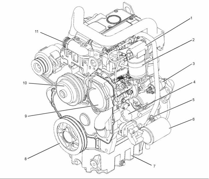
g01399674
Illustration 2
Typical example
(1) Fuel transfer pump
(2) Fuel filter
(5) Dipstick
(6) Oil filter
(9) Water pump
(10) Fan pulley
(3) Starting motor
(4) Oil filler cap
(7) Oil pan
(8) Crankshaft pulley
(11) Water temperature regulator housing
This document has been printed from SPI². Not for Resale
![]()
![]()
KENR6912
7
Systems Operation Section
g01403711
Illustration 3
Typical example
(1) Alternator
(2) Turbocharger
(3) Turbocharger oil supply
(4) Turbocharger oil drain
(5) Exhaust manifold
The fuel transfer pump draws fuel from the fuel tank
and through the water separator. When the fuel goes
through the water separator, any water in the fuel will
go to the bottom of the bowl. The fuel transfer pump
sends the fuel at a low pressure to the fuel filter. From
the fuel filter, the fuel goes through the supply line to
the fuel injection pump.
i02873638
Fuel System
The Delphi DP210 fuel injection pump is installed
on the naturally aspirated 1103D engine. The
Delphi DP310 fuel injection pump is installed on the
turbocharged 1103D engine.
This document has been printed from SPI². Not for Resale
![]()
![]()

8
Systems Operation Section
KENR6912
The fuel injection pump sends fuel through the high
pressure fuel lines to each of the fuel injectors. The
fuel injector sprays the fuel into the cylinder. Fuel that
is not injected flows through the fuel return line to the
top of the fuel filter, back to the fuel tank.
Cold Start Advance Unit
The cold start advance unit holds the timing of the
fuel injection pump in an advance position when the
engine is cold.
The engine must not be started until the fuel injection
pump is full of fuel that is free of air. The fuel injection
pump requires fuel for lubrication. The precision parts
of the pump are easily damaged without lubrication.
The coolant switch for the cold start advance unit is
on the water temperature regulator housing on the
left side of the engine.
When the engine is cold, the sender unit is
energized in order to advance the fuel injection
pump timing for the cold start operation. When the
correct temperature is achieved the sender unit is
de-energized and the fuel injection pump timing is
returned to the normal operating position.
The fuel system must be primed when any of the
following conditions occur:
• The fuel filter is changed.
• The fuel line is removed.
If the switch fails in the closed position, the engine
will run with advanced fuel injection timing. The
engine will have higher cylinder pressure and engine
damage may result.
• The fuel injection pump is removed.
Fuel System Components
If the switch fails in the open position the engine
will run with the fuel injection timing in the normal
operating position. The engine will be more difficult
to start. When the engine is cold the engine might
emit white smoke.
Fuel Injection Pump
General Operation
The fuel injection pump is a pressurized system
that is totally enclosed. The pump sends the correct
amount of fuel under high pressure at the correct time
through the fuel injectors to the individual cylinders.
The fuel injection pump regulates the amount of fuel
that is delivered to the fuel injectors. This action
controls the engine rpm by the governor setting or
the position of the throttle control.
The fuel lines to the fuel injectors are equal lengths.
This ensures even pressure and correct injection
timing at each fuel injector.
During operation, extra fuel is used as coolant and
lubricant for moving parts of the pump. The extra fuel
is circulated through the pump housing. The extra
fuel is then returned to the fuel tank.
The Delphi DP210 and DP310 fuel injection pumps
must be serviced by an authorized Delphi technician.
For repair information, contact your Perkins
distributor.
High idle and low idle of the fuel injection pump are
factory set. Idle adjustments can not be made to the
fuel pump. The Delphi DP310 fuel injection pump has
a boost control. The Delphi DP210 and DP310 fuel
injection pumps have an engine stop solenoid and a
feature that vents air from the pump.
The Delphi DP210 and DP310 fuel injection pumps
have a cold starting aid. The cold starting aid
advances the timing of the pump when the engine is
cold. The cold starting aid is electrically operated.
This document has been printed from SPI². Not for Resale
![]()
KENR6912
9
Systems Operation Section
i02797476
Air Inlet and Exhaust System
Turbocharged Engines
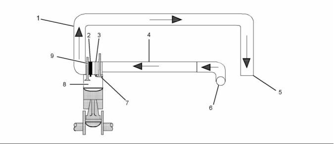
g01237037
Illustration 4
Air inlet and exhaust system
(1) Exhaust manifold
(2) Fuel injection nozzle
(3) Glow plug
(5) Exhaust outlet
(9) Inlet valve
(10) Engine cylinder
(11) Exhaust valve
(6) Turbocharger turbine wheel
(7) Turbocharger compressor wheel
(8) Air inlet
(4) Inlet manifold
The components of the air inlet and exhaust system
control the quality of air and the amount of air that is
available for combustion. The air inlet and exhaust
system consists of the following components:
Air is forced into the inlet manifold (4). Air flow from
the inlet manifold to the engine cylinders (10) is
controlled by the inlet valves (9). There is one inlet
valve and one exhaust valve (11) for each cylinder.
The inlet valve opens when the piston moves down
on the intake stroke. When the inlet valve opens,
compressed air from the inlet port is forced into the
cylinder. The complete cycle consists of four strokes:
• Air cleaner
• Turbocharger
• Inlet manifold that is integral with the cylinder head
• Cylinder head, injectors and glow plugs
• Valves and valve system components
• Piston and cylinder
• Inlet
• Compression
• Power
• Exhaust
• Exhaust manifold
On the compression stroke, the piston moves back
up the cylinder and the inlet valve (9) closes. The
air is compressed and this compression generates
more heat.
Air is drawn in through the air cleaner into the air
inlet of the turbocharger (8) by the turbocharger
compressor wheel (7). The air is compressed and
heated.
Note: If the cold starting system is operating, the
glow plugs (3) will also heat the air in the cylinder.
This document has been printed from SPI². Not for Resale
![]()
![]()
10
KENR6912
Systems Operation Section
Just before the piston reaches the TC position, fuel is
injected into the cylinder via the fuel injection nozzle
(2). The air/fuel mixture ignites. The ignition of the
gases initiates the power stroke. Both the inlet and
the exhaust valves are closed and the expanding
gases force the piston downward toward the bottom
center (BC) position .
From the BC position, the piston moves upward. This
initiates the exhaust stroke. The exhaust valve (11)
opens. The exhaust gases are forced through the
open exhaust valve into the exhaust manifold (1).
Exhaust gases from exhaust manifold (1) enter the
turbine side of the turbocharger in order to turn
turbocharger turbine wheel (6). The turbocharger
turbine wheel is connected to the shaft that drives the
turbocharger compressor wheel (7). Exhaust gases
from the turbocharger, pass through the exhaust
outlet (5), and an exhaust pipe and a silencer.
Naturally Aspirated Engines
g01237212
Illustration 5
Air inlet and exhaust system
(1) Exhaust manifold
(2) Fuel injection nozzle
(3) Glow plug
(4) Inlet manifold
(5) Exhaust outlet
(6) Air inlet
(7) Inlet valve
(8) Engine cylinder
(9) Exhaust valve
The components of the air inlet and exhaust system
control the quality of air and the amount of air that is
available for combustion. The air inlet and exhaust
system consists of the following components:
• Valves and valve system components
• Piston and cylinder
• Exhaust manifold
• Air cleaner
• Inlet manifold
• Cylinder head, injectors and glow plugs
This document has been printed from SPI². Not for Resale
![]()
![]()
KENR6912
11
Systems Operation Section
Air is drawn in through the air cleaner into the air inlet
(6) of the inlet manifold (4). Air flow from the inlet
manifold to the engine cylinders (8) is controlled by
the inlet valves (7). There is one inlet valve and one
exhaust valve (9) for each cylinder. The inlet valve
opens when the piston moves down on the intake
stroke. When the inlet valve opens, air from the inlet
port is forced into the cylinder. The complete cycle
consists of four strokes:
• Engine torque is increased.
• Durability of the engine is improved.
• Emissions from the engine are reduced.
• Inlet
• Compression
• Power
• Exhaust
On the compression stroke, the piston moves back
up the cylinder and the inlet valve (7) closes. The
air is compressed and this compression generates
more heat.
Note: If the cold starting system is operating, the
glow plugs (3) will also heat the air in the cylinder.
Just before the piston reaches the TC position, fuel is
injected into the cylinder via the fuel injection nozzle
(2). The air/fuel mixture ignites. The ignition of the
gases initiates the power stroke. Both the inlet and
the exhaust valves are closed and the expanding
gases force the piston downward toward the bottom
center (BC) position .
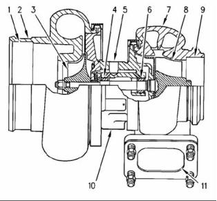
g01263770
Illustration 6
Typical example
Components of a turbocharger (typical example)
(1) Air inlet
(2) Compressor housing
(3) Turbocharger compressor wheel
(4) Bearing
(5) Oil inlet port
(6) Bearing
From the BC position, the piston moves upward. This
initiates the exhaust stroke. The exhaust valve (9)
opens. The exhaust gases are forced through the
open exhaust valve into the exhaust manifold (1).
(7) Turbine housing
(8) Turbocharger turbine wheel
(9) Exhaust outlet
(10) Oil outlet port
(11) Exhaust inlet
Exhaust gases from exhaust manifold (1), pass
through exhaust outlet (5), and an exhaust pipe and
a silencer.
A turbocharger is installed between the exhaust and
inlet manifolds. The turbocharger is driven by exhaust
gases which flow through the exhaust inlet (11). The
energy of the exhaust gas turns the turbine wheel
(8). Then, the exhaust gas flows out of the turbine
housing (7) through the exhaust outlet (9).
Turbocharger
Note: The turbocharger is not serviceable.
The turbocharger turbine wheel and the turbocharger
compressor wheel (3) are installed on the same shaft.
Therefore, the turbocharger turbine wheel and the
turbocharger compressor wheel rotate at the same
rpm. The turbocharger compressor wheel is enclosed
by the compressor housing (2). The turbocharger
compressor wheel compresses the air that is drawn
in from the air intake (1). The air flows into the engine
cylinders through the inlet valves of the cylinders.
A turbocharger increases the temperature and the
density of the air that is sent to the engine cylinder.
This condition causes a lower temperature of ignition
to develop earlier in the compression stroke. The
compression stroke is also timed in a more accurate
way with the fuel injection. Surplus air lowers the
temperature of combustion. This surplus air also
provides internal cooling.
A turbocharger improves the following aspects of
engine performance:
The oil from the main gallery of the cylinder block
flows through the oil inlet port (5) in order to
lubricate the turbocharger bearings (4) and (6). The
pressurized oil passes through the bearing housing
of the turbocharger. The oil is returned through the oil
outlet port (10) to the oil pan.
• Power output is increased.
• Fuel efficiency is improved.
This document has been printed from SPI². Not for Resale
![]()
![]()
12
KENR6912
Systems Operation Section
The turbocharger has a wastegate. The wastegate is
controlled by the boost pressure. This allows some
of the exhaust to bypass the turbocharger at higher
engine speeds. The wastegate is a type of valve
that automatically opens at a preset level of boost
pressure in order to allow exhaust gas to flow around
the turbine. The wastegate allows the design of the
turbocharger to be more effective at lower engine
speeds.
The wastegate is controlled by a diaphragm. One
side of this diaphragm is open to the atmosphere.
The other side of this diaphragm is open to the
manifold pressure.
Cylinder Head And Valves
The valves and the valve mechanism control the
flow of the air and the exhaust gases in the cylinder
during engine operation. The cylinder head assembly
has two valves for each cylinder. Each valve has one
valve spring. The ports for the inlet valves are on
the left side of the cylinder head. The ports for the
exhaust valves are on the right side of the cylinder
head. Steel valve seat inserts are installed in the
cylinder head for both the inlet and the exhaust
valves. The valve seat inserts can be replaced.
The valves are installed in valve guides. The valve
guides can be replaced. The stem of the exhaust
valve is shaped in order to prevent the seizure of the
valve. The seizure of a valve can be caused by a
buildup of carbon under the head of the valve.
The inlet and the exhaust valves are opened and
closed by the rotation and movement of the following
components:
• Crankshaft
• Camshaft
• Valve lifters
• Pushrods
• Rocker arms
• Valve springs
The camshaft gear is driven by the crankshaft gear.
The camshaft and the crankshaft are timed together.
When the camshaft turns, the valve lifters and the
pushrods are moved up and down. The pushrods
move the rocker arms. The movement of the rocker
arms open the valves. The opening and closing of
the valves is timed with the firing sequence of the
engine. The valve springs push the valves back to
the closed position.
This document has been printed from SPI². Not for Resale
![]()
KENR6912
13
Systems Operation Section
i02876572
Lubrication System
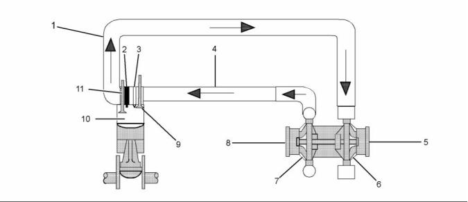
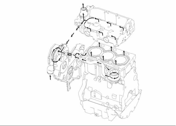
g01399859
Illustration 7
Flow diagram of the lubrication system for the 1103D engine
(1) Rocker shaft
(2) Camshaft journal
(3) Oil cooler
(5) Rod bearing journal
(6) Filter head
(7) Oil filter
(9) Oil pump
(10) Oil pump gear
(11) Lower idler gear
(4) Oil passage
(8) Oil strainer
Lubricating oil from the oil pan flows through a
strainer and a pipe (8) to the suction side of the
engine oil pump (9). Pressure for the lubrication
system is supplied by the oil pump. The crankshaft
gear drives the lower idler gear (12). The lower idler
gear (11) drives the oil pump gear (10). The pump
has an inner rotor and an outer rotor. The axis of
rotation of the rotors are off-center relative to each
other. There is an interference fit between the inner
rotor and the drive shaft.
The inner rotor has five lobes which mesh with the six
lobes of the outer rotor. When the pump rotates, the
distance increases between the lobes of the outer
rotor and the lobes of the inner rotor in order to create
suction. When the distance decreases between the
lobes, pressure is created.
This document has been printed from SPI². Not for Resale
![]()
![]()

14
KENR6912
Systems Operation Section
The lubricating oil flows from the outlet side of the oil
pump (9) through a passage to the oil filter head (6).
The oil then flows from the oil filter head through a
passage to a oil cooler (3). The oil cooler is located
on the left side of the cylinder block.
From the oil cooler, the oil returns through a passage
to the oil filter head. The oil then flows through a
bypass valve that permits the lubrication system
to function if the oil filter becomes blocked. Under
normal conditions, the oil then flows to the oil filter (7).
The oil flows from the oil filter through a passage that
is drilled across the cylinder block to the oil gallery
(4). The oil gallery is drilled through the total length
of the left side of the cylinder block. If the oil filter is
on the right side of the engine, the oil flows through
a passage that is drilled across the cylinder block to
the pressure gallery.
Lubricating oil from the oil gallery flows through
high pressure passages to the main bearings of the
crankshaft . Then, the oil flows through the passages
in the crankshaft to the connecting rod bearing
journals (5). The pistons and the cylinder bores are
lubricated by the splash of oil and the oil mist.
Lubricating oil from the main bearings flows through
passages in the cylinder block to the journals of the
camshaft. Then, the oil flows from the second journal
of the camshaft (2) at a reduced pressure to the
cylinder head. The oil then flows through the center
of the rocker shaft (1) to the rocker arm levers. The
valve stems, the valve springs and the valve lifters
are lubricated by the splash and the oil mist.
The hub of the idler gear is lubricated by oil from the
oil gallery. The timing gears are lubricated by the
splash from the oil.
An external line from the cylinder block supplies oil to
the turbocharger. The oil then flows through a return
line to the oil pan.
Engines have piston cooling jets that are supplied
with oil from the oil gallery. The piston cooling jets
spray lubricating oil on the underside of the pistons in
order to cool the pistons.
This document has been printed from SPI². Not for Resale
![]()
KENR6912
15
Systems Operation Section
i02873641
Cooling System
g01016432
Illustration 8
Flow diagram of the cooling system for the 1103D engine
The coolant flows from the bottom of the radiator to
the centrifugal water pump. The water pump assists
in the flow of the coolant through the system. The
water pump is installed on the front of the timing
case. The water pump is gear-driven by the fuel
injection pump gear.
From the rear of the cylinder block, some of the
coolant passes into the oil cooler (if equipped). The
oil cooler is located on the left side of the cylinder
block. The coolant passes through the oil cooler
before being returned through an external line to the
inlet side of the water pump.
The water pump forces the coolant through a
passage in the front of the timing case to the water
jacket in the top left side of the cylinder block. The
coolant continues to the rear of the cylinder block.
i02873644
Basic Engine
The main flow of the coolant passes from the rear of
the cylinder block into the rear of the cylinder head.
The coolant flows forward through the cylinder head
and into the water temperature regulator housing. If
the water temperature regulator is closed, the coolant
goes directly through a bypass to the inlet side of
the water pump. If the water temperature regulator
is open, the bypass is closed and the coolant flows
to the top of the radiator.
Cylinder Block and Cylinder Head
The cylinder block for the 1103D engine has three
cylinders which are arranged in-line.
This document has been printed from SPI². Not for Resale
![]()
![]()
16
KENR6912
Systems Operation Section
Crankshaft
The cylinder block for the 1103D engine has four
main bearings which support the crankshaft. Thrust
washers on both sides of the number three main
bearing control the end play of the crankshaft.
The crankshaft changes the linear energy of the
pistons and connecting rods into rotary torque in
order to power external equipment.
A cylinder head gasket is used between the
engine block and the cylinder head in order to seal
combustion gases, water, and oil.
A gear at the front of the crankshaft drives the timing
gears. The crankshaft gear turns the idler gear which
then turns the following gears:
The engine has a cast iron cylinder head. The inlet
manifold is integral within the cylinder head. An inlet
valve and an exhaust valve for each cylinder are
controlled by a pushrod valve system. The ports for
the inlet valves are on the left side of the cylinder
head. The ports for the exhaust valves are on the
right side of the cylinder head.
• Camshaft gear
• Fuel injection pump
• Lower idler gear which turns the gear of the
lubricating oil pump
Pistons, Rings, and Connecting
Rods
Camshaft
The engine has a single camshaft. The camshaft
is driven by an idler gear in the front housing. The
camshaft uses only one bearing on the front journal.
The other journals rotate in the bore of the cylinder
block. The front bearing and the camshaft bores
in the cylinder block support the camshaft. As the
camshaft turns, the camshaft lobes move the valve
system components. The valve system components
move the inlet and exhaust valves in each cylinder.
The camshaft gear must be timed to the crankshaft
gear. The relationship between the lobes and the
camshaft gear causes the valves in each cylinder to
be opened and closed at the correct time.
The pistons have a combustion chamber in the top of
the piston in order to provide an efficient mix of fuel
and air. The piston pin is off-center in order to reduce
the noise level.
The pistons have two compression rings and an oil
control ring. The groove for the top ring has a hard
metal insert in order to reduce wear of the groove.
The skirt has a layer of graphite in order to reduce
wear.
The correct piston height is important in order to
ensure that the piston does not contact the cylinder
head. The correct piston height also ensures the
efficient combustion of fuel which is necessary in
order to conform to requirements for emissions.
i02797480
Electrical System
Engines are equipped with connecting rods that have
bearing caps that are fracture split. The bearing caps
on fracture split connecting rods are retained with
torx screws. Connecting rods with bearing caps that
are fracture split have the following characteristics:
The electrical system is a negative ground system.
The charging circuit operates when the engine
is running. The alternator in the charging circuit
produces direct current for the electrical system.
• Higher integrity for the rod
• The splitting produces an accurately matched
surface on each side for improved strength.
• Modern design
The connecting rod is matched to each cylinder.
The piston height is controlled by the length of the
connecting rod. Six different lengths of connecting
rods are available in order to attain the correct piston
height.
This document has been printed from SPI². Not for Resale
![]()
KENR6912
17
Systems Operation Section
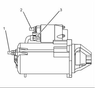
Starting Motor
Alternator
g00303424
g01216877
Illustration 10
Illustration 9
(1) Typical view of a shaft for mounting the pulley
Typical view of a 12 Volt Starting Motor
(1) Terminal for connection of the ground cable
(2) Terminal 30 for connection of the battery cable
(3) Terminal 50 for connection of the ignition switch
The alternator produces the following electrical
output:
• Three-phase
• Full-wave
• Rectified
The starting motor turns the engine flywheel. The
rpm is high enough in order to initiate a sustained
operation of the fuel ignition in the cylinders.
The starting motor has a solenoid. When the ignition
switch is activated, voltage from the electrical system
will cause the solenoid to engage the pinion in the
flywheel ring gear of the engine. When the pinion
gear is engaged in the flywheel ring gear, the
electrical contacts in the solenoid close the circuit
between the battery and the starting motor.
The alternator is an electro-mechanical component.
The alternator is driven by a drive belt from the
crankshaft pulley. The alternator charges the storage
battery during the engine operation.
The alternator converts the mechanical energy
and the magnetic energy into electrical energy.
This conversion is done by rotating a direct current
electromagnetic field on the inside of a three-phase
stator. The electromagnetic field is generated by
electrical current flowing through a rotor. The stator
generates AC electrical power.
When the engine begins to run, the overrunning
clutch of the pinion drive prevents damage to the
armature. Damage to the armature is caused by
excessive speeds. The clutch prevents damage by
stopping the mechanical connection. However, the
pinion will stay meshed with the ring gear until the
ignition switch is released. A spring in the overrunning
clutch returns the clutch to the rest position.
The alternating current is changed to direct current
by a three-phase, full-wave rectifier. Direct current
flows to the output terminal of the alternator. The
rectifier has three exciter diodes. The direct current
is used for the charging process.
A regulator is installed on the rear end of the
alternator. Two brushes conduct current through two
slip rings. The current then flows to the rotor field. A
capacitor protects the rectifier from high voltages.
The alternator is connected to the battery through
the ignition switch. Therefore, alternator excitation
occurs when the switch is in the ON position.
This document has been printed from SPI². Not for Resale
![]()
![]()
![]()
18
KENR6912
Testing and Adjusting Section
Testing and Adjusting
Section
2. Install a suitable sight gauge in the fuel return line.
When possible, install the sight gauge in a straight
section of the fuel line that is at least 304.8 mm
(12 inches) long. Do not install the sight gauge
near the following devices that create turbulence:
Fuel System
• Elbows
• Relief valves
• Check valves
i02797486
Fuel System - Inspect
Observe the fuel flow during engine cranking.
Look for air bubbles in the fuel. If there is no fuel
that is present in the sight gauge, prime the fuel
system. Refer to Systems Operation, Testing
and Adjusting, “Fuel System - Prime” for more
information. If the engine starts, check for air in
the fuel at varying engine speeds. When possible,
operate the engine under the conditions which
have been suspect.
A fault with the components that send fuel to the
engine can cause low fuel pressure. This can
decrease engine performance.
1. Check the fuel level in the fuel tank. , Ensure that
the vent in the fuel cap is not filled with dirt.
2. Check all fuel lines for fuel leakage. The fuel lines
must be free from restrictions and faulty bends.
Verify that the fuel return line is not collapsed.
3. Inspect the fuel filter for excess contamination. If
necessary, install a new fuel filter. Determine the
source of the contamination. Make the necessary
repairs.
4. Service the primary fuel filter (if equipped).
5. Remove any air that may be in the fuel system.
Refer to Systems Operation, Testing and
Adjusting, “Fuel System - Prime”.
i02873659
Air in Fuel - Test
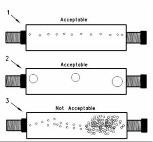
g00578151
Illustration 11
This procedure checks for air in the fuel system. This
procedure also assists in finding the source of the air.
Sight Gauge
(1) A steady stream of small bubbles with a diameter of
approximately 1.60 mm (0.063 inch) is an acceptable amount
of air in the fuel.
(2) Bubbles with a diameter of approximately 6.35 mm (0.250 inch)
are also acceptable if there is two seconds to three seconds
intervals between bubbles.
1. Examine the fuel system for leaks. Ensure that
the fuel line fittings are properly tightened. Check
the fuel level in the fuel tank. Air can enter the
fuel system on the suction side between the fuel
transfer pump and the fuel tank.
(3) Excessive air bubbles in the fuel are not acceptable.
Work carefully around an engine that is running.
Engine parts that are hot, or parts that are moving,
can cause personal injury.
This document has been printed from SPI². Not for Resale
![]()
![]()
![]()
![]()
KENR6912
19
Testing and Adjusting Section
3. If excessive air is seen in the sight gauge in the
fuel return line, install a second sight gauge at the
inlet to the fuel transfer pump. If a second sight
gauge is not available, move the sight gauge from
the fuel return line and install the sight gauge at
the inlet to the fuel transfer pump. Observe the fuel
flow during engine cranking. Look for air bubbles
in the fuel. If there is no fuel that is present in
the sight gauge, prime the fuel system. Refer
to Systems Operation, Testing and Adjusting,
“Fuel System - Prime” for more information. If the
engine starts, check for air in the fuel at varying
engine speeds.
i02873757
Finding Top Center Position
for No. 1 Piston
Table 1
Required Tools
Tool
A
Part Number
27610211
27610212
Part Description
Crankshaft Timing Pin
Camshaft Timing Pin
Qty
1
B
1
If excessive air is not seen at the inlet to the
fuel transfer pump, the air is entering the system
after the fuel transfer pump. Refer to Systems
Operation, Testing and Adjusting, “Fuel System -
Prime”.
If excessive air is seen at the inlet to the fuel
transfer pump, air is entering through the suction
side of the fuel system.
To avoid personal injury, always wear eye and face
protection when using pressurized air.
NOTICE
To avoid damage, do not use more than 55 kPa (8 psi)
to pressurize the fuel tank.
4. Pressurize the fuel tank to 35 kPa (5 psi). Do
not use more than 55 kPa (8 psi) in order to
avoid damage to the fuel tank. Check for leaks
in the fuel lines between the fuel tank and
the fuel transfer pump. Repair any leaks that
are found. Check the fuel pressure in order to
ensure that the fuel transfer pump is operating
properly. For information about checking the fuel
pressure, Refer to Systems Operation, Testing
and Adjusting, “Fuel System Pressure - Test”.
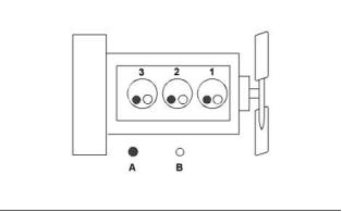
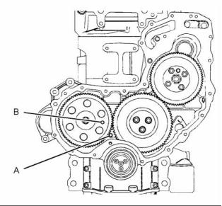
g01431408
Illustration 12
Typical example
(A) Hole for crankshaft timing pin
(B) Hole for camshaft timing pin
1. Remove the valve mechanism cover. Refer to
Disassembly and Assembly, “Valve Mechanism
Cover - Remove and Install”.
2. Remove the glow plugs. Refer to Disassembly
5. If the source of the air is not found, disconnect
the supply line from the fuel tank and connect an
external fuel supply to the inlet of the fuel transfer
pump. If this corrects the problem, repair the fuel
tank or the stand pipe in the fuel tank.
and Assembly, “Glow Plugs - Remove and Install”.
3. Remove the cover for the front housing. Refer
to Disassembly and Assembly, “Front Cover -
Remove and Install”.
Note: Tooling (A) can be inserted with the crankshaft
pulley still on the engine.
4. Rotate the crankshaft in the normal direction of the
engine until Tooling (B) can be inserted through
the camshaft gear and into the timing case.
Note: The camshaft gear can rotate a small amount
when Tooling (B) is installed.
This document has been printed from SPI². Not for Resale
![]()
![]()
![]()
![]()
![]()
![]()
20
KENR6912
Testing and Adjusting Section
5. Carefully rotate the crankshaft in the normal
direction of the engine in order to align the hole in
the crankshaft with the hole in the timing case and
the cylinder block. Insert Tooling (A) fully into the
hole in the crankshaft web.
i02876576
Fuel Injection Pump Timing -
Adjust
Note: When Tooling (A) is inserted, number one
piston will be at top center.
Delphi DP210 and DP310 Fuel
Injection Pumps
6. Remove the Tooling (B) from the camshaft gear
and Tooling (A) from the crankshaft web.
The Delphi DP210 and DP310 fuel injection
pumps must be serviced by an authorized Delphi
technician. For repair information, contact your
Perkins distributor. The internal adjustment for the
pump timing is tamper proof. High idle and low idle
are factory set. High Idle adjustments can not be
made to the fuel pump.
7. Install the cover for the front housing. Refer
to Disassembly and Assembly, “Front Cover -
Remove and Install”.
8. Install the glow plugs. Refer to Disassembly and
Assembly, “Glow Plugs - Remove and Install”.
9. Install the valve mechanism cover. Refer to
Disassembly and Assembly, “Valve Mechanism
Cover - Remove and Install”.
i02563386
Fuel Quality - Test
i02876575
Fuel Injection Pump Timing -
Check
Note: Refer to Systems Operation, “Cleanliness
of Fuel System Components” for detailed
information on the standards of cleanliness that
must be observed during ALL work on the fuel
system.
Delphi DP210 and DP310 Fuel
Injection Pumps
Ensure that all adjustments and repairs are performed
by authorized personnel that have had the correct
training.
Note: The Delphi DP210 and DP310 fuel injection
pump timing cannot be checked. If you suspect that
the fuel injection pump timing is incorrect, contact
your Perkins distributor for further information.
Use the following procedure to test for problems
regarding fuel quality:
1. Determine if water and/or contaminants are
present in the fuel. Check the water separator (if
equipped). If a water separator is not present,
proceed to Step 2. Drain the water separator, if
necessary. A full fuel tank minimizes the potential
for overnight condensation.
Delphi DP210 and DP310 fuel injection pumps must
be serviced by an authorized Delphi technician. For
repair information, contact your Perkins distributor.
The internal adjustment for the pump timing is tamper
proof. High idle and low idle are factory set. High idle
adjustments cannot be made to the fuel pump.
Note: A water separator can appear to be full of fuel
when the water separator is actually full of water.
2. Determine if contaminants are present in the
fuel. Remove a sample of fuel from the bottom
of the fuel tank. Visually inspect the fuel sample
for contaminants. The color of the fuel is not
necessarily an indication of fuel quality. However,
fuel that is black, brown, and/or similar to sludge
can be an indication of the growth of bacteria or
oil contamination. In cold temperatures, cloudy
fuel indicates that the fuel may not be suitable for
operating conditions.
This document has been printed from SPI². Not for Resale
![]()
KENR6912
21
Testing and Adjusting Section
Refer to Operation and Maintenance Manual,
i02797519
“Fuel Recommendations” for more information.
Fuel System Pressure - Test
3. If fuel quality is still suspected as a possible
cause to problems regarding engine performance,
disconnect the fuel inlet line, and temporarily
operate the engine from a separate source of
fuel that is known to be good. This will determine
if the problem is caused by fuel quality. If fuel
quality is determined to be the problem, drain the
fuel system and replace the fuel filters. Engine
performance can be affected by the following
characteristics:
• Cetane number of the fuel
• Air in the fuel
• Other fuel characteristics
i02797518
Fuel System - Prime
If air enters the fuel system, the air must be purged
before the engine can be started. Air can enter the
fuel system when the following events occur:
• The fuel tank is empty or the tank has been partially
drained during normal operation.
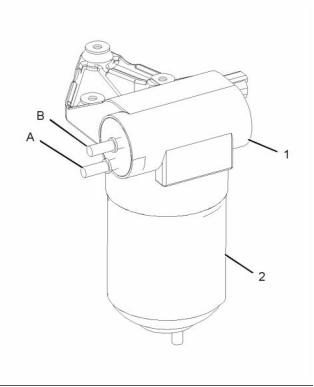
g01235017
Illustration 13
• The low pressure fuel lines are disconnected.
(A and B) Fuel outlet
(1) Fuel transfer pump
(2) Fuel filter
• A leak exists in the low pressure fuel system during
engine operation.
The pressure test measures the output pressure of
the fuel transfer pump. Low fuel pressure and starting
difficulty may be indications of faults with the fuel
priming pump.
• The fuel filter or the fuel pump is replaced.
• The high pressure fuel lines are disconnected.
Delphi DP210 and DP310
Check the Function of the Fuel
Transfer Pump
The Delphi DP210 and DP310 fuel injection
pumps will eliminate the air from the fuel system
automatically. Position the starting switch to the RUN
position for three minutes. Air in the fuel and the fuel
lines will be purged from the system.
1. Make a note of the location of the fuel lines from
the fuel transfer pump. Remove the two lines from
fuel outlets (A) and (B).
2. Connect two suitable lengths of 5/16 inch rubber
hose to fuel outlets (A) and (B). Place the hoses
into a suitable container that is capable of holding
3 L (3.17 qt) of fuel.
3. Energize the fuel transfer pump until a constant
flow of fuel is running from the outlet for the supply
for the fuel injection pump.
Note: The flow from fuel outlet (B) for the return to
the fuel tank will have a slower flow rate.
This document has been printed from SPI². Not for Resale
![]()
![]()
22
KENR6912
Testing and Adjusting Section
4. Use a suitable tool in order to measure the
combined flow of both outlets with a stopwatch.
Fuel flow should be a minimum of 2 L/min
(0.53 US gpm).
5. If the combined flow is less than 2 L/min
(0.53 US gpm), replace the pump.
6. Reconnect the outlet lines in the correct positions.
7. Start the engine and check for any leakage of fuel
or air from the fuel lines.
Check the Function of the Pressure
Regulator
1. Remove the fuel line from fuel outlet (A) for the
supply to the fuel injection pump.
2. Install a suitable pipe with a tap for a pressure
gauge. Connect a 0 to 80 kPa (0 to 12 psi)
pressure gauge.
Note: One end of the pipe must be blanked.
3. Energize the fuel transfer pump for two minutes in
order to remove any trapped air.
4. Record the pressure reading at high idle. The
minimum pressure reading should be the following
values:
All Fuel Injection Pumps
Low idle ................................. 25 kPa (3.6 psi)
High idle ................................ 25 kPa (3.6 psi)
Note: The maximum pressure for the fuel injection
pump at idle speed or rated speed is 75 kPa
(10.9 psi).
5. Reconnect the fuel line. Energize the fuel transfer
pump for two minutes in order to remove any
trapped air.
Check for the following issues if the pressures are
outside of the above specifications.
• All electrical connections are installed correctly.
• There are no leaks in the fuel lines or connections.
• The O-ring on the fuel filter housing (2) does not
leak.
This document has been printed from SPI². Not for Resale
![]()
KENR6912
23
Testing and Adjusting Section
Air Inlet and Exhaust
System
Hot engine components can cause injury from
burns. Before performing maintenance on the
engine, allow the engine and the components to
cool.
i02797521
Air Inlet and Exhaust System
- Inspect
NOTICE
Keep all parts clean from contaminants.
Contaminants may cause rapid wear and shortened
component life.
A general visual inspection should be made to the air
inlet and exhaust system. Make sure that there are
no signs of leaks in the system.
There will be a reduction in the performance of the
engine if there is a restriction in the air inlet system or
the exhaust system.
Hot engine components can cause injury from
burns. Before performing maintenance on the
engine, allow the engine and the components to
cool.
Making contact with a running engine can cause
burns from hot parts and can cause injury from
rotating parts.
When working on an engine that is running, avoid
contact with hot parts and rotating parts.
1. Inspect the engine air cleaner inlet and ducting
in order to ensure that the passageway is not
blocked or collapsed.
2. Inspect the engine air cleaner element. Replace a
dirty element with a clean element.
3. Check for dirt tracks on the clean side of the
engine air cleaner element. If dirt tracks are
observed, contaminants are flowing past the
element.
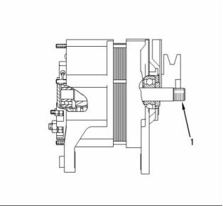
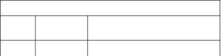
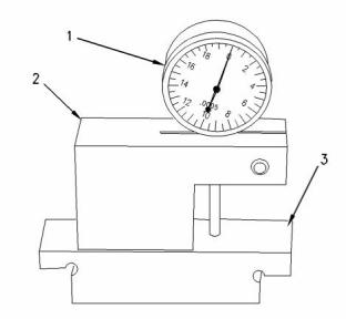
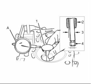
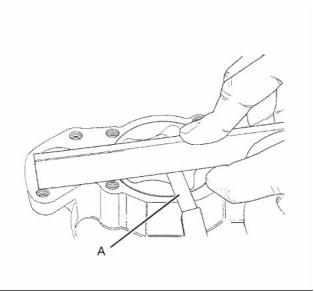
g01401677
Illustration 14
Typical example
i02875196
Note: The turbocharger is a nonserviceable item.
The pressure for the wastegate can be checked, but
not adjusted.
Wastegate - Test
1. Install Tooling (A). Tooling (A) is shown in
illustration 14. Align the dial gauge on Tooling (A)
to the actuator rod (1).
Table 2
Required Tools
Part
2. Remove the air hose to the actuator. Install a
suitable air line (2) that can be adjusted in order to
give the correct pressure.
Tool
Part Description
Qty
Number
A
21825617
Dial Gauge
1
This document has been printed from SPI². Not for Resale
![]()
![]()
![]()
![]()
![]()
![]()
![]()
![]()
![]()
![]()
24
KENR6912
Testing and Adjusting Section
3. Slowly apply air pressure to the wastegate so
that the actuator rod moves 1.0 mm (0.039 inch).
The air pressure should be within 107 to 117 kPa
(15.5 to 17.0 psi). Ensure that the dial indicator
returns to zero when the air pressure is released.
Repeat the test several times. This will ensure that
an accurate reading is obtained.
i02875199
Engine Crankcase Pressure
(Blowby) - Test
Damaged pistons or rings can cause too much
pressure in the crankcase. This condition will cause
the engine to run rough. There will be more than the
normal amount of fumes (blowby) rising from the
crankcase breather. The breather can then become
restricted in a very short time, causing oil leakage
at gaskets and seals that would not normally have
leakage. Blowby can also be caused by worn valve
guides or by a failed turbocharger seal.
Note: Do not exceed 205 kPa (30 psi) in order
to check the actuator. Refer to Specification,
“Turbocharger” for information on the correct
pressure setting for your actuator.
4. For more information on installing a new
turbocharger, contact a Perkins dealer.
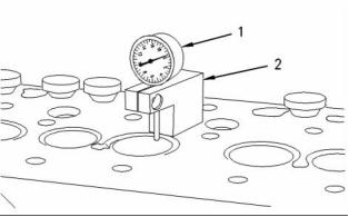
i02875197
Exhaust Temperature - Test
Measure the Exhaust Temperature
When the engine runs at low idle, the temperature of
an exhaust manifold port can indicate the condition
of a fuel injection nozzle.
A low temperature indicates that no fuel is flowing to
the cylinder. An inoperative fuel injection nozzle or
a problem with the fuel injection pump could cause
this low temperature.
g00286269
Illustration 15
Typical air gauge
A very high temperature can indicate that too much
fuel is flowing to the cylinder. A malfunctioning
fuel injection nozzle could cause this very high
temperature.
Use a suitable air gauge in order to check the amount
of blowby.
i02797667
Use a suitable laser infrared thermometer in order to
check the exhaust temperature at the exhaust outlet
for each cylinder.
Compression - Test
Compare the temperature readings for each exhaust
outlet. Investigate any difference in the temperature
readings.
The cylinder compression test should only be used
in order to compare the cylinders of an engine.
The pressure in the cylinder should be between
300 to 500 kPa (43.5120 to 72.5200 psi). If one or
more cylinders vary by more than 350 kPa (51 psi),
the cylinder and related components may need to
be repaired.
A compression test should not be the only method
which is used to determine the condition of an engine.
Other tests should also be conducted in order to
determine if the adjustment or the replacement of
components is required.
Before the performance of the compression test,
make sure that the following conditions exist:
This document has been printed from SPI². Not for Resale
![]()
![]()
KENR6912
25
Testing and Adjusting Section
• The battery is in good condition.
• The battery is fully charged.
Not enough valve lash can be the cause of rapid
wear of the camshaft and valve lifters. Not enough
valve lash can indicate that the seats for the valves
are worn.
• The starting motor operates correctly.
• The valve lash is set correctly.
• All fuel injectors are removed.
• The fuel supply is disconnected.
Valves become worn due to the following causes:
• Fuel injectors that operate incorrectly
• Excessive dirt and oil are present on the filters for
the inlet air.
1. Install a gauge for measuring the cylinder
compression in the hole for a fuel injector.
• Incorrect fuel settings on the fuel injection pump.
• The load capacity of the engine is frequently
exceeded.
2. Operate the starting motor in order to turn the
engine. Record the maximum pressure which is
indicated on the compression gauge.
Too much valve lash can cause broken valve stems,
springs, and spring retainers. Too much valve lash
can be an indication of the following problems:
3. Repeat Steps 1 and 2 for all cylinders.
• Worn camshaft and valve lifters
• Worn rocker arms
i02875200
Engine Valve Lash -
Inspect/Adjust
• Bent pushrods
• Broken socket on the upper end of a pushrod
• Loose adjustment screw for the valve lash
Table 3
Required Tools
If the camshaft and the valve lifters show rapid wear,
look for fuel in the lubrication oil or dirty lubrication
oil as a possible cause.
Tool
Part Number
Part Description
Qty
A
26710298
Angled feeler gauge
1
The valve lash is measured between the top of the
valve stem and the rocker arm lever.
To prevent possible injury, do not use the starter
to turn the flywheel.
Note: An adjustment is not necessary if the
measurement of the valve lash is in the acceptable
range. Inspect the valve lash while the engine is
stopped. The temperature of the engine does not
change the valve lash setting.
Hot engine components can cause burns. Allow
additional time for the engine to cool before mea-
suring valve clearance.
Note: When the following procedures are performed,
the front housing must be installed.
Valve Lash Setting
Table 4
Inlet Valves
Exhaust Valves
Valve Lash
0.2 ± 0.05 mm
(0.008 ± 0.002
inch)
0.45 ± 0.05 mm
(0.018 ± 0.002 inch)
Refer to Systems Operation, Testing and Adjusting,
“Engine Design” for the location of the cylinder valves.
If the valve lash requires adjustment several times
in a short period of time, excessive wear exists in
a different part of the engine. Find the problem and
make necessary repairs in order to prevent more
damage to the engine.
This document has been printed from SPI². Not for Resale
![]()
![]()
![]()
26
KENR6912
Testing and Adjusting Section
2. Rotate the crankshaft in a clockwise direction that
is viewed from the front of the engine. When the
inlet valve of the No 1 cylinder has opened and
the exhaust valve of the No 1 cylinder has not
completely closed measure the valve lash of the
inlet valve of No 2 cylinder and the exhaust valve
of No 3 cylinder. If necessary, make adjustment.
a. Lightly tap the rocker arm at the top of the
adjustment screw with a soft mallet. This
will ensure that the lifter seats against the
camshaft.
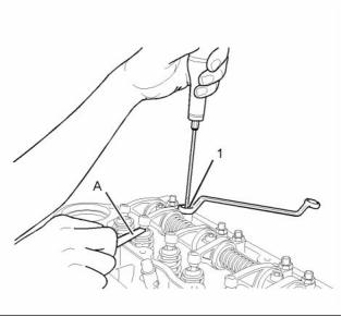
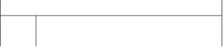
b. Loosen the valve adjustment screw locknut
that is on adjustment screw (1).
c. Place Tooling (A) between the rocker arm and
the valve. Turn adjustment screw (1) while the
valve adjustment screw locknut is being held
from turning. Adjust the valve lash until the
correct specification is achieved.
g01227408
Illustration 16
d. Tighten the adjustment locknut to a torque of
27 N·m (20 lb ft). Do not allow the adjustment
screw to turn while you are tightening the
adjustment locknut. Recheck the valve lash
after tightening the adjustment locknut.
Setting the valve lash
(1) Adjustment screw
(A) Angled Feeler gauge
Valve Lash Adjustment
3. Rotate the crankshaft in a clockwise direction that
is viewed from the front of the engine. When the
inlet valve of the No 2 cylinder has opened and
the exhaust valve of the No 2 cylinder has not
completely closed measure the valve lash of the
inlet valve for No 3 cylinder and the exhaust valve
for No 1 cylinder.
Accidental engine starting can cause injury or
death to personnel.
To prevent accidental engine starting, turn the ig-
nition switch to the OFF position, place a do not
operate tag at the ignition switch location and dis-
connect and tape the electrical connection to the
stop solenoid that is located on the fuel injection
pump.
If adjustment is necessary, refer to Step 2.
4. Rotate the crankshaft in a clockwise direction that
is viewed from the front of the engine. When the
inlet valve of the No 3 cylinder has opened and
the exhaust valve of the No 3 cylinder has not
completely closed measure the valve lash of the
inlet valve for No 1 cylinder and the exhaust valve
for No 2 cylinder.
Table 5
Inlet Valves
Exhaust Valves
Valve Lash
Firing Order
0.2 ± 0.05 mm
(0.008 ± 0.002 (0.018 ± 0.0020 inch)
inch)
0.45 ± 0.05 mm
If adjustment is necessary, refer to Step 2.
5. Install the valve mechanism cover. Refer to
Disassembly and Assembly, “Valve Mechanism
Cover - Remove and Install”.
1-2-3
(1)
(1) The No. 1 Cylinder is at the front of the engine.
1. Remove the valve mechanism cover. Refer to
Disassembly and Assembly, “Valve Mechanism
Cover - Remove and Install”.
This document has been printed from SPI². Not for Resale
![]()
![]()
![]()
![]()
KENR6912
27
Testing and Adjusting Section
i02875207
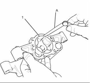
2. Position gauge body (2) and dial indicator (1) in
order to measure the valve depth. Measure the
depth of the inlet valve and the exhaust valve
before the valve springs are removed.
Valve Depth - Inspect
Refer to Specifications, “Cylinder Head Valves”
for the minimum, the maximum, and the service
wear limits for the valve depth below the cylinder
head face.
Table 6
Required Tools
Part
Tool
Part Name
Qty
Number
If the valve depth below the cylinder head face
exceeds the service limit, use a new valve to
check the valve depth. If the valve depth still
exceeds the service limit, renew the cylinder head
or renew the valve seat inserts. If the valve depth
is within the service limit, renew the valves.
A
GE50002
Liner Projection Tool
1
3. Inspect the valves for cracks and other damage.
Check the valve stems for wear. Check that the
valve springs are the correct length under the
test force. Refer to Specifications, “Cylinder Head
Valves” for the dimensions and tolerances of the
valves and valve springs.
i02875210
Valve Guide - Inspect
Table 7
Required Tools
Tool
Part
Number
Part Name
Qty
g00323908
Illustration 17
Liner Projection Tool
A
21825617
Dial Gauge
1
(1) Dial indicator
(2) Gauge body
(3) Gauge block
Perform this test in order to determine if a valve guide
should be replaced.
1. Use Tooling (A) in order to check the depths of
the inlet valves and the exhaust valves below the
face of the cylinder head. Use gauge block (3) to
zero dial indicator (1).
g00323909
Illustration 18
Measurement of the valve depth
(1) Dial indicator
(2) Gauge body
This document has been printed from SPI². Not for Resale
![]()
![]()
![]()
![]()
28
KENR6912
Testing and Adjusting Section
Refer to Specifications, “Cylinder Head Valves” for
the maximum clearance of the valve in the valve
guide.
g01235205
Illustration 19
(A) Dial gauge
(1) Valve head
(2) Valve guide
(3) Radial movement of the valve in the valve guide
(4) Valve stem
1. Place a new valve in the valve guide.
2. Place Tooling A with the magnetic base on the
face of the cylinder head.
3. Lift the edge of the valve head (1) to a distance
of 15.0 mm (0.60 inch).
4. Move the valve in a radial direction away from
Tooling (A). Make sure that the valve moves away
from Tooling (A) as far as possible. Position the
contact point of Tooling (A) on the edge of the
valve head (1). Set the position of the needle of
Tooling (A) to zero.
5. Move the valve in a radial direction toward Tooling
(A) as near as possible. Note the distance of
movement which is indicated on Tooling (A). If the
distance is greater than the maximum clearance
of the valve in the valve guide, replace the valve
guide.
When new valve guides are installed, new valves
and new valve seat inserts must be installed.
Valve guides and valve seat inserts are supplied
as an unfinished part. The unfinished valve guides
and unfinished valve seat inserts are installed in
the cylinder head. Then, the valve guides and
valve inserts are cut and reamed in one operation
with special tooling.
This document has been printed from SPI². Not for Resale
![]()
![]()
KENR6912
29
Testing and Adjusting Section
Lubrication System
Engine Oil Pressure - Test
Low Oil Pressure
i02875224
Engine Oil Pump - Inspect
i02875215
Table 8
Required Tools
Tool
Part Number
Part Description
Qty
A
CVT0014
Feeler gauge
1
The following conditions will cause low oil pressure.
• The oil level is low in the crankcase.
If any part of the oil pump is worn enough in order to
affect the performance of the oil pump, the oil pump
must be replaced.
• A restriction exists on the oil suction screen.
• Connections in the oil lines are leaking.
Perform the following procedures in order to inspect
the oil pump for clearances and torques.
• The connecting rod or the main bearings are worn.
• The rotors in the oil pump are worn.
Refer to Specifications, “Engine Oil Pump”.
1. Remove the oil pump from the engine. Refer to
Disassembly and Assembly, “Engine Oil Pump -
Remove”. Remove the cover of the oil pump.
• The oil pressure relief valve is operating incorrectly.
A worn oil pressure relief valve can allow oil to leak
through the valve which lowers the oil pressure.
Refer to Specifications, “Engine Oil Relief Valve” for
the correct operating pressure and other information.
2. Remove the outer rotor. Clean all of the parts.
Look for cracks in the metal or other damage.
When an engine that is turbocharged runs at the
normal temperature for operation and at high idle, the
oil pressure must be a minimum of 280 kPa (40 psi).
A lower pressure is normal at low idle.
Use a suitable pressure gauge in order to test the
pressure of the lubrication system.
High Oil Pressure
High oil pressure can be caused by the following
conditions.
• The spring for the oil pressure relief valve is
installed incorrectly.
• The plunger for the oil pressure relief valve
becomes jammed in the closed position.
g01235471
Illustration 20
• Excessive sludge exists in the oil which makes the
viscosity of the oil too high.
Clearance for the outer rotor body
(1) Outer rotor to the body
(A) Feeler gauge
3. Install the outer rotor. Place Tooling (A) between
the outer body and the outer rotor in order to
measure the clearance of the outer rotor to the
body (1). Refer to Specifications, “Engine Oil
Pump”.
This document has been printed from SPI². Not for Resale
![]()
![]()
30
KENR6912
Testing and Adjusting Section
6. Clean the top face of the oil pump and the bottom
face of the cover. Install the cover on the oil
pump. Install the oil pump on the engine. Refer to
Disassembly and Assembly, “Engine Oil Pump -
Install”.
i02801063
Excessive Bearing Wear -
Inspect
When some components of the engine show bearing
wear in a short time, the cause can be a restriction in
an oil passage.
An engine oil pressure indicator may show that there
is enough oil pressure, but a component is worn
due to a lack of lubrication. In such a case, look at
the passage for the oil supply to the component.
A restriction in an oil supply passage will not allow
enough lubrication to reach a component. This will
result in early wear.
g01235472
Illustration 21
Clearance for the inner rotor
(2) Inner rotor to the outer rotor
(A) Feeler gauge
4. Place Tooling (A) between the inner rotor (2) and
the outer rotor in order to measure the clearance.
i02801065
Excessive Engine Oil
Consumption - Inspect
Engine Oil Leaks on the Outside of
the Engine
Check for leakage at the seals at each end of the
crankshaft. Look for leakage at the gasket for the
engine oil pan and all lubrication system connections.
Look for any engine oil that may be leaking from
the crankcase breather. This can be caused by
combustion gas leakage around the pistons. A dirty
crankcase breather will cause high pressure in the
crankcase. A dirty crankcase breather will cause the
gaskets and the seals to leak.
Engine Oil Leaks into the
Combustion Area of the Cylinders
g01235624
Illustration 22
End play measurement for the rotor
(A) Feeler gauge
Engine oil that is leaking into the combustion area of
the cylinders can be the cause of blue smoke. There
are several possible ways for engine oil to leak into
the combustion area of the cylinders:
5. Measure the end play of the rotor with a straight
edge and Tooling (A). Refer to Specifications,
“Engine Oil Pump”.
• Failed valve stem seals
• Leaks between worn valve guides and valve stems
This document has been printed from SPI². Not for Resale
![]()
![]()
![]()
KENR6912
31
Testing and Adjusting Section
• Worn components or damaged components
(pistons, piston rings, or dirty return holes for the
engine oil)
• Incorrect installation of the compression ring and/or
the intermediate ring
• Leaks past the seal rings in the turbocharger shaft
• Overfilling of the crankcase
• Wrong dipstick or guide tube
• Sustained operation at light loads
Excessive consumption of engine oil can also
result if engine oil with the wrong viscosity is used.
Engine oil with a thin viscosity can be caused by fuel
leakage into the crankcase or by increased engine
temperature.
i02801067
Increased Engine Oil
Temperature - Inspect
Look for a restriction in the oil passages of the oil
cooler. The oil temperature may be higher than
normal when the engine is operating. In such a
case, the oil cooler may have a restriction. High oil
temperature can be a cause of low oil pressure.
Determine if the oil cooler bypass valve is held in the
open position. This condition will allow the oil to pass
through the valve instead of the oil cooler. The oil
temperature will increase.
This document has been printed from SPI². Not for Resale
![]()
32
KENR6912
Testing and Adjusting Section
Cooling System
6. Check the filler cap. A pressure drop in the cooling
system can cause the boiling point to be lower.
This can cause the cooling system to boil. Refer
to Systems Operation, Testing and Adjusting,
“Cooling System - Test”.
i02801080
Cooling System - Check
(Overheating)
7. Check the cooling system hoses and clamps.
Damaged hoses with leaks can normally be
seen. Hoses that have no visual leaks can soften
during operation. The soft areas of the hose
can become kinked or crushed during operation.
These areas of the hose can cause a restriction
in the coolant flow. Hoses become soft and/or get
cracks after a period of time. The inside of a hose
can deteriorate, and the loose particles of the
hose can cause a restriction of the coolant flow.
Above normal coolant temperatures can be caused
by many conditions. Use the following procedure
to determine the cause of above normal coolant
temperatures:
1. Check the coolant level in the cooling system. If
the coolant level is too low, air will get into the
cooling system. Air in the cooling system will
cause a reduction in coolant flow and bubbles
in the coolant. Air bubbles will keep the coolant
away from the engine parts, which will prevent the
transfer of heat to the coolant. Low coolant level is
caused by leaks or incorrectly filling the expansion
tank.
8. Check for a restriction in the air inlet system. A
restriction of the air that is coming into the engine
can cause high cylinder temperatures. High
cylinder temperatures require higher than normal
temperatures in the cooling system.
9. Check for a restriction in the exhaust system.
A restriction of the air that is coming out of the
engine can cause high cylinder temperatures.
2. Check the mixture of the antifreeze. Refer to
Operation and Maintenance Manual, “Cooling
System Coolant Sample (Level 2) - Obtain”.
a. Make a visual inspection of the exhaust system.
b. Check for damage to exhaust piping. Check for
damage to the exhaust elbow. If no damage
is found, check the exhaust system for a
restriction.
3. Check for air in the cooling system. Air can enter
the cooling system in different ways. The most
common causes of air in the cooling system
are not filling the cooling system correctly and
combustion gas leakage into the cooling system.
Combustion gas can get into the system through
inside cracks, a damaged cylinder head, or a
damaged cylinder head gasket. Air in the cooling
system causes a reduction in coolant flow and
bubbles in the coolant. Air bubbles keep the
coolant away from the engine parts, which
prevents the transfer of heat to the coolant. Refer
to Systems Operation, Testing and Adjusting,
“Cooling System - Inspect”.
10. Check the water temperature regulator. A water
temperature regulator that does not open, or a
water temperature regulator that only opens part
of the way can cause overheating. Refer to Testing
and Adjusting, “Water Temperature Regulator -
Test”.
11. Check the water pump. A water pump with a
damaged impeller does not pump enough coolant
for correct engine cooling. Remove the water
pump. Refer to Disassembly and Assembly,
“Water Pump - Remove”. Inspect the water pump
impeller for damage. Refer to Disassembly and
Assembly, “Water Pump - Disassemble”.
4. Check the sending unit. In some conditions, the
temperature sensor in the engine sends signals to
a sending unit. The sending unit converts these
signals to an electrical impulse which is used by a
mounted gauge. If the sending unit malfunctions,
the gauge can show an incorrect reading. Also if
the electric wire breaks or if the electric wire shorts
out, the gauge can show an incorrect reading.
12. Check the air flow through the engine
compartment. Not enough air flow over the engine
can affect the engine operating temperature.
13. Consider high outside temperatures. When
outside temperatures are too high for the rating
of the cooling system, there is not enough of
a temperature difference between the outside
air and coolant temperatures. The maximum
temperature of the ambient air that enters the
engine should not exceed 50 °C (120 °F).
5. Check the radiator for a restriction to coolant flow.
Check the radiator for debris, dirt, or deposits on
the inside of the core. Debris, dirt, or deposits will
restrict the flow of coolant through the radiator.
Refer to Operation and Maintenance Manual,
“Radiator - Clean”.
This document has been printed from SPI². Not for Resale
![]()
KENR6912
33
Testing and Adjusting Section
14. When a load that is applied to the engine is too
large, the engine rpm does not increase with an
increase of fuel. This lower engine rpm causes
a reduction in coolant flow through the system.
This combination of less air and less coolant flow
during high input of fuel will cause above normal
heating.
4. Inspect the drive belt for the fan.
5. In, spect the blades of the fan for damage.
6. Look for air or combustion gas in the cooling
system.
7. Inspect the radiator cap for damage. The sealing
15. Timing of the engine which is incorrect may also
cause overheating of the engine. Late timing
creates more heat in the engine. Early timing
creates less heat in the engine.
surface must be clean.
8. Look for large amounts of dirt in the radiator core.
Look for large amounts of dirt on the engine.
Note: If the timing of the engine is incorrect, the
exhaust valves may be burned and damage to the
exhaust manifold may occur.
9. Shrouds that are loose or missing cause poor air
flow for cooling.
i02875260
i02801081
Cooling System - Test
Cooling System - Inspect
Remember that temperature and pressure work
together. When a diagnosis is made of a cooling
system problem, temperature and pressure must
be checked. The cooling system pressure will have
an effect on the cooling system temperature. For
an example, refer to Illustration 23. This will show
the effect of pressure on the boiling point (steam) of
water. This will also show the effect of height above
sea level.
Pressurized System: Hot coolant can cause seri-
ous burns. To open the cooling system filler cap,
stop the engine and wait until the cooling system
components are cool. Loosen the cooling system
pressure cap slowly in order to relieve the pres-
sure.
This engine has a pressurized cooling system. A
pressurized cooling system gives two advantages:
• The pressurized cooling system can operate safely
at a higher temperature than the boiling point of
water at a range of atmospheric pressures.
• The pressurized cooling system prevents cavitation
in the water pump.
Cavitation is the sudden generation of low pressure
bubbles in liquids by mechanical forces. The
generation of an air or steam pocket is much more
difficult in a pressurized cooling system.
g00286266
Illustration 23
Cooling system pressure at specific altitudes and boiling points
Regular inspections of the cooling system should be
made in order to identify problems before damage
can occur. Visually inspect the cooling system before
tests are made with the test equipment.
of water
Visual Inspection Of The Cooling
System
1. Check the coolant level in the cooling system.
2. Look for leaks in the system.
3. Inspect the radiator for bent fins and other
restriction to the flow of air through the radiator.
This document has been printed from SPI². Not for Resale
![]()
![]()
![]()
![]()
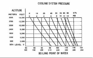
34
KENR6912
Testing and Adjusting Section
Personal injury can result from hot coolant, steam
and alkali.
At operating temperature, engine coolant is hot
and under pressure. The radiator and all lines
to heaters or the engine contain hot coolant or
steam. Any contact can cause severe burns.
Remove filler cap slowly to relieve pressure only
when engine is stopped and radiator cap is cool
enough to touch with your bare hand.
g00296067
Illustration 24
The coolant level must be to the correct level in order
to check the coolant system. The engine must be
cold and the engine must not be running.
Typical schematic of filler cap
(1) Sealing surface between the pressure cap and the radiator
After the engine is cool, loosen the pressure cap
in order to relieve the pressure out of the cooling
system. Then remove the pressure cap.
Personal injury can result from hot coolant, steam
and alkali.
The level of the coolant should not be more than
13 mm (0.5 inch) from the bottom of the filler pipe. If
the cooling system is equipped with a sight glass,
the coolant should be to the correct level in the sight
glass.
At operating temperature, engine coolant is hot
and under pressure. The radiator and all lines
to heaters or the engine contain hot coolant or
steam. Any contact can cause severe burns.
Making the Correct Antifreeze
Mixtures
Remove filler cap slowly to relieve pressure only
when engine is stopped and radiator cap is cool
enough to touch with your bare hand.
Do not add pure antifreeze to the cooling system
in order to adjust the concentration of antifreeze.
Refer to Operation and Maintenance Manual, “Refill
Capacities” for the correct procedure. The pure
antifreeze increases the concentration of antifreeze
in the cooling system. The increased concentration
increases the concentration of dissolved solids and
undissolved chemical inhibitors in the cooling system.
To check for the amount of pressure that opens the
filler cap, use the following procedure:
1. After the engine cools, carefully loosen the filler
cap. Slowly release the pressure from the cooling
system. Then, remove the filler cap.
2. Carefully inspect the filler cap. Look for any
damage to the seals and to the sealing surface.
Inspect the following components for any foreign
substances:
The antifreeze mixture must consist of equal
quantities of antifreeze and clean soft water. The
corrosion inhibitor in the antifreeze will be diluted if a
concentration of less than 50% of antifreeze is used.
Concentrations of more than 50% of antifreeze may
have the adverse effect on the performance of the
coolant.
• Filler cap
• Seal
Checking the Filler Cap
• Surface for seal
Remove any deposits that are found on these
items, and remove any material that is found on
these items.
One cause for a pressure loss in the cooling system
can be a faulty seal on the radiator pressure cap.
3. Install the pressure cap onto a suitable
pressurizing pump.
4. Observe the exact pressure that opens the filler
cap.
This document has been printed from SPI². Not for Resale
![]()
![]()
![]()
![]()
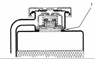
![]()
![]()
KENR6912
35
Testing and Adjusting Section
5. Compare the pressure to the pressure rating that
is found on the top of the filler cap.
i02480718
Engine Oil Cooler - Inspect
6. If the filler cap is damaged, replace the filler cap.
Testing The Radiator And Cooling
System For Leaks
Hot oil and hot components can cause personal
injury. Do not allow hot oil or hot components to
contact the skin.
Use the following procedure to test the radiator and
the cooling system for leaks.
Personal injury can result from hot coolant, steam
and alkali.
At operating temperature, engine coolant is hot
and under pressure. The radiator and all lines
to heaters or the engine contain hot coolant or
steam. Any contact can cause severe burns.
Remove filler cap slowly to relieve pressure only
when engine is stopped and radiator cap is cool
enough to touch with your bare hand.
1. When the engine has cooled, loosen the filler cap
to the first stop. Allow the pressure to release from
the cooling system. Then remove the filler cap.
2. Make sure that the coolant covers the top of the
radiator core.
g01238883
Illustration 25
3. Put a suitable pressurizing pump onto the radiator.
Typical example of an engine oil cooler
(1) Oil cooler base
(2) Oil cooler body
4. Use the pressurizing pump to increase the
pressure to an amount of 20 kPa (3 psi) more than
the operating pressure of the filler cap.
Perform the following procedure in order to inspect
the engine oil cooler:
5. Check the radiator for leakage on the outside.
1. Place a container under the oil cooler in order to
collect any engine oil or coolant that drains from
the oil cooler.
6. Check all connections and hoses of the cooling
system for leaks.
The radiator and the cooling system do not have
leakage if all of the following conditions exist:
2. Refer to Disassembly and Assembly, “Engine Oil
Cooler - Remove” for removal of the engine oil
cooler.
• You do NOT observe any leakage after five
minutes.
3. Thoroughly clean the flange face of the oil cooler
base (1), oil cooler body (2) and the cylinder block.
• The dial indicator remains constant beyond five
minutes.
The inside of the cooling system has leakage only
if the following conditions exist:
Personal injury can result from air pressure.
Personal injury can result without following prop-
er procedure. When using pressure air, wear a pro-
tective face shield and protective clothing.
• The reading on the gauge goes down.
• No external leakage is observed.
Make any repairs, as required.
Maximum air pressure at the nozzle must be less
than 205 kPa (30 psi) for cleaning purposes.
This document has been printed from SPI². Not for Resale
![]()
![]()
![]()
![]()
![]()
![]()
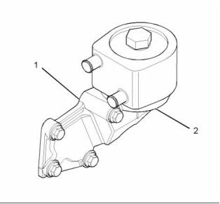
![]()
![]()
36
KENR6912
Testing and Adjusting Section
4. Inspect the oil cooler body (2) for cracks and
dents. Replace the oil cooler body if cracks or
dents exist.
5. After ten minutes, remove the water temperature
regulator housing. Immediately measure the
opening of the water temperature regulator.
Refer to Specifications, “Water Temperature
Regulator” for the minimum opening distance of
the water temperature regulator at the fully open
temperature.
5. If necessary, clean the outside and clean the
inside of the oil cooler base and the oil cooler
body. Use a solvent that is not corrosive on
copper. Ensure that no restrictions for the flow of
lubricating oil exist in the oil cooler base (1) and
oil cooler body (2).
If the distance is less than the amount listed in the
manual, replace the water temperature regulator.
Refer to Disassembly and Assembly, “Water
Temperature Regulator - Remove and Install”.
6. Refer to Disassembly and Assembly, “Engine Oil
Cooler - Install” for installation of the engine oil
cooler.
Install the water temperature regulator. Refer to
Disassembly and Assembly, “Water Temperature
Regulator - Remove and Install”.
7. Ensure that the cooling system of the engine is
filled to the correct level. Refer to Operation and
Maintenance Manual, “Refill Capacities”.
8. Operate the engine. Check for oil or coolant
leakage.
i01889428
Water Temperature Regulator
- Test
Note: Do not remove the water temperature regulator
from the water temperature regulator housing in
order to perform the test.
1. Remove the water temperature regulator housing
which contains the water temperature regulator
from the engine. Refer to Disassembly and
Assembly, “Water Temperature Regulator -
Remove and Install”.
2. Heat water in a pan until the temperature of
the water is equal to the fully open temperature
of the water temperature regulator. Refer to
Specifications, “Water Temperature Regulator”
for the fully open temperature of the water
temperature regulator. Stir the water in the pan.
This will distribute the temperature throughout the
pan.
3. Hang the water temperature regulator housing in
the pan of water. The water temperature regulator
housing must be below the surface of the water.
The water temperature regulator housing must be
away from the sides and the bottom of the pan.
4. Keep the water at the correct temperature for ten
minutes.
This document has been printed from SPI². Not for Resale
![]()
KENR6912
37
Testing and Adjusting Section
Basic Engine
2. Fit new piston rings (2) in the piston grooves (1).
Refer to Disassembly and Assembly, “Pistons
and Connecting Rods - Assemble” for the correct
procedure.
i02875271
Piston Ring Groove - Inspect
3. Check the clearance for the piston ring by placing
Tooling (A) between piston groove (1) and the top
of piston ring (2). Refer to Specifications, “Piston
and Rings” for the dimensions.
Table 9
Required Tools
Inspect the Piston Ring End Gap
Tool
A
Part
Number
Part Description
Qty
1
CVT0014
Feeler Gauge
Inspect the Piston and the Piston
Rings
1. Check the piston for wear and other damage.
2. Check that the piston rings are free to move in the
grooves and that the rings are not broken.
Inspect the Clearance of the Piston
Ring
g01236633
Illustration 27
(A) Feeler Gauge
(1) Piston ring
(2) Cylinder ring ridge
1. Clean all carbon from the top of the cylinder bores.
2. Place each piston ring (1) in the cylinder bore just
below the cylinder ring ridge (2).
g01200845
3. Use Tooling (A) to measure piston ring end gap.
Refer to Specifications, “Piston and Rings” for the
dimensions.
Illustration 26
(A) Feeler gauge
(1) Piston grooves
(2) Piston ring
Note: The coil spring must be removed from the oil
control ring before the gap of the oil control ring is
measured.
1. Remove the piston rings (2). Refer to Disassembly
and Assembly, “Pistons and Connecting Rods -
Disassemble” for the correct procedure. Clean the
grooves (1) and the piston rings (2).
This document has been printed from SPI². Not for Resale
![]()
![]()
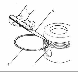
![]()
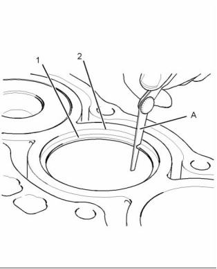
38
KENR6912
Testing and Adjusting Section
i02801084
If the piston pin bearing is not removed, the limits
are reduced to ± 0.06 mm (± 0.0025 inch).
Connecting Rod - Inspect
3. Inspect the piston pin bearing and the piston pin
for wear and other damage.
This procedure determines the following
characteristics of the connecting rod:
4. Measure the clearance of the piston pin in
the piston pin bearing. Refer to Specifications,
“Connecting Rod” for clearance dimensions.
• The distortion of the connecting rod
• The parallel alignment of the bores of the
connecting rod
i01748770
Connecting Rod Bearings -
Inspect
Check the connecting rod bearings and the
connecting rod bearing journal for wear or other
damage.
Connecting rod bearings are available with a smaller
inside diameter than the original size bearings. These
bearings are for crankshafts that have been ground.
i01748792
g01240528
Illustration 28
Main Bearings - Inspect
Inspection of the connecting rod parallel alignment.
(1) Measuring pins
(2) Connecting rod
(L) Measure the distance between the center of the bore for the
piston pin bearing and the center of the connecting rod bearing
bore.
(K) Measure the distance 127 mm (5.0 inch) from the connecting
rod.
Check the main bearings for wear or other damage.
Replace both halves of the bearings and check the
condition of the other bearings if a main bearing is
worn or damaged.
1. Use the appropriate tools in order to measure the
distances for the connecting rod (2).
Main bearings are available with a smaller inside
diameter than the original size bearings. These
bearings are for main bearing journals that have
been ground.
• Appropriate gauges for measuring distance
• Measuring pins (1)
i01946424
Note: The connecting rod bearings should be
removed before taking the measurements.
Cylinder Block - Inspect
2. Measure the connecting rod for distortion and
parallel alignment between the bores.
1. Clean all of the coolant passages and the oil
passages.
The measurements must be taken at distance (K).
Distance (K) has a value of 127 mm (5.0 inch)
from both sides of the connecting rod.
2. Check the cylinder block for cracks and damage.
3. The top deck of the cylinder block must not be
machined. This will affect the piston height above
the cylinder block.
Measure length (L).
The total difference in measurements of length
(L) from each side should not vary more than
± 0.25 mm (± 0.010 inch).
This document has been printed from SPI². Not for Resale
![]()
![]()
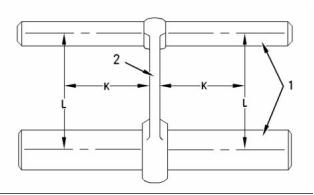
KENR6912
39
Testing and Adjusting Section
4. Check the camshaft bearing for wear. If a new
bearing is needed, use a suitable adapter to press
the bearing out of the bore. Ensure that the oil hole
in the new bearing faces the front of the block.
The oil hole in the bearing must be aligned with
the oil hole in the cylinder block. The bearing must
be aligned with the face of the recess. Refer to
Disassembly and Assembly, “Camshaft Bearings
- Remove and Install”.
i02875284
Cylinder Head - Inspect
g01431057
Illustration 29
Flatness of the cylinder head (typical example)
Table 10
(C) Side to side
(D) End to end
(E) Diagonal
Required Tools
Part
Tool
Part Description
Qty
Number
27610298
-
8. Measure the cylinder head for flatness. Measure
the flatness of the cylinder head with Tooling (A)
and Tooling (B).
A
B
Angled Feeler Gauge
Straight Edge
1
1
• Measure the cylinder head from one side to the
opposite side (C).
1. Remove the cylinder head from the engine.
2. Remove the water temperature regulator housing.
• Measure the cylinder head from one end to the
opposite end (D).
3. Inspect the cylinder head for signs of gas or
coolant leakage.
• Measure the cylinder head from one corner to
the opposite corner (E).
4. Remove the valve springs and valves.
Refer to Specifications, “Cylinder Head” for the
requirements of flatness.
5. Clean the bottom face of the cylinder head
thoroughly. Clean the coolant passages and
the lubricating oil passages. Make sure that the
contact surfaces of the cylinder head and the
cylinder block are clean, smooth and flat.
Remachining the Cylinder Head
The bottom face of cylinder head can be machined if
any of the following conditions exist:
6. Inspect the bottom face of the cylinder head for
pitting, corrosion, and cracks. Inspect the area
around the valve seat inserts and the holes for the
fuel injectors carefully.
• The bottom face of the cylinder head is not flat
within the specifications.
• The bottom face of the cylinder head is damaged
by pitting, corrosion, or wear.
7. Test the cylinder head for leaks at a pressure of
200 kPa (29 psi).
Note: The thickness of the cylinder head must not be
less than 117.20 mm (4.614 inch) after the cylinder
head has been machined.
If the bottom face of the cylinder head has been
remachined, the recesses in the cylinder head for
the valve seat inserts must be machined. The valve
seat inserts must be ground on the side which is
inserted into the cylinder head. Grinding this surface
will ensure that no protrusion exists above the bottom
face of the cylinder head. Refer to Specifications,
“Cylinder Head Valves” for the correct dimensions.
This document has been printed from SPI². Not for Resale
![]()
![]()
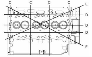
40
KENR6912
Testing and Adjusting Section
i02406197
Piston Height - Inspect
Table 11
Required Tools
Part
Tool
A
Number
21825617
21825496
Part Description
Dial Gauge
Dial gauge holder
Qty
1
B
1
If the height of the piston above the cylinder block
is not within the tolerance that is given in the
Specifications Module, “Piston and Rings”, the
bearing for the piston pin must be checked. Refer to
Testing and Adjusting, “Connecting Rod - Inspect”.
If any of the following components are replaced or
remachined, the piston height above the cylinder
block must be measured:
g01201898
Illustration 30
Typical example
• Crankshaft
1. Use Tooling (A) and Tooling (B) in order to
measure the piston height above the cylinder
block. Use the cylinder block face to zero Tooling
(A).
• Cylinder head
• Connecting rod
• Bearing for the piston pin
2. Rotate the crankshaft until the piston is at the
approximate top center.
The correct piston height must be maintained in order
to ensure that the engine conforms to the standards
for emissions.
3. Position Tooling (B) and Tooling (A) in order to
measure the piston height above the cylinder
block. Slowly rotate the crankshaft in order to
determine when the piston is at the highest
position. Record this dimension. Compare this
dimension with the dimensions that are given in
Specifications, “Piston and Rings”.
Note: The top of the piston should not be machined.
If the original piston is installed, be sure that the
original piston is assembled to the correct connecting
rod and installed in the original cylinder.
Three grades of length of connecting rods determine
the piston height above the cylinder block. The grade
of length of a connecting rod is identified by a letter or
a color. The letter or the color is marked on the side
of the connecting rod. Refer to Testing and Adjusting,
“Connecting Rod - Inspect” and Specifications,
“Connecting Rod” for additional information.
i02875324
Flywheel - Inspect
Table 12
Required Tools
Part
Tool
Part Description
Qty
Number
A
21825617
Dial Gauge
1
This document has been printed from SPI². Not for Resale
![]()
![]()
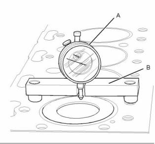
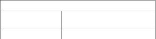
KENR6912
41
Testing and Adjusting Section
Alignment of the Flywheel Face
Flywheel Runout
g01240628
g01240629
Illustration 31
Illustration 32
Typical example
Typical example
1. Install Tooling (A). Refer to Illustration 31.
1. Install Tooling (A). Refer to Illustration 32.
2. Set the pointer of the dial on Tooling (A) to 0 mm
2. Set the pointer of the dial on Tooling (A) to 0 mm
(0 inch).
(0 inch).
3. Turn the flywheel. Read the dial indicator on
3. Turn the flywheel. Read the dial indicator on
Tooling (A) for every 90 degrees.
Tooling (A) for every 90 degrees.
Note: During the check, keep the crankshaft pressed
toward the front of the engine in order to remove any
end clearance.
4. Calculate the difference between the lowest
measurement and the highest measurement of
the four locations. This difference must not be
greater than 0.30 mm (0.012 inch).
4. Calculate the difference between the lowest
measurement and the highest measurement of the
four locations. This difference must not be greater
than 0.03 mm (0.001 inch) for every 25 mm
(1.0 inch) of the radius of the flywheel. The radius
of the flywheel is measured from the axis of the
crankshaft to the contact point of the dial indicator.
i02875327
Flywheel Housing - Inspect
Table 13
Required Tools
Part
Tool
Part Description
Qty
Number
A
21825617
Dial Gauge
1
Concentricity of the Flywheel
Housing
Note: This check must be made with the flywheel
and the starting motor removed and the bolts for the
flywheel housing tightened lightly.
This document has been printed from SPI². Not for Resale
![]()
![]()
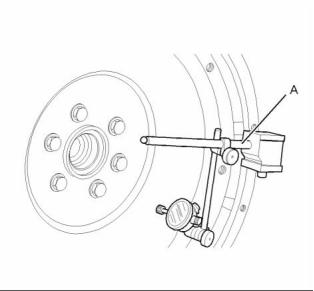
![]()
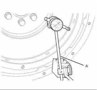
42
KENR6912
Testing and Adjusting Section
g01226662
g01226662
Illustration 33
Illustration 34
Typical example
Typical example
1. Install Tooling (A). Tooling (A) is shown in
Illustration 33.
1. Install Tooling (A). Tooling (A) is shown in
Illustration 34.
2. Set the pointer of Tooling (A) to 0 mm (0 inch).
2. Set the pointer of the dial indicator on Tooling (A)
to 0 mm (0 inch).
3. Check the concentricity at intervals of 90 degrees
around the flywheel housing.
3. Check the alignment at intervals of 90 degrees
around the flywheel housing.
4. Calculate the difference between the lowest
measurement and the highest measurement. This
difference must not be greater than the limit that is
given in Table 14.
4. Calculate the difference between the lowest
measurement and the highest measurement. This
difference must not be greater than the limit that is
given in Table 14.
Note: Any necessary adjustment must be made on
the flywheel housing. Then, recheck the concentricity.
Note: Any necessary adjustment must be made on
the flywheel housing.
Alignment of the Flywheel Housing
Table 14
Limits for Flywheel Housing Runout and Alignment
(Total Indicator Reading)
Note: This check must be made with the flywheel
and the starting motor removed and the bolts for the
flywheel housing tightened to the correct torque.
Refer to Specifications, “Flywheel Housing” for
correct torque.
Bore of the Housing
Flange
Maximum Limit (Total
Indicator Reading)
410 mm (16.14 inch)
0.25 mm (0.010 inch)
This document has been printed from SPI². Not for Resale
![]()
![]()
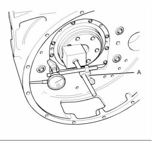
![]()


KENR6912
43
Testing and Adjusting Section
i02484861
4. Measure the backlash between the fuel injection
pump gear (3) and the idler gear (2). Refer to
Specifications, “Gear Group (Front)” for the
backlash measurement.
Gear Group - Inspect
5. Measure the end play on idler gear (2). Refer
to Disassembly and Assembly, “Idler Gear -
Install” for the correct procedure. Refer to the
Specifications, “Gear Group (Front)” for the end
play measurement.
g01194949
Illustration 35
(1) Camshaft gear
(2) Idler gear
(3) Fuel injection pump gear
(4) Crankshaft gear
Note: If one or more of the gears need to be removed
for repair, refer to Disassembly and Assembly, “Gear
Group (Front) - Remove”. Refer to Disassembly and
Assembly, “Gear Group (Front) - Install” in order to
install the gears.
1. Inspect the gears for wear or for damage. If the
gears are worn or damaged, use new parts for
replacement.
g00944084
Illustration 36
2. Measure the backlash between the camshaft
gear (1) and the idler gear (2). Refer to
Specifications, “Gear Group (Front)” for the
backlash measurement.
3. Measure the backlash between the idler gear
(2) and the crankshaft gear (4). Refer to
Specifications, “Gear Group (Front)” for the
backlash measurement.
This document has been printed from SPI². Not for Resale
![]()
![]()
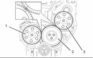
![]()
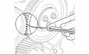
44
KENR6912
Testing and Adjusting Section
Electrical System
4. Turn the ignition switch to the ON position. Check
the voltage between terminal (B) and ground. If
the voltage is more than 2 Volts the alternator
needs to be replaced.
i02875331
Alternator - Test
Warning Light is On When the
Engine is Running
1. Start the engine and run the engine at fast idle.
2. Use a suitable digital multimeter to measure the
battery voltage.
3. Measure the voltage between terminal (A) and
ground.
4. Measure the voltage between terminal (B) and
ground.
5. The measured voltage for terminal (A) and
terminal (B) should be 13 to 15 volts for a 12 volt
system. The measured voltage for terminal (A)
and terminal (B) should be 26 to 30 volts for a 24
volt system.
6. If the voltages do not match replace the alternator.
7. Increase the engine to full throttle. Turn an
g00931045
electrical load ON.
Illustration 37
Typical wiring schematic for an alternator
8. Measure the voltage between terminal (A) and
ground.
(A) Terminal “B+”
(B) Terminal “D+”
(C) Terminal “W”
(D) Ground
9. Measure the voltage between terminal (B) and
(1) Electrical switch
(2) Dash light
ground.
(3) Ignition switch
(4) Battery
10. The measured voltage for terminal (A) and
terminal (B) should be 13 to 15 volts for a 12 volt
system. The measured voltage for terminal (A)
and terminal (B) should be 26 to 30 volts for a 24
volt system.
Warning Lamp Does Not Illuminate
The warning lamp for the charging system should
illuminate when the ignition switch is in the ON
position. Follow the steps below in order to test your
system.
11. Replace the alternator if the voltage does not
match.
1. Check the light bulb. Replace the light bulb if the
i01899136
element is broken.
Battery - Test
2. Use a suitable digital multimeter to check the
battery voltage. Check the battery voltage with the
ignition switch OFF.
Most of the tests of the electrical system can be done
on the engine. The wiring insulation must be in good
condition. The wire and cable connections must be
clean, and both components must be tight.
3. Check the voltage between the terminal (A) and
ground. The measured voltage should equal the
battery voltage.
This document has been printed from SPI². Not for Resale
![]()
![]()
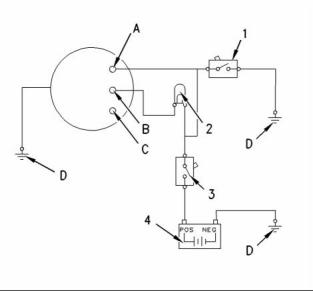
KENR6912
45
Testing and Adjusting Section
When the magnetic force increases in both coils,
the pinion gear moves toward the ring gear of the
flywheel. Then, the solenoid contacts close in order
to provide power to the starting motor. When the
solenoid contacts close, the ground is temporarily
removed from the pull-in coil. Battery voltage is
supplied on both ends of the pull-in coil while the
starting motor cranks. During this period, the pull-in
coil is out of the circuit.
Never disconnect any charging unit circuit or bat-
tery circuit cable from the battery when the charg-
ing unit is operated. A spark can cause an explo-
sion from the flammable vapor mixture of hydro-
gen and oxygen that is released from the elec-
trolyte through the battery outlets. Injury to per-
sonnel can be the result.
Cranking of the engine continues until current to the
solenoid is stopped by releasing the ignition switch.
The battery circuit is an electrical load on the charging
unit. The load is variable because of the condition of
the charge in the battery.
Power which is available during cranking varies
according to the temperature and condition of the
batteries. The following chart shows the voltages
which are expected from a battery at the various
temperature ranges.
NOTICE
The charging unit will be damaged if the connections
between the battery and the charging unit are broken
while the battery is being charged. Damage occurs
because the load from the battery is lost and because
there is an increase in charging voltage. High voltage
will damage the charging unit, the regulator, and other
electrical components.
Table 15
Typical Voltage Of Electrical System During Cranking
At Various Ambient Temperatures
Temperature
12 Volt System
6 to 8 volts
−23 to −7°C (−10 to 20°F)
−7 to 10°C (20 to 50°F)
10 to 27°C (50 to 80°F)
The correct procedures to test the battery can be
found in the manual that is supplied by the OEM.
7 to 9 volts
8 to 10 volts
i02875343
The following table shows the maximum acceptable
loss of voltage in the battery circuit. The battery
circuit supplies high current to the starting motor.
The values in the table are for engines which have
service of 2000 hours or more.
Electric Starting System - Test
General Information
All electrical starting systems have four elements:
• Ignition switch
Table 16
Maximum Acceptable Voltage Drop In The Starting
Motor Circuit During Cranking
Circuit
12 Volt System
• Start relay
Battery post “-” to the starting
motor terminal “-”
0.7 volts
• Starting motor solenoid
• Starting motor
Drop across the disconnect
switch
0.5 volts
Battery post “+” to the terminal 0.5 volts
of the starting motor solenoid
“+”
Start switches have a capacity of 5 to 20 amperes.
The coil of a start relay draws about 1 ampere
between test points. The switch contacts of the start
relay for the starting motor are rated between 100
and 300 amperes. The start relay can easily switch
the load of 5 to 50 amperes for the starting motor
solenoid.
Solenoid terminal “Bat” to the
solenoid terminal “Mtr”
0.4 volts
Voltage drops that are greater than the amounts
in Table 16 are caused most often by the following
conditions:
The starting motor solenoid is a switch with a capacity
of about 1000 amperes. The starting motor solenoid
supplies power to the starter drive. The starting motor
solenoid also engages the pinion to the flywheel.
• Loose connections
• Corroded connections
• Faulty switch contacts
The starting motor solenoid has two coils. The
pull-in coil draws about 40 amperes. The hold-in coil
requires about 5 amperes.
This document has been printed from SPI². Not for Resale
![]()
![]()
![]()
![]()
![]()


46
KENR6912
Testing and Adjusting Section
Diagnosis Procedure
The voltage at the battery post is within 2 volts
of the lowest value in the applicable temperature
range of Table 15.
•
The procedures for diagnosing the starting motor
are intended to help the technician determine if a
starting motor needs to be replaced or repaired. The
procedures are not intended to cover all possible
faults and conditions. The procedures serve only as
a guide.
• The large starting motor cables get hot.
Place the jaws of the ammeter around the cable
that is connected to the “bat” terminal. Refer to
Specifications, “Starting Motor” for the maximum
current that is allowed for no load conditions.
NOTICE
If equipped with electric start, do not crank the engine
for more than 30 seconds. Allow the starter to cool for
two minutes before cranking again.
The current and the voltages that are specified
in Specifications are measured at a temperature
of 27°C (80°F). When the temperature is below
27°C (80°F), the voltage will be lower through the
starting motor. When the temperature is below
27°C (80°F), the current through the starting motor
will be higher. If the current is too great, a fault
exists in the starting motor. Repair the fault or
replace the starting motor.
Never turn the disconnect switch off while the engine
is running. Serious damage to the electrical system
can result.
If the starting motor does not crank or cranks slow,
perform the following procedure:
If the current is within the specification, proceed
to Step 3.
1. Use a suitable digital multimeter in order to
measure the voltage of the battery.
3. Use a suitable digital multimeter in order to
measure the voltage of the starting motor, when
you are cranking or attempting to start the engine.
Measure the voltage across the battery posts
when you are cranking the engine or attempting
to crank the engine. Do not measure the voltage
across the cable post clamps.
a. If the voltage is equal or greater than the
voltage that is given in Table 15, then the
battery and the starting motor cable that goes
to the starting motor are within specifications.
Go to Step 5.
a. If the voltage is equal or greater than the
voltage in Table 15, then go to Step 2.
b. The battery voltage is less than the voltage in
Table 15.
b. The starting motor voltage is less than the
voltage specified in Table 15. The voltage drop
between the battery and the starting motor is
too great. Go to Step 4.
A low charge in a battery can be caused by
several conditions.
• Deterioration of the battery
• A shorted starting motor
• A faulty alternator
4. Use a suitable digital multimeter in order to
measure the voltage.
a. Measure the voltage drops in the cranking
circuits with the multimeter. Compare the
results with the voltage drops which are allowed
in Table 16.
• Loose drive belts
• Current leakage in another part of the
electrical system
b. Voltage drops are equal to the voltage drops
that are given in Table 16 or the voltage drops
are less than the voltage drops that are given
in Table 16. Go to Step 5 in order to check the
engine.
The correct procedures to test the battery can
be found in the manual that is supplied by the
OEM.
c. The voltage drops are greater than the voltage
drops that are given in Table 16. The faulty
component should be repaired or replaced.
2. Use a suitable ammeter in order to measure the
current that is sent to the starting motor solenoid
from the positive post of the battery.
5. Rotate the crankshaft by hand in order to ensure
that the crankshaft is not stuck. Check the oil
viscosity and any external loads that could affect
the engine rotation.
Note: If the following conditions exist, do not perform
the test in Step 2 because the starting motor has a
fault.
This document has been printed from SPI². Not for Resale
![]()
![]()
![]()
KENR6912
47
Testing and Adjusting Section
a. If the crankshaft is stuck or difficult to turn,
Table 17
repair the engine.
12 Volt System
b. If the engine is not difficult to turn, go to Step 6.
6. Attempt to crank the starting motor.
a. The starting motor cranks slowly.
Amp
30
21
14
10
9
Time (sec)
Initial
4
8
Remove the starting motor for repair or
replacement.
20
60
b. The starting motor does not crank.
5. Repeat the procedure in order to check the
Check for the blocked engagement of the
reading on all of the glow plugs.
pinion gear and flywheel ring gear.
6. If there is no reading on the ammeter, check
the electrical connections. If the reading on the
ammeter is low or if the reading is zero, replace
the faulty glow plug.
Note: Blocked engagement and open sol, enoid
contacts will give the same electrical symptoms.
i02875358
Glow Plugs - Test
i02875445
V-Belt - Test
Continuity Check of the Glow Plugs
Table 18
Required Tools
The following test will check the continuity of the glow
plugs.
Part
Tool
Part Name
Qty
Number
1. Disconnect the power supply from the bus bar and
then remove the bus bar.
Belt Tension
Gauge
A
-
1
2. Set a suitable digital multimeter in order to check
continuity (resistance). Turn the audible signal on
the multimeter to the ON position.
3. Place one probe on the connection for the glow
plug and the other probe to a suitable ground.
Tooling (A) should make an audible sound.
Replace the glow plug if there is no continuity.
4. Check the continuity on all the glow plugs.
Checking The Operation of The
Glow Plug
The following test will check the operation of the glow
plugs.
1. Disconnect the power supply from the bus bar and
then remove the bus bar.
2. Connect the power supply to only one glow plug.
3. Place a suitable ammeter on the power supply
wire.
4. Turn the switch to the ON position in order to
activate the glow plug.
This document has been printed from SPI². Not for Resale
![]()

48
KENR6912
Testing and Adjusting Section
Table 19
Belt Tension Chart
Gauge Reading
Size of Belt
Width of Belt
Initial Belt Tension
535 N (120 lb)
Measure the tension of the belt that is farthest from the engine.
(1)
Used Belt Tension
(2)
1/2
13.89 mm (0.547 Inch)
355 N (80 lb)
(1) Initial Belt Tension refers to a new belt.
(2) Used Belt Tension refers to a belt that has been in operation for 30 minutes or more at the rated speed.
1. Check the belts for wear and check the belts for
damage.
g01241384
Illustration 38
Typical example
(A) 144-0235 Belt Tension Gauge
2. Fit Tooling (A) at the center of the longest free
length of the belt and check the tension on
both belts. Check and adjust the tension on the
tightest belt. To adjust the belt tension, refer to
Disassembly and Assembly, “Alternator - Install”.
This document has been printed from SPI². Not for Resale
![]()

![]()
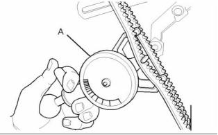
KENR6912
49
Index Section
Index
A
Engine Valve Lash - Inspect/Adjust....................... 25
Valve Lash Adjustment ...................................... 26
Valve Lash Setting ............................................. 25
Excessive Bearing Wear - Inspect......................... 30
Excessive Engine Oil Consumption - Inspect........ 30
Engine Oil Leaks into the Combustion Area of the
Cylinders .......................................................... 30
Engine Oil Leaks on the Outside of the Engine.. 30
Exhaust Temperature - Test................................... 24
Measure the Exhaust Temperature.................... 24
Air in Fuel - Test..................................................... 18
Air Inlet and Exhaust System ............................ 9, 23
Cylinder Head And Valves ................................. 12
Naturally Aspirated Engines............................... 10
Turbocharged Engines......................................... 9
Turbocharger ...................................................... 11
Air Inlet and Exhaust System - Inspect.................. 23
Alternator - Test..................................................... 44
Warning Lamp Does Not Illuminate ................... 44
Warning Light is On When the Engine is
Running............................................................ 44
F
Finding Top Center Position for No. 1 Piston......... 19
Flywheel - Inspect.................................................. 40
Alignment of the Flywheel Face......................... 41
Flywheel Runout................................................ 41
Flywheel Housing - Inspect ................................... 41
Alignment of the Flywheel Housing.................... 42
Concentricity of the Flywheel Housing............... 41
Fuel Injection Pump Timing - Adjust...................... 20
Delphi DP210 and DP310 Fuel Injection Pumps
......................................................................... 20
Fuel Injection Pump Timing - Check...................... 20
Delphi DP210 and DP310 Fuel Injection
B
Basic Engine.................................................... 15, 37
Camshaft............................................................ 16
Crankshaft.......................................................... 16
Cylinder Block and Cylinder Head ..................... 15
Pistons, Rings, and Connecting Rods ............... 16
Battery - Test ......................................................... 44
C
Pumps.............................................................. 20
Fuel Quality - Test.................................................. 20
Fuel System....................................................... 7, 18
Fuel System Components.................................... 8
Fuel System - Inspect............................................ 18
Fuel System - Prime.............................................. 21
Delphi DP210 and DP310.................................. 21
Fuel System Pressure - Test ................................. 21
Check the Function of the Fuel Transfer Pump.. 21
Check the Function of the Pressure Regulator.. 22
Compression - Test................................................ 24
Connecting Rod - Inspect...................................... 38
Connecting Rod Bearings - Inspect....................... 38
Cooling System ............................................... 15, 32
Cooling System - Check (Overheating)................. 32
Cooling System - Inspect....................................... 33
Visual Inspection Of The Cooling System.......... 33
Cooling System - Test............................................ 33
Checking the Filler Cap...................................... 34
Making the Correct Antifreeze Mixtures............. 34
Testing The Radiator And Cooling System For
Leaks................................................................ 35
Cylinder Block - Inspect......................................... 38
Cylinder Head - Inspect......................................... 39
Remachining the Cylinder Head ........................ 39
G
Gear Group - Inspect............................................. 43
General Information................................................. 4
1103D Engine Model Views................................. 6
Engine Description............................................... 4
Lifting the Engine................................................. 5
Glow Plugs - Test................................................... 47
Checking The Operation of The Glow Plug ....... 47
Continuity Check of the Glow Plugs................... 47
E
Electric Starting System - Test............................... 45
Diagnosis Procedure.......................................... 46
General Information........................................... 45
Electrical System............................................. 16, 44
Alternator ........................................................... 17
Starting Motor .................................................... 17
Engine Crankcase Pressure (Blowby) - Test......... 24
Engine Design......................................................... 4
Engine Oil Cooler - Inspect.................................... 35
Engine Oil Pressure - Test..................................... 29
High Oil Pressure............................................... 29
Low Oil Pressure................................................ 29
Engine Oil Pump - Inspect..................................... 29
I
Important Safety Information................................... 2
Increased Engine Oil Temperature - Inspect......... 31
L
Lubrication System.......................................... 13, 29
This document has been printed from SPI². Not for Resale
![]()
50
KENR6912
Index Section
M
Main Bearings - Inspect......................................... 38
P
Piston Height - Inspect .......................................... 40
Piston Ring Groove - Inspect................................. 37
Inspect the Clearance of the Piston Ring........... 37
Inspect the Piston and the Piston Rings ............ 37
Inspect the Piston Ring End Gap....................... 37
S
Systems Operation Section..................................... 4
T
Table of Contents..................................................... 3
Testing and Adjusting Section ............................... 18
V
V-Belt - Test........................................................... 47
Valve Depth - Inspect ............................................ 27
Valve Guide - Inspect ............................................ 27
W
Wastegate - Test.................................................... 23
Water Temperature Regulator - Test ..................... 36
This document has been printed from SPI². Not for Resale