 English
 Espaol
 Franais
 阿拉伯
阿拉伯 中文
中文 Deutsch
 Italiano
 Português
 日本
日本 韩国
韩国 български
 hrvatski
 esky
esky Dansk
Dansk Nederlands
 suomi
suomi Ελληνικ
 印度
印度 norsk
norsk Polski
 Roman
Roman русский
 Svenska
珀金斯403F-15T、404F-22、404F-22T维修保养测试调整供应商,珀金斯403F-15T、404F-22、404F-22T维修保养测试调整技术价格规格咨询服务,珀金斯403F-15T、404F-22、404F-22T维修保养测试调整零配件供应,珀金斯403F-15T、404F-22、404F-22T维修保养测试调整售后服务中心,珀金斯403F-15T、404F-22、404F-22T维修保养测试调整,珀金斯403F-15T、404F-22、404F-22T维修保养测试调整详细的技术参数,

产品中心
珀金斯403F-15T、404F-22、404F-22T维修保养测试调整二(英文)
详细描述
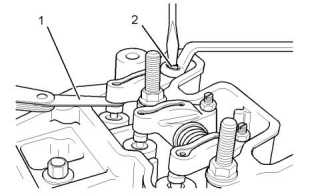
3. Look for any leakage in the connection from the
adapter to the fuel injector (2). If leakage is visible,
make sure that the components are tightened to
the correct torque.
If leakage continues to occur, unscrew the body of
the fuel injector (2) from the nozzle nut. Inspect the
threaded surfaces for foreign particles and
damage.
If the faces are damaged, replace the fuel injector
(2).
If the faces are undamaged, clean the faces.
Repeat Steps 1 and 2. If leakage continues to
occur, replace the fuel injector.
4. Pump the pressure of the injector tester to
approximately 2030 kPa (294 psi) below the
opening pressure of fuel injector (2). Fuel should
not collect on the tip of the fuel injector (2) in a
sufficient quantity in order to drip from the tip for at
least ten seconds. A light dampness is acceptable.
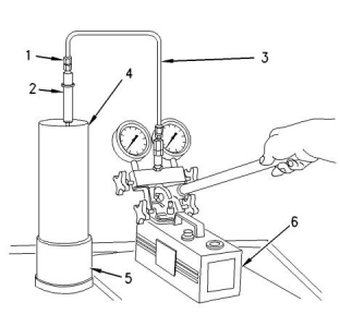
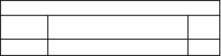
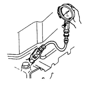
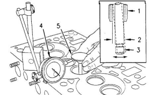
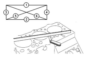
Illustration 46
g00470020
(1) Adapter
If the results of the tests are not acceptable,
replace the fuel injector (2).
(2) Fuel injector
(3) Tube Assembly
(4) Extension
(5) Fuel Collector
(6) Filter
Pressure Test
NOTICE
Do not use dirty test fluids when you test fuel injec-
tors. Also, do not test fuel injectors unless you have
the correct service tools.The use of dirty test fluids
and the use of incorrect service tools will result in
damage to the fuel injectors.
Ensure that you wear eye protection at all times
during testing. When fuel injectors are tested, test
fluids travel through the orifices of the nozzle tip
with high pressure. Under this amount of pres-
sure, the test fluid can pierce the skin and cause
serious injury to the operator. Always keep the tip
of the fuel injector pointed away from the operator
and into the fuel collector and extension.
Note: This procedure is a test of the opening
pressure of the fuel injector.
1. Connect the fuel injector (2) to suitable tooling that
is similar to the Illustration 46 .
The spray from the fuel injector (2) must be
directed into the extension (4) and the fuel
collector (5).
Use clean calibration fluid when the fuel injectors
are tested. The calibration fluid should be
equivalent to SAE J-967 (ISO 4113) oil.
2. Close the gauge protector valve. Close the shutoff
valve. Open the pump isolator valve. Flush the fuel
injector (2) by operating the nozzle tester. Operate
the nozzle tester for 10 to 15 strokes at a rate of
approximately sixty strokes per minute.
This document is printed from SPI². Not for RESALE
![]()
![]()
![]()
![]()
![]()
![]()
![]()
KENR9144
51
Fuel System
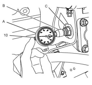
3. Open the gauge protector valve. Slowly increase
the pressure until the valve in the fuel injector (2)
opens. Note the highest pressure indication on the
dial indicator before the pointer moves to 0 kPa
(0 psi). This highest pressure indication is the
opening pressure of fuel injector (2). The opening
pressure occurs when the valve needle is lifted
from the nozzle seat.
1. Connect the fuel injector (2) to suitable tooling that
is similar to the Illustration 47 .
Position the fuel injector (2) so that the direction of
the fuel spray is into the extension (4) and the fuel
collector (5).
2. Close the gauge protector valve and the shutoff
valve. Open the pump isolator valve.
Refer to Specifications, “Fuel Injection Nozzles” for
the correct pressure settings. If the opening
pressure is not within the range of the setting
which is given in the table, the fuel injector (2) must
be replaced.
Test for the Nozzle Spray Pattern
Ensure that you wear eye protection at all times
during testing. When fuel injectors are tested, test
fluids travel through the orifices of the nozzle tip
with high pressure. Under this amount of pres-
sure, the test fluid can pierce the skin and cause
serious injury to the operator. Always keep the tip
of the fuel injector pointed away from the operator
and into the fuel collector and extension.
Illustration 48
g00468241
Phases of operation and spray pattern of the fuel
injector
The spray angle is 4 degrees from the vertical when
the nozzle is fully open.
(A) Closed nozzle
(B) Open nozzle
(C) Fully open nozzle
3. Quickly pump the nozzle tester and look at the
spray pattern when the fluid begins to flow through
the orifices of fuel injector (2) .
The spray flows around the tip of the nozzle. A
difference in the nozzle spray patterns indicates
that the fuel injector (2) is faulty. Refer to the
correct spray pattern in Illustration 48 .
Observe the following characteristics of the spray:
• Drops of fuel should not be in the spray.
• Fuel should be sprayed in the shape of a cone
around the nozzle.
• Fuel should be sprayed evenly in a 360 degree
pattern around the nozzle.
Illustration 47
g00470020
(1) Adapter
(2) Fuel injector
(3) Tube Assembly
(4) Extension
(5) Fuel Collector
(6) Filter
Note: Be sure that the gauge protector valve is
closed before the fuel injector (2) is removed from the
nozzle tester. Closing the valve will prevent damage
to the pressure gauge.
The pressure adjustment must be correct before you
test the spray pattern.
This procedure tests for the correct spray pattern for
the fuel injectors.
This document is printed from SPI². Not for RESALE
![]()
![]()
![]()

![]()
![]()

![]()
![]()
52
KENR9144
Fuel System
i01944302
i02617170
Fuel Quality - Test
Gear Group (Front) - Time
Use the following procedure to test for problems
regarding fuel quality:
1. Determine if water and/or contaminants are
present in the fuel. Check the water separator (if
equipped). If a water separator is not present,
proceed to Step 2. Drain the water separator, if
necessary. A full fuel tank minimizes the potential
for overnight condensation.
Note: A water separator can appear to be full of fuel
when the water separator is actually full of water.
2. Determine if contaminants are present in the fuel.
Remove a sample of fuel from the bottom of the
fuel tank. Visually inspect the fuel sample for
contaminants. The color of the fuel is not
necessarily an indication of fuel quality. However,
fuel that is black, brown, and/or similar to sludge
can be an indication of the growth of bacteria or oil
contamination. In cold temperatures, cloudy fuel
indicates that the fuel may not be suitable for the
operating conditions. Refer to Operation and
Maintenance Manual, “Fuel Recommendations” for
more information.
Illustration 49
g01335186
1. Align timing mark (X) on idler gear (3) with the
timing mark on crankshaft gear (2) and align timing
mark (X) on idler gear (3) with the timing mark on
camshaft gear (1).
3. If fuel quality is still suspected as a possible cause
of problems regarding engine performance,
disconnect the fuel inlet line, and temporarily
operate the engine from a separate source of fuel
that is known to be good. This will determine if the
problem is caused by fuel quality. If fuel quality is
determined to be the problem, drain the fuel
system and replace the fuel filters. Engine
performance can be affected by the following
characteristics:
i05223669
Governor - Adjust
Note: The setting of the front housing is only
necessary if the front housing is damaged or if the
front housing must be renewed.
• Cetane number of the fuel
• Air in the fuel
Table 3
Required Tools
Tool
Part Number
Part Description
Qty
• Other fuel characteristics
A
21825617
Dial Indicator
1
graduated in 0.01 mm
(0.0004 inch)
i04903819
Fuel System - Prime
-
Extension that is 20 mm
(0.787 inch)long
1
B
C
27610331
27610332
Dial holder
1
1
Turn the keyswitch to the ON position for 2 minutes in
order to prime the fuel system. Turn keyswitch to OFF
position, then turn to the ON position again.
Adapter for the cylinder
block
D
E
27610333
-
Calibration spring
1
1
The engine is primed and ready to start.
Allen head screw (M4 x 20
mm x 0.70)
This document is printed from SPI². Not for RESALE

![]()

![]()
![]()
KENR9144
53
Fuel System
Record the Governor Settings
NOTICE
The engine must be in running condition in order to
carry out the governor adjustment procedure. If the
engine cannot be returned to a running condition con-
tact an authorized Perkins distributor
If the front housing has been removed, install the front
housing. Refer to Disassembly and Assembly,
“Housing (Front) - Install”
The setting of the low idle stop screw and the high
idle stop screw must be recorded. The settings are
recorded in order to ensure that the governor
operation is restored.
Note: Engine speed must be recorded from the
crankshaft.
1. Operate the engine until the normal operating
temperature is reached.
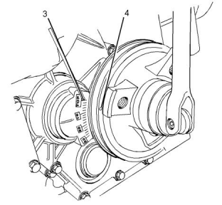
Illustration 51
g03345218
2. Operate the engine at low idle speed. Use the
electronic service tool to record the engine rpm as
“Speed B” .
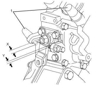
Typical example
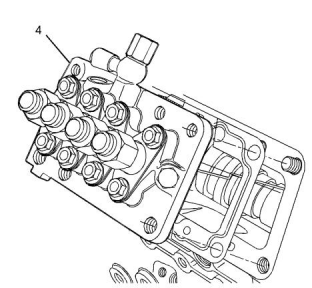
4. Remove tamper proof caps (1).
3. Accelerate the engine to high idle. Use the
electronic service tool to record the engine rpm as
“Speed A” .
5. Record Protrusion (X) of the high idle stop screw
(4).
6. Record Protrusion (Y) of the low idle stop screw
(5).
Note: The recorded “Speed B” will be lower than the
recorded “Speed A” .
Removal of the Old Front Housing
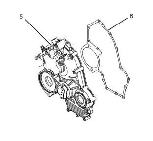
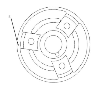
Illustration 50
g01494533
Illustration 52
g03345219
Typical example
Typical example
1. Remove fuel injection pump (4). Refer to
Disassembly and Assembly, “Fuel Injection Pump -
Remove and Install” for the correct procedure.
This document is printed from SPI². Not for RESALE
![]()
![]()
![]()

![]()
![]()

![]()
![]()
![]()
![]()
54
KENR9144
Fuel System
2. Remove the crankshaft pulley. Refer to
Disassembly and Assembly, “Crankshaft Pulley -
Remove”
Illustration 55
g03345224
Typical example
Illustration 53
g03345222
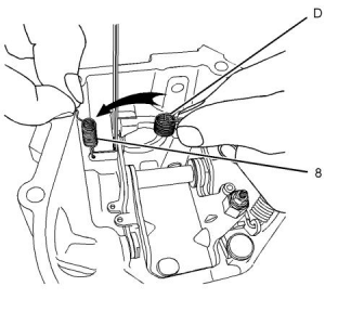
6. Remove start spring (8) and replace the start
spring with Tooling (D).
Typical example
3. Remove front housing (5). Refer to Disassembly
and Assembly, “Housing (Front) - Remove” for the
correct procedure.
7. Install the front housing. Refer to Disassembly and
Assembly, “Housing (Front) - Install” for the correct
procedure.
4. Remove the gasket (6). Ensure that the face of the
Note: Do not install a gasket.
front plate is clean.
8. Install the fuel injection pump to the cylinder block.
Install the original shim. Refer to Disassembly and
Assembly, “Fuel Injection Pump - Remove and
Install” for the correct procedure.
Illustration 54
g03338638
Typical example
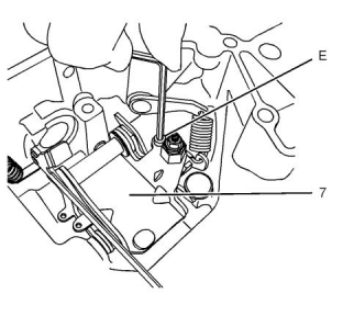
5. Install Tooling (E) to lever assembly (7). Tighten
tooling (E) to a torque of 0.4 N·m (3.540 lb in).
This document is printed from SPI². Not for RESALE
![]()
![]()
![]()
![]()
![]()
![]()
![]()
KENR9144
55
Fuel System
13. Push Tooling (A) into Tooling (B) for a further
2 mm (0.0787 inch). Lock Tooling (B) in order to
retain Tooling (A) in position. Set Tooling (A) to
read 2.00 ± 0.01 mm (0.0787 ± 0.0004 inch).
Illustration 56
g03338639
Typical example
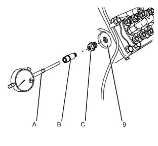
9. Install Tooling (C) into cylinder block (9).
10. Install Tooling (B) into Tooling (C).
11. Assemble Tooling (A).
Illustration 58
g03338641
Typical example
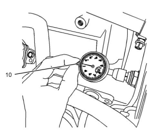
14. Push plunger (10) of Tooling (A) several times in
order to seat the rack of the fuel injection pump.
When the plunger is gently released, check that
Tooling (A) reads 2.00 ± 0.01 mm
12. Install Tooling (A) into Tooling (B) until the
extension on Tooling (A) touches the rack of the
fuel injection pump.
(0.0787 ± 0.0004 inch).
Note: If the rack of the fuel injection pump has heavy
resistance to movement, remove tooling (A). Remove
the fuel injection pump. Wash the fuel injection pump
with a suitable cleaner. Install the fuel injection pump.
Repeat steps 12, 13 and 14.
Setting the New Front Housing
Note: Do not move the position of Tooling (A), Tooling
(B), or Tooling (C) in the cylinder block.
1. Pull plunger (10) of Tooling (A) until the plunger has
reached the fully out position. Use a suitable clip to
retain the plunger in this position.
2. Remove the fuel injection pump. Refer to
Disassembly and Assembly, “Fuel Injection Pump -
Remove and Install” for the correct procedure.
3. Remove the original front housing. Refer to
Disassembly and Assembly, “Housing (Front) -
Remove” for the correct procedure.
Illustration 57
g03338640
Typical example
4. Disassemble the original front housing. Refer to
Disassembly and Assembly, “Housing (Front) -
Disassemble” for the correct procedure.
This document is printed from SPI². Not for RESALE
![]()
![]()
![]()

![]()
![]()
![]()
![]()
56
KENR9144
Fuel System
5. Assemble the replacement front housing with the
parts that were removed from the original front
housing. Install a new fuel screw and a new
locknut. Refer to Disassembly and Assembly,
“Housing (Front) - Assemble” for the correct
procedure.
6. Remove Tooling (E) from the original front housing.
Install Tooling (E) to the lever assembly of the
replacement front housing. Tighten Tooling (E) to a
torque of 0.4 N·m (3.5 lb in).
7. Install the replacement front housing. Refer to
Disassembly and Assembly, “Housing (Front) -
Install” for the correct procedure.
Note: Do not install a gasket.
8. Install the fuel injection pump to the cylinder block.
Install the original shim. Refer to Disassembly and
Assembly, “Fuel Injection Pump - Remove and
Install” for the correct procedure.
Illustration 60
g03338643
Typical example
9. Remove the clip from plunger (10) of Tooling (A).
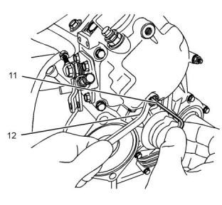
1. Release the plunger on Tooling (A). Do not move
the position of Tooling (A), Tooling (B), or Tooling
(C) in the cylinder block.
Setting the Fuel Screw
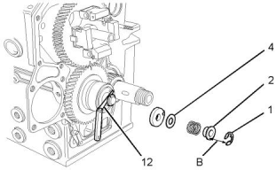
2. Use a ring spanner (Box wrench) (12) to retain the
locknut of the fuel screw in position.
3. Use an allen wrench (11) to rotate the allen head
screw. Observe the reading on the dial indicator.
Adjust the allen head screw until the indicator
reads 2.00 ± 0.01 mm (0.0787 ± 0.0004 inch).
4. Tighten the locknut to a torque of 6 N·m (55 lb in)
in order to retain the allen head screw in position.
The fuel screw is now set.
5. Ensure that the reading of Tooling (A) is
2.00 ± 0.01 mm (0.0787 ± 0.0004 inch).
Final Installationof the New Front
Housing
Illustration 59
g03338642
Typical example
This document is printed from SPI². Not for RESALE
![]()
![]()
![]()
![]()
![]()
KENR9144
57
Fuel System
Illustration 61
g01495413
Typical example
Illustration 63
g03345222
Typical example
1. Remove Tooling (A) and Tooling (B).
2. Remove Tooling (C).
6. Install a new gasket (6). Ensure that the gasket is
clean and free from damage.
3. Remove the fuel injection pump. Refer to
Disassembly and Assembly, “Fuel Injection Pump -
Remove and Install” for the correct procedure.
7. Install the replacement front housing (5) Refer to
Disassembly and Assembly, “Housing (Front) -
Install” for the correct procedure.
4. Remove the front housing. Refer to Disassembly
and Assembly, “Housing (Front) - Remove” for the
correct procedure.
Illustration 64
g01494533
Typical example
Illustration 62
g03338638
Typical example
5. Remove Tooling (E) from lever assembly (7).
This document is printed from SPI². Not for RESALE
![]()

![]()
![]()

![]()
![]()

![]()
![]()
![]()
![]()
58
KENR9144
Fuel System
Illustration 65
g03345218
Illustration 66
g03338646
Typical example
Typical example
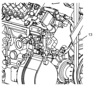
8. Set the Protrusion (X) of the high idle stop screw
(2) to the same dimensions as the stop screws on
the original front housing.
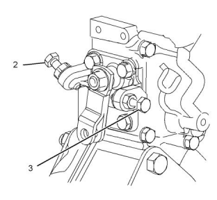
15. Install tamper proof caps (1) to the high idle screw
(2). Install the tamper proof cap (not shown) to fuel
screw (13).
9. Set the Protrusion (Y) of the low idle stop screw (3)
to the same dimensions as the stop screws on the
original front housing.
Note: Care should be taken when the tamper proof
cap is installed to the fuel screw .
10. Install the fuel injection pump to the cylinder
block. Refer to Disassembly and Assembly, “Fuel
Injection Pump - Remove and Install” for the
correct procedure.
11. Start the engine and allow the engine to reach
normal operating temperature.
12. Run the engine at low idle speed. Use the
electronic service tool to check if the engine rpm is
the same as “Speed B” .
13. Run the engine at high idle speed. Use the
electronic service tool to check if the engine rpm is
the same as “Speed A” .
Note: The recorded “Speed A” will be higher than
the recorded “Speed B” .
Note: If “Speed A” does not match the high idle
speed or “Speed B” does not match the low idle
speed, contact Global Technical Support.
14. Ensure correct operation of the engine.
This document is printed from SPI². Not for RESALE
![]()
![]()
![]()
![]()
![]()
KENR9144
59
Air Inlet and Exhaust System
Air Inlet and Exhaust
System
5. If the breather tube is made of plastic, use low
pressure air to check for a blockage in the breather
tube. If a blockage is inside of the connector, the
cover assembly must be replaced. A broken valve
mechanism cover will result if you try to remove the
connection.
i02251899
i05223369
Air Inlet and Exhaust System -
Inspect
Diesel Particulate Filter - Clean
A general visual inspection should be made to the air
inlet and exhaust system. Make sure that there are no
signs of leaks in the system.
Wear goggles, gloves, protective clothing, and a
National Institute for Occupational Safety and
Health (NIOSH) approved P95 or N95 half-face res-
pirator when handling a used Diesel Particulate
Filter or Catalytic Converter Muffler. Failure to do
so could result in personal injury.
There will be a reduction in the performance of the
engine if there is a restriction in the air inlet system or
the exhaust system.
Hot engine components can cause injury from
burns. Before performing maintenance on the en-
gine, allow the engine and the components to
cool.
The muffler, catalytic converter/muffler, and diesel
particulate filter will become extremely hot during
engine operation. A hot muffler, catalytic convert-
er/muffler and diesel particulate filter can cause
serious burns. Allow adequate cooling time be-
fore working on or near the muffler, catalytic con-
verter/muffler and diesel particulate filter.
Making contact with a running engine can cause
burns from hot parts and can cause injury from
rotating parts.
Diesel Particulate Filters (DPF) require periodic
removal of ash that accumulates from engine oil.
When working on an engine that is running, avoid
contact with hot parts and rotating parts.
Cleaning Procedure
Follow this cleaning procedure for removal of the ash
from a DPF. Refer to Operation and Maintenance
Manual for the intervals of service hours for cleaning
of the DPF.
1. Inspect the engine air cleaner inlet and ducting in
order to ensure that the passageway is not blocked
or collapsed.
2. Inspect the engine air cleaner element. Replace a
dirty engine air cleaner element with a clean
engine air cleaner element.
1. Connect the engine to the electronic service tool
before the DPF is removed from the engine. Once
the engine is connected to the electronic service
tool, then perform an ash service test. This test is a
manual regeneration. The test could take an hour.
3. Check for dirt tracks on the clean side of the engine
air cleaner element. If dirt tracks are observed,
contaminants are flowing past the engine air
cleaner element and/or the seal for the engine air
cleaner element.
Note: Allow the DPF to cool until the DPF can be
safely removed.
2. Remove the DPF from the Clean Emissions
Module (CEM). Refer to Disassembly and
Assembly for the correct procedure.
4. For engines with plastic valve mechanism covers, if
you experience excessive crankcase pressure,
remove the valve mechanism cover and check the
end of the shroud for a skin of plastic. If the end of
the shroud has a skin of plastic, remove the skin of
plastic. Ensure that all of the debris is removed.
Note: Identify all engine fault codes if black soot is
discovered on the outlet side of the center section on
the DPF. Refer to Troubleshooting for problem
identification and the disposition of the DPF.
This document is printed from SPI². Not for RESALE
![]()
![]()
![]()
![]()
![]()
![]()
![]()
![]()
![]()
60
KENR9144
Air Inlet and Exhaust System
3. The DPF must be cleaned. Contact your nearest
Perkins distributor for assistance.
When the boost pressure increases against the
diaphragm in the canister, the wastegate will open.
The rpm of the turbocharger becomes limited. The
rpm is limited because a portion of the exhaust gases
bypass the turbine wheel of the turbocharger.
4. Reinstall the DPF onto the Clean Emissions
Module (CEM). Refer to Disassembly and
Assembly for the correct procedure.
The following levels of boost pressure indicate a
problem with the wastegate:
Reset the Engine Ash Model
• Too high in full load conditions
The engine ash model must be reset whenever the
filter is cleaned or replaced. Reseting the ash model
places the DPF volume back to the “Clean State” .
The resetting will allow the regeneration of the DPF to
function properly.
• Too low in all low boost conditions
The boost pressure controls the maximum rpm of the
turbocharger, because the boost pressure controls
the position of the wastegate. The following factors
also affect the maximum rpm of the turbocharger:
1. Use the electronic service tool to access the
configuration parameters. Select “Service” from
the top menu and highlight the “DPF Soot Load
Reset” from the menu in the service tool. The
select the “Reset” option.
• The engine rating
• The horsepower demand on the engine
• The high idle rpm
2. The electronic service tool will display “Reset was
Successful” when the calibration has been
completed.
• Inlet air restriction
• Exhaust system restriction
i03011728
Test the Wastegate for Proper Operation
Wastegate - Test
Table 4
Tools Needed
Part Name
Part
Number
Qty
21825617
Dial Gauge
1
Hot engine components can cause injury from
burns. Before performing maintenance on the en-
gine, allow the engine and the components to
cool.
1. Remove the heat shield from the turbocharger.
Remove the guard for the wastegate.
2. Remove the boost line from the wastegate.
Connect an air supply to the wastegate that can be
adjusted accurately.
Note: The turbocharger is a nonserviceable item. The
pressure for the wastegate can be checked but not
adjusted.
3. Fasten a dial gauge to the turbocharger so that the
end of the actuator rod is in contact with the
plunger of the dial gauge. This will measure axial
movement of the actuator rod.
Before the wastegate is tested, be sure that the inlet
air restriction is within the specifications for your
engine. Be sure that the exhaust system restriction is
within the specifications for your engine. Refer to
Testing and Adjusting, “Air Inlet and Exhaust System -
Inspect”.
4. Slowly apply air pressure to the wastegate so that
the actuator rod moves 1.0 mm (0.039 inch). The
air pressure should be within 52 kPa (7.5 psi).
Ensure that the dial gauge returns to zero when
the air pressure is released. Repeat the test
several times. This will ensure that an accurate
reading is obtained.
Inspection of the Wastegate
The wastegate controls the amount of exhaust gas
that is allowed to bypass the turbine side of the
turbocharger. This valve then controls the rpm of the
turbocharger.
When the engine operates in conditions of low boost,
a spring presses against a diaphragm in the canister.
The actuating rod will move and the wastegate will
close. Then, the turbocharger can operate at
maximum performance.
5. Consult your nearest approved Perkins dealer or
your nearest approved Perkins distributor if the
operation of the wastegate is not correct.
This document is printed from SPI². Not for RESALE
![]()
![]()
![]()
KENR9144
61
Air Inlet and Exhaust System
i05191124
g.
Observe the exhaust gas cooler (NRS) for air
bubbles that indicate a leak. If air bubbles are
seen within 30 seconds, this indicates a leak
with the exhaust gas cooler (NRS). Note the
location or the origin of the leak. Record this
information.
Exhaust Cooler (NRS) - Test
(If Equipped)
Air Under Water Leak Test Procedure.
h.
i.
If no bubbles are detected after 30 seconds,
the exhaust gas cooler (NRS) is reusable.
Remove the exhaust gas cooler (NRS) from
the water. If the exhaust gas cooler (NRS)
does not leak, the problem may be elsewhere
in the cooling system or the engine. Refer the
service manual in order to check for leakage. If
the exhaust gas cooler (NRS) does leak, the
exhaust gas cooler (NRS) should be replaced.
2. Follow steps 2.a. to 2.i. in order to test the gas side
of the exhaust gas cooler (NRS).
a.
b.
c.
Plug the gas inlet (5) of the exhaust gas cooler
(NRS) (2).
Plug the gas outlet port (1) with tube and
pressure regulator assembly.
Make sure that the air pressure regulator is
closed and connect compressed air to the
pressure regulator.
Illustration 67
g03326632
Typical example
1. Follow steps 1.a. to 1.i. in order to test the coolant
side of the exhaust gas cooler (NRS).
d.
e.
Use a suitable pressure gauge in order to
apply an air pressure of 300 kPa (44 psi) to
the exhaust gas cooler (NRS).
a.
b.
c.
Plug the coolant inlet (3) of the exhaust gas
cooler (NRS) (2).
While the exhaust gas cooler (NRS) is still
pressurized, submerge the cooler in water that
is at ambient temperature.
Plug the coolant outlet port (4) with tube and
pressure regulator assembly.
f.
Allow the exhaust gas cooler (NRS) to settle in
order for the air that is trapped to escape.
Make sure that the air pressure regulator is
closed and connect compressed air to the
pressure regulator.
g.
Observe the exhaust gas cooler (NRS) for air
bubbles that indicate a leak. If air bubbles are
seen within 30 seconds, this indicates a leak
with the exhaust gas cooler (NRS). Note the
location or the origin of the leak. Record this
information.
d.
e.
f.
Use a suitable pressure gauge in order to
apply an air pressure of 300 kPa (44 psi) to
the exhaust gas cooler (NRS).
While the exhaust gas cooler (NRS) is still
pressurized, submerge the cooler in water that
is at ambient temperature.
h.
i.
If no bubbles are detected after 30 seconds,
the exhaust gas cooler (NRS) is reusable.
Allow the exhaust gas cooler (NRS) to settle in
order for the air that is trapped to escape.
Remove the exhaust gas cooler (NRS) from
the water. If the exhaust gas cooler (NRS)
does not leak, the problem may be elsewhere
in the cooling system or the engine. Refer the
service manual in order to check for leakage. If
the exhaust gas cooler (NRS) does leak, the
exhaust gas cooler (NRS) should be replaced.
This document is printed from SPI². Not for RESALE
![]()
![]()
![]()
62
KENR9144
Air Inlet and Exhaust System
i02184786
Note: The cylinder compression test should not be
the only test for determining the condition of an
engine.
Compression - Test
Table 5
Standard at
Assembly
Repair Limit
Compression
Compression Pres-
2940 kPa (426 psi) 2450 kPa (355 psi)
The following conditions can affect the results of the
cylinder compression test:
sure(1)
(1)
The compression pressure is taken at 250 rpm.
• The battery is in good condition.
• The battery is fully charged.
6. Repair procedures must be taken if the
compression is lower than the repair limit.
• The starter motor operates correctly.
• The valve lash is set correctly.
• The compression gauge is accurate.
NOTICE
Be sure to measure the compression on all of the cyl-
inders. If all of the cylinders are not checked an im-
proper diagnosis may result. The compression
pressure will vary with the change in engine rpm. It is
necessary to keep the engine rpm constant for all cyl-
inders when you are taking a compression reading.
i04904667
Engine Valve Lash - Inspect/
Adjust
To prevent possible injury, do not use the starter
to turn the flywheel.
Hot engine components can cause burns. Allow
additional time for the engine to cool before meas-
uring valve clearance.
Illustration 68
g00564993
Valve Lash Setting
The valve lash setting is for a cold engine.
Valve lash setting
Checking compression of the engine
1. Remove the fuel injector from the cylinder in order
to measure the compression for that cylinder.
2. Connect a suitable compression gauge to the
cylinder.
Inlet valve.... 0.2 ± 0.05 mm (0.008 ± 0.0020 inch)
Exhaust valve.................................0.2 ± 0.05 mm
(0.008 ± 0.0020 inch)
3. Disconnect the fuel shutoff solenoid.
Valve Lash Adjustment
4. Operate the starter motor and record the pressure
on the compression gauge.
If the valve lash requires adjustment several times in
a short time period, excessive wear exists in a
different part of the engine. Repair the problem in
order to prevent more damage to the engine.
5. Repeat for each cylinder.
Note: Compression tests should only be used to
compare pressures between cylinders of an engine. If
one or more cylinders vary more than 350 kPa
(51 psi) then those cylinders may be damaged.
Not enough valve lash can be the cause of rapid wear
of the camshaft and valve lifters. Not enough valve
lash can indicate that the seats for the valves are
worn.
Valves become worn due to the following causes:
This document is printed from SPI². Not for RESALE
![]()
![]()
![]()
![]()
![]()
![]()
![]()
KENR9144
63
Air Inlet and Exhaust System
• Incorrect operation of fuel injectors
• Excessive dirt and oil are present on the filters for
the inlet air.
Accidental engine starting can cause injury or
death to personnel.
• Incorrect fuel settings on the fuel injection pump.
To prevent accidental engine starting, turn the
ignition switch to the OFF position and place a do
not operate tag at the ignition switch location.
• The load capacity of the engine is frequently
exceeded.
Too much valve lash can cause broken valve stems,
springs, and spring retainers. Too much valve lash
can be an indication of the following problems:
Valve Lash Adjustment for Three Cylinder
Engines
• Worn camshaft and valve lifters
• Worn rocker arms
NOTICE
Ensure that this valve lash adjustment procedure is
followed for the three cylinder engine. Do not use the
traditional opposing cylinders method. Failure to fol-
low the correct procedure may result in serious en-
gine damage.
• Bent pushrods
• Broken socket on the upper end of a pushrod
• Loose adjustment screw for the valve lash
If the camshaft and valve lifters show rapid wear, look
for fuel in the lubrication oil or dirty lubrication oil as a
possible cause.
Firing order for the three cylinder engine ...........1, 2, 3
The valve lash is measured between the top of the
valve stem and the rocker arm lever.
Note: No. 1 cylinder is at the front of the engine.
Remove the valve mechanism cover and perform the
following procedures in order to adjust the valve lash:
Note: When these procedures are performed, the
front housing must be installed.
Illustration 69
g01107989
Setting the valve lash
Illustration 70
g03340757
(1) Feeler gauge
(2) Adjustment screw
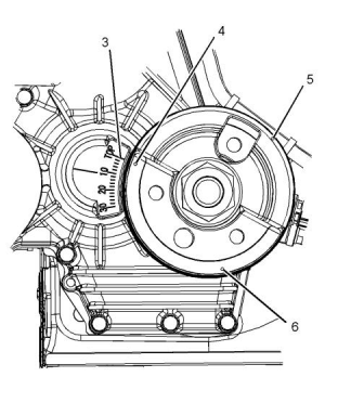
A typical example of the crankshaft pulley and front
housing
This document is printed from SPI². Not for RESALE
![]()
![]()
![]()
![]()
![]()
![]()
![]()
![]()
![]()
64
KENR9144
Air Inlet and Exhaust System
If adjustment is necessary, refer to steps 2.a., 2.b.,
and 2.c..
4. Rotate the crankshaft in a clockwise direction that
is viewed from the front of the engine. Rotate the
crankshaft clockwise until the piston of No. 3
cylinder is at the top center position on the
compression stroke. Ensure that the “Top” mark
(3) on the timing case aligns with “Dot” (6) on the
crankshaft pulley. Check the valve lash of the inlet
valve for No. 3 cylinder and the exhaust valve for
No. 3 cylinder.
If adjustment is necessary, refer to steps 2.a., 2.b.,
and 2.c..
Valve Lash Adjustment for Four Cylinder
Engines
Illustration 71
g03340758
Top center markings for the Crankshaft pulley
1. Rotate the crankshaft clockwise until the piston of
No. 1 cylinder is at the top center position on the
compression stroke. Refer to Systems Operation,
Testing and Adjusting, “Finding Top Center
Position for No. 1 Piston” for the correct procedure.
Ensure that the “Top” mark (3) on the timing case
aligns with “Dot” (4) on the crankshaft pulley.
2. Check the valve lash of the inlet valve of No. 1
cylinder and the exhaust valve of No. 1 cylinder. If
necessary, make adjustment.
a.
Loosen the valve adjustment screw locknut
that is on adjustment screw (2).
b.
Place the appropriate feeler gauge (1)
between the rocker arm and the valve. Turn
adjustment screw (2) while the valve
adjustment screw locknut is being held from
turning. Adjust the valve lash until the correct
specification is achieved.
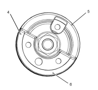
Illustration 72
g03340755
A typical example of the crankshaft pulley and front
housing
c.
After each adjustment, tighten the valve
adjustment screw locknut while adjustment
screw (2) is being held from turning.
3. Rotate the crankshaft in a clockwise direction that
is viewed from the front of the engine. Rotate the
crankshaft clockwise until the piston of No. 2
cylinder is at the top center position on the
compression stroke. Ensure that the “Top” mark
(3) on the timing case aligns with “Dot” (5) on the
crankshaft pulley. Check the valve lash of the inlet
valve for No. 2 cylinder and the exhaust valve for
No. 2 cylinder.
This document is printed from SPI². Not for RESALE
![]()
![]()
![]()
![]()
![]()
KENR9144
65
Air Inlet and Exhaust System
2. Rotate the crankshaft in a clockwise direction 360°.
When the inlet valve of the No. 1 cylinder has
started to open and the exhaust valve of the No. 1
cylinder has not closed, ensure that the “Top”
mark (3) on the timing case aligns with “Single
dot” (4) on the crankshaft pulley. Check the valve
lash of the exhaust valve of the No. 2 cylinder.
Check the valve lash of the inlet valve of the No. 3
cylinder. Check the valve lash of the inlet valve and
the exhaust valve of the No. 4 cylinder. If
necessary, make an adjustment.
If adjustment is necessary, refer to Steps 1.a., 1.b.,
and 1.c. above.
i02193792
Valve Depth - Inspect
Table 6
Illustration 73
g03340756
Top center markings for the Crankshaft pulley
Required Tools
Part Number
21825617
21825496
Part Description
Dial gauge
Qty
1
1. Rotate the crankshaft in a clockwise direction that
is viewed from the front of the engine. When the
inlet valve of the No. 4 cylinder has started to open
and the exhaust valve of the No. 4 cylinder has not
closed, ensure that the “Top” mark (3) on the
timing case aligns with “Single dot” (4) on the
crankshaft pulley. Check the valve lash of the inlet
valve and the exhaust valve of the No. 1 cylinder.
Check the valve lash of the inlet valve of the No. 2
cylinder. Check the valve lash of the exhaust valve
of the No. 3 cylinder. If necessary, make an
adjustment.
Dial gauge holder
1
Note: The “Single dot” (4) on the crankshaft pulley is
the reference point for the top center position of No. 1
cylinder.
a.
Loosen the valve adjustment screw locknut
that is on adjustment screw (2).
b.
Place the appropriate feeler gauge (1)
between the rocker arm and the valve. Turn
adjustment screw (2) while the valve
adjustment screw locknut is being held from
turning. Adjust the valve lash until the correct
specification is achieved.
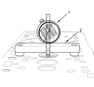
Illustration 74
g00953530
(1) Dial gauge
(2) Dial gauge holder
c.
After each adjustment, tighten the valve
adjustment screw locknut while adjustment
screw (2) is being held from turning.
1. Use the dial gauge (1) with the dial gauge holder
(2) to check the depths of the inlet valves and the
exhaust valves below the face of the cylinder head.
Use the cylinder head face (3) to zero the dial
gauge (1).
This document is printed from SPI². Not for RESALE
![]()
![]()
![]()
![]()
![]()
66
KENR9144
Air Inlet and Exhaust System
2. Position the dial gauge holder (2) and the dial
gauge (1) in order to measure the valve depth.
Measure the depth of the inlet valve and the
exhaust valve before the valve springs are
removed.
4. Move the valve in a radial direction away from the
dial indicator. Make sure that the valve moves
away from the dial indicator as far as possible.
Position the contact point of the dial indicator on
the edge of the valve head. Set the position of the
needle of the dial indicator to zero.
Refer to Specifications, “Cylinder Head Valves” for
the minimum, the maximum, and the service wear
limits for the valve depth below the cylinder head
face.
5. Move the valve in a radial direction toward the dial
indicator as far as possible. Note the distance of
movement which is indicated on the dial indicator.
If the distance is greater than the maximum
clearance of the valve in the valve guide, replace
the valve guide. Refer to Specifications, “Cylinder
Head Valves” for the maximum clearance of the
valve in the valve guide.
If the valve depth below the cylinder head face
exceeds the service limit, use a new valve to check
the valve depth. If the valve depth still exceeds the
service limit, renew the cylinder head or renew the
valve seat inserts (if equipped). If the valve depth
is within the service limit, renew the valves.
3. Inspect the valves for cracks and other damage.
Check the valve stems for wear. Check that the
valve springs are the correct length under the test
force. Refer to Specifications, “Cylinder Head
Valves” for the dimensions and tolerances of the
valves and valve springs.
i01962876
Valve Guide - Inspect
Perform this test in order to determine if a valve guide
should be replaced.
Illustration 75
g00314806
(1) Valve guide
(2) Radial movement of the valve in the valve guide
(3) Valve stem
(4) Dial indicator
(5) Valve head
1. Place a new valve in the valve guide.
2. Place the dial indicator with the magnetic base on
the face of the cylinder head.
3. Lift the edge of the valve head to a distance of
15.0 mm (0.60 inch).
This document is printed from SPI². Not for RESALE
![]()
![]()
![]()
KENR9144
67
Lubrication System
LubricationSystem
Perform the following procedures in order to inspect
the engine oil pump. Refer to Specifications, “Engine
Oil Pump”.
i02193793
Engine Oil Pressure - Test
An oil pressure gauge that has a defect can indicate
low oil pressure.
Use a suitable gauge that measures the oil pressure
in the engine.
1. Ensure that the engine is filled to the correct oil
level.
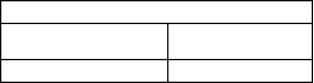
Illustration 76
g00458938
2. Connect the gauge to a pressure tap location for
Idler gear and components of the engine oil pump
engine oil.
(1) C-clip
(2) Collar
(3) Spring
3. Operate the engine. Allow the engine to obtain
(4) Shim
normal operating temperature.
(5) Oil pump cover
(6) Inner rotor
(7) Spring
(8) Outer rotor
(9) Bushing
(10) Idler gear
(11) Thrust washer
4. Keep the oil temperature constant with the engine
at the rated rpm. Read the pressure gauge.
5. Refer to Table 7 in order to determine if the engine
oil pressure is in tolerance.
Table 7
1. Remove the front housing. Remove C-clip (1).
Oil Pressure(1)
Note: If the front housing is removed, do not turn the
crankshaft.
196 to 441 kPa
Oil Pressure at high idle
(28.4 to 64 psi)
2. Disassemble the engine oil pump. Refer to
Disassembly and Assembly, “Engine Oil Pump -
Remove” for additional information. Do not remove
bushing (9) from idler gear (10) unless damage is
observed.
Oil Pressure at low idle
49 kPa (7.1 psi) or more
(1)
The oil temperature must be 80° to 110°C (176° to 230°F).
Troubleshoot the cause of the problem and correct
the problem if the results of the test do not fall within
the pressure range in Table 7 . Engine failure or a
reduction in engine life can be the result if engine
operation is continued with oil pressure outside this
range.
3. Clean all of the parts and inspect the parts for
cracks in the metal or other damage. Look for wear
on the components. Ensure that bushing (9) is not
loose in idler gear (10).
Note: A record of engine oil pressure at regular
intervals can be used as an indication of possible
problems of the engine. A record of engine oil
pressure at regular intervals can also be used as an
indication of possible damage to the engine. The
engine should be inspected and the problem should
be corrected if there is a sudden increase or a sudden
decrease of 70 kPa (10 psi) in oil pressure.
i02617860
Engine Oil Pump - Inspect
If any part of the engine oil pump is worn enough in
order to affect the performance of the engine oil
pump, the engine oil pump must be replaced.
This document is printed from SPI². Not for RESALE
![]()
![]()
![]()
68
KENR9144
Lubrication System
The distance between the faces is adjusted with
shims (4). The thicknesses of the shims are given
in Specifications, “Engine Oil Pump”.
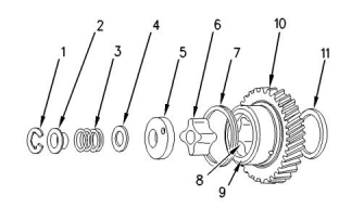
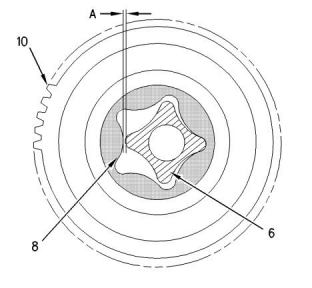
Illustration 79
g00826185
7. Install the components of the engine oil pump and
the front housing on the cylinder block. Make sure
that the two dowels align with the bushing, the
outer rotor, and the holes in the idler gear.
Illustration 77
g00459701
Clearance between the inner rotor and the outer rotor
4. Install the idler gear and the inner rotor on the
shaft. Measure clearance (A) between inner rotor
(6) and outer rotor (8).
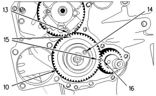
Align the timing mark (15) on idler gear (10) with
the timing mark on crankshaft gear (16) when you
install the idler gear on the oil pump shaft. Also,
align the other timing mark (15) on idler gear (10)
with the timing mark on the camshaft gear (13).
The hole (14) in oil pump cover (5) should align
with the locating pin in the front housing.
Refer to Specifications, “Engine Oil Pump”.
Note: When the front housing is not installed on the
engine, do not rotate the crankshaft.
i01126690
Excessive Bearing Wear -
Inspect
When some components of the engine show bearing
wear in a short time, the cause can be a restriction in
an oil passage.
Illustration 78
g01290817
Face of the cover for the oil pump above the face of
the idler gear
An engine oil pressure indicator may show that there
is enough oil pressure, but a component is worn due
to a lack of lubrication. In such a case, look at the
passage for the oil supply to the component. A
restriction in an oil supply passage will not allow
enough lubrication to reach a component. This will
result in early wear.
(1) C-clip
(2) Collar
(4) Shim
(12) Feeler gauge
5. Use feeler gauge (12) to measure the distance
between C-clip (1) and collar (2).
6. When the components of the engine oil pump are
installed on the front housing, measurement (B)
between C-clip (1) and collar (2) must be between
0.10 to 0.15 mm (0.004 to 0.006 inch)for new
components. Dimension B must be not more than
0.20 mm (0.008 inch) for used parts.
This document is printed from SPI². Not for RESALE
![]()
![]()
![]()
![]()
![]()
![]()
![]()
KENR9144
69
Lubrication System
i03993149
Excessive Engine Oil
Consumption - Inspect
Engine Oil Leaks on the Outside of
the Engine
Check for leakage at the seals at each end of the
crankshaft. Look for leakage at the gasket for the
engine oil pan and all lubrication system connections.
Look for any engine oil that may be leaking from the
crankcase breather. This can be caused by
combustion gas leakage around the pistons. A dirty
crankcase breather will cause high pressure in the
crankcase. A dirty crankcase breather will cause the
gaskets and the seals to leak.
Engine Oil Leaks into the
Combustion Area of the Cylinders
Engine oil that is leaking into the combustion area of
the cylinders can be the cause of blue smoke. There
are several possible ways for engine oil to leak into
the combustion area of the cylinders:
• Leaks between worn valve guides and valve stems
• Worn components or damaged components
(pistons, piston rings, or dirty return holes for the
engine oil)
• Incorrect installation of the compression ring and/
or the intermediate ring
• Leaks past the seal rings in the turbocharger shaft
• Overfilling of the crankcase
• Wrong oil level gauge or guide tube
• Sustained operation at light loads
Excessive consumption of engine oil can also result if
engine oil with the wrong viscosity is used. Engine oil
with a thin viscosity can be caused by increased
engine temperature.
This document is printed from SPI². Not for RESALE
![]()
70
KENR9144
Cooling System
Cooling System
b.
Check for debris or damage between the fins
of the radiator core. Debris between the fins of
the radiator core restricts air flow through the
radiator core. Refer to Testing and Adjusting,
“Cooling System - Inspect”.
i02193795
Cooling System - Check
(Overheating)
6. Check the filler cap. A pressure drop in the cooling
system can cause the boiling point to be lower.
This can cause the cooling system to boil. Refer to
Testing and Adjusting, “Cooling System - Test”.
Above normal coolant temperatures can be caused
by many conditions. Use the following procedure to
determine the cause of above normal coolant
temperatures:
7. Check the fan and/or the fan shroud. The fan
shroud must be the proper size and the fan shroud
must be positioned correctly.
1. Check the coolant level in the cooling system. If the
coolant level is too low, air will get into the cooling
system. Air in the cooling system will cause a
reduction in coolant flow and bubbles in the
coolant. Air bubbles will keep the coolant away
from the engine parts, which will prevent the
transfer of heat to the coolant. Low coolant level is
caused by leaks or incorrectly filling the expansion
tank.
8. Check for loose drive belts.
a.
A loose fan drive belt will cause a reduction in
the air flow across the radiator. Check the fan
drive belt for proper belt tension. Adjust the
tension of the fan drive belt, if necessary. Refer
to the Testing and Adjusting Section, “Belt
Tension Chart”.
b.
A loose water pump drive belt will cause a
reduction in coolant flow through the radiator.
Check the water pump drive belt for proper belt
tension. Adjust the water pump drive belt's
tension, if necessary. Refer to the Testing and
Adjusting Section, “Belt Tension Chart”.
2. If contamination of the coolant is suspected, refer
to Operation and Maintenance, “Maintenance
Section”for the correct specification of coolant.
3. Check for air in the cooling system. Air can enter
the cooling system in different ways. The most
common causes of air in the cooling system are
not filling the cooling system correctly and
combustion gas leakage into the cooling system.
Combustion gas can get into the system through
inside cracks, a damaged cylinder head, or a
damaged cylinder head gasket. Air in the cooling
system causes a reduction in coolant flow and
bubbles in the coolant. Air bubbles keep the
coolant away from the engine parts, which
prevents the transfer of heat to the coolant.
9. Check the cooling system hoses and clamps.
Damaged hoses with leaks can normally be seen.
Hoses that have no visual leaks can soften during
operation. The soft areas of the hose can become
kinked or crushed during operation. These areas of
the hose can cause a restriction in the coolant flow.
Hoses become soft and/or get cracks after a
period of time. The inside of a hose can
deteriorate, and the loose particles of the hose can
cause a restriction of the coolant flow.
10. Check for a restriction in the air inlet system. A
restriction of the air that is coming into the engine
can cause high cylinder temperatures. High
cylinder temperatures require higher than normal
temperatures in the cooling system.
4. Check the sending unit. In some conditions, the
temperature sensor in the engine sends signals to
a sending unit. The sending unit converts these
signals to an electrical impulse which is used by a
mounted gauge. If the sending unit malfunctions,
the gauge can show an incorrect reading. Also if
the electric wire breaks or if the electric wire shorts
out, the gauge can show an incorrect reading.
11. Check for a restriction in the exhaust system. A
restriction of the air that is coming out of the engine
can cause high cylinder temperatures.
5. Check the radiator.
a.
Make a visual inspection of the exhaust
system.
a.
Check the radiator for a restriction to coolant
flow. Check the radiator for debris, dirt, or
deposits on the inside of the core. Debris, dirt,
or deposits will restrict the flow of coolant
through the radiator.
b.
Check for damage to exhaust piping. Check
for damage to the exhaust elbow. If no damage
is found, check the exhaust system for a
restriction.
This document is printed from SPI². Not for RESALE
![]()
KENR9144
71
Cooling System
12. Check the water temperature regulator. A water
temperature regulator that does not open, or a
water temperature regulator that only opens part of
the way can cause overheating. Refer to Testing
and Adjusting, “Water Temperature Regulator -
Test”.
Note: A small amount of coolant leakage across the
surface of the water pump seals is normal. This
leakage is required in order to provide lubrication for
this type of seal. A hole is provided in the water pump
housing in order to allow this coolant/seal lubricant to
drain from the pump housing. Intermittent leakage of
small amounts of coolant from this hole is not an
indication of water pump seal failure.
13. Check the water pump. A water pump with a
damaged impeller does not pump enough coolant
for correct engine cooling. Remove the water
pump and check for damage to the impeller.
3. Make sure that air flow through the radiator does
not have a restriction. Look for bent core fins
between the folded cores of the radiator. Also, look
for debris between the folded cores of the radiator.
14. Consider high outside temperatures. When
outside temperatures are too high for the rating of
the cooling system, there is not enough of a
temperature difference between the outside air and
coolant temperatures. The maximum temperature
of the ambient air that enters the engine should not
exceed 50 °C (120 °F).
4. Inspect the drive belts for the fan.
5. Check for damage to the fan blades.
6. Look for air or combustion gas in the cooling
system.
15. When a load that is applied to the engine is too
large, the engine rpm does not increase with an
increase of fuel. This lower engine rpm causes a
reduction in coolant flow through the system. This
combination of less air and less coolant flow during
high input of fuel will cause above normal heating.
7. Inspect the filler cap, and check the surface that
seals the filler cap. This surface must be clean.
8. Look for large amounts of dirt in the radiator core.
Look for large amounts of dirt on the engine.
Remove the dirt from the radiator core and the
engine.
16. Timing of the engine which is incorrect may also
cause overheating of the engine. Late timing
creates more heat in the engine. Early timing
creates less heat in the engine.
9. Fan shrouds that are loose or missing cause poor
air flow for cooling.
i01964006
Note: If the timing of the engine is incorrect, the
exhaust valves may be burned and damage to the
exhaust manifold may occur.
Cooling System - Test
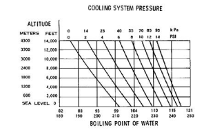
Remember that temperature and pressure work
together. When a diagnosis is made of a cooling
system problem, temperature and pressure must be
checked. The cooling system pressure will have an
effect on the cooling system temperature. For an
example, refer to Illustration 80 . This will show the
effect of pressure on the boiling point (steam) of
water. This will also show the effect of height above
sea level.
i01300404
Cooling System - Inspect
Cooling systems that are not regularly inspected are
the cause for increased engine temperatures. Make a
visual inspection of the cooling system before any
tests are performed.
Personal injury can result from escaping fluid
under pressure.
If a pressure indication is shown on the indicator,
push the release valve in order to relieve pressure
before removing any hose from the radiator.
1. Check the coolant level in the cooling system.
2. Look for leaks in the system.
This document is printed from SPI². Not for RESALE
![]()
![]()
![]()
72
KENR9144
Cooling System
Illustration 80
g00286266
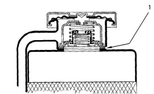
Illustration 81
g00296067
Cooling system pressure at specific altitudes and
boiling points of water
Typical schematic of filler cap
(1) Sealing surface between the pressure cap and the radiator
Personal injury can result from hot coolant, steam
and alkali.
Personal injury can result from hot coolant, steam
and alkali.
At operating temperature, engine coolant is hot
and under pressure. The radiator and all lines to
heaters or the engine contain hot coolant or
steam. Any contact can cause severe burns.
At operating temperature, engine coolant is hot
and under pressure. The radiator and all lines to
heaters or the engine contain hot coolant or
steam. Any contact can cause severe burns.
Remove filler cap slowly to relieve pressure only
when engine is stopped and radiator cap is cool
enough to touch with your bare hand.
Remove filler cap slowly to relieve pressure only
when engine is stopped and radiator cap is cool
enough to touch with your bare hand.
The coolant level must be to the correct level in order
to check the coolant system. The engine must be cold
and the engine must not be running.
To check for the amount of pressure that opens the
filler cap, use the following procedure:
1. After the engine cools, carefully loosen the filler
cap. Slowly release the pressure from the cooling
system. Then, remove the filler cap.
After the engine is cool, loosen the pressure cap in
order to relieve the pressure out of the cooling
system. Then remove the pressure cap.
The level of the coolant should not be more than
13 mm (0.5 inch) from the bottom of the filler pipe. If
the cooling system is equipped with a sight glass, the
coolant should be to the correct level in the sight
glass.
2. Inspect the pressure cap carefully. Look for
damage to the seal. Look for damage to the
surface that seals. Remove any debris on the cap,
the seal, or the sealing surface.
Carefully inspect the filler cap. Look for any
damage to the seals and to the sealing surface.
Inspect the following components for any foreign
substances:
Checking the Filler Cap
One cause for a pressure loss in the cooling system
can be a faulty seal on the radiator pressure cap.
• Filler cap
• Seal
• Surface for seal
Remove any deposits that are found on these
items, and remove any material that is found on
these items.
3. Install the pressure cap onto a suitable
pressurizing Pump.
This document is printed from SPI². Not for RESALE
![]()
![]()
![]()
![]()
![]()
![]()
![]()
![]()
![]()
KENR9144
73
Cooling System
4. Observe the exact pressure that opens the filler
i05183360
cap.
Water Temperature Regulator -
Test
5. Compare the pressure to the pressure rating that is
found on the top of the filler cap.
6. If the filler cap is damaged, replace the filler cap.
Introduction
Testing The Radiator And Cooling
System For Leaks
This procedure is intended to give information on
testing the water temperature regulator.
Use the following procedure to test the radiator and
the cooling system for leaks.
Test Procedure
Personal injury can result from escaping fluid
under pressure.
Personal injury can result from hot coolant, steam
and alkali.
If a pressure indication is shown on the indicator,
push the release valve in order to relieve pressure
before removing any hose from the radiator.
At operating temperature, engine coolant is hot
and under pressure. The radiator and all lines to
heaters or the engine contain hot coolant or
steam. Any contact can cause severe burns.
1. Remove the water temperature regulator from the
engine.
Remove filler cap slowly to relieve pressure only
when engine is stopped and radiator cap is cool
enough to touch with your bare hand.
2. Heat water in a pan until the temperature of the
water is equal to the fully open temperature of the
water temperature regulator. Refer to
Specifications, “Water Temperature Regulator” for
the fully open temperature of the water
temperature regulator. Stir the water in the pan.
This will distribute the temperature throughout the
pan.
1. When the engine has cooled, loosen the filler cap
to the first stop. Allow the pressure to release from
the cooling system. Then remove the filler cap.
2. Make sure that the coolant covers the top of the
radiator core.
3. Put a suitable pressurizing Pump onto the radiator.
3. Hang the water temperature regulator in the pan of
water. The water temperature regulator must be
below the surface of the water. The water
temperature regulator must be away from the sides
and the bottom of the pan.
4. Use the pressurizing pump to increase the
pressure to an amount of 20 kPa (3 psi) more than
the operating pressure of the filler cap.
5. Check the radiator for leakage on the outside.
4. Keep the water at the correct temperature for ten
minutes.
6. Check all connections and hoses of the cooling
system for leaks.
5. After ten minutes, remove the water temperature
regulator. Immediately measure the opening of the
water temperature regulator. Refer to
Specifications, “Water Temperature Regulator” for
the minimum opening distance of the water
temperature regulator at the fully open
temperature.
The radiator and the cooling system do not have
leakage if all of the following conditions exist:
• You do NOTobserve any leakage after five
minutes.
• The dial indicator remains constant beyond five
minutes.
If the distance is less than the amount listed in the
manual, replace the water temperature regulator.
The inside of the cooling system has leakage only
if the following conditions exist:
i02193835
• The reading on the gauge goes down.
Water Pump - Inspect
• You do NOTobserve any outside leakage.
Make any repairs, as required.
This document is printed from SPI². Not for RESALE
![]()
![]()
![]()
![]()
![]()
74
KENR9144
Cooling System
Illustration 82
g01109205
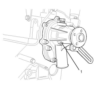
1. Start the engine. Inspect the water pump for
excessive leaks at the vent hole (1).
Note: A small amount of coolant leakage across the
surface of the seal for the jacket water pump is
normal. This leakage is required to provide lubrication
for this type of seal. A hole is provided in the water
pump housing in order to allow this coolant/seal
lubricant to drain from the water pump housing.
Intermittent leakage of small amounts of coolant from
this hole is not an indication of water pump seal
failure.
2. Inspect the water pump shaft for unusual noise,
excessive looseness and/or vibration of the
bearings.
This document is printed from SPI². Not for RESALE
![]()
![]()
![]()
KENR9144
75
Basic Engine
Basic Engine
i02965792
Piston Ring Groove - Inspect
Inspect the Piston and the Piston
Rings
1. Check the piston for wear and other damage.
Illustration 84
g01109214
2. Check that the piston rings are free to move in the
grooves and that the rings are not broken.
(1) Feeler gauge
(2) Piston ring
Inspect the Clearance of the Piston
Ring
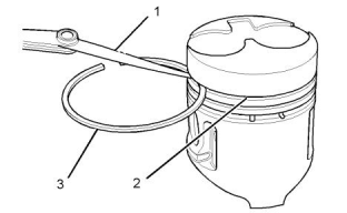
1. Clean all carbon from the top of the cylinder bores.
2. Place each piston ring (2) in the cylinder bore.
1. Remove the piston rings and clean the grooves
and the piston rings.
3. Use a suitable feeler gauge (1) to measure piston
ring end gap. Refer to Specifications, “Piston and
Rings” for the dimensions.
Note: The coil spring must be removed from the oil
control ring before the gap of the oil control ring is
measured.
i02193842
Connecting Rod - Inspect
This procedure determines the following
characteristics of the connecting rod:
• The distortion of the connecting rod
Illustration 83
g01109213
• The parallel alignment of the bores of the
connecting rod
(1) Feeler gauge
(2) Piston grooves
(3) Piston ring
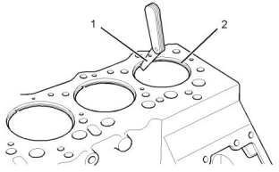
2. Fit new piston rings (3) in the piston grooves (2).
3. Check the clearance for the piston ring by placing a
suitable feeler gauge (1) between piston groove (2)
and the top of piston ring (3). Refer to
Specifications, “Piston and Rings” for the
dimensions.
Note: On 403D-15T, 404D-22Tand 404D-22TA
engines, the pistons have a tapered top groove and
the piston ring is wedged. The clearance for the top
piston ring cannot be checked by the above method
when this occurs.
Inspect the Piston Ring End Gap
This document is printed from SPI². Not for RESALE
![]()
![]()
![]()
![]()
![]()
76
KENR9144
Basic Engine
Connecting rod bearings are available with a smaller
inside diameter than the original size bearings. These
bearings are for crankshafts that have been ground.
i01748792
Main Bearings - Inspect
Check the main bearings for wear or other damage.
Replace both halves of the bearings and check the
condition of the other bearings if a main bearing is
worn or damaged.
Main bearings are available with a smaller inside
diameter than the original size bearings. These
bearings are for main bearing journals that have been
ground.
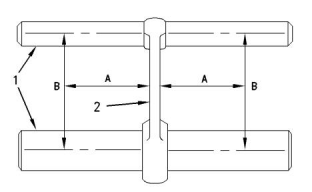
Illustration 85
g00690891
Inspection of the connecting rod parallel alignment.
(1) Measuring pins
(2) Connecting rod
(A) Measure the distance 100 mm (3.94 inch) from the connecting
rod.
i02193978
(B) Measure the distance between the center of the bore for the
piston pin bearing and the center of the connecting rod bearing
bore.
Cylinder Block - Inspect
1. Use the appropriate tools in order to measure the
distances for the connecting rod (2).
• Appropriate gauges for measuring distance
• Measuring pins (1)
Note: The connecting rod bearings should be
removed before taking the measurements.
2. Measure the connecting rod for distortion and
parallel alignment between the bores.
The measurements must be taken at distance (A).
Distance (A) has a value of 100 mm (3.94 inch)
from both sides of the connecting rod.
Illustration 86
g00907375
Measure length (B).
Use a straight edge and a feeler gauge to check the
six positions for flatness. Refer to Illustration 86 .
The total difference in measurements of length (B)
from each side should not vary more than
± 0.08 mm (± 0.0031 inch).
Inspect the top of the cylinder block for cracks,
damage, and warpage.
3. Inspect the piston pin bearing and the piston pin for
wear and other damage.
Inspect each cylinder bore. There should be no
scoring, rust or corrosion. Use a suitable gauge in
order to measure each cylinder bore. Measure the
area of each cylinder bore that is in contact with the
top, middle and bottom piston rings. Each cylinder
bore should be measured at 90 degrees to the
crankshaft.
4. Measure the clearance of the piston pin in the
piston pin bearing. Refer to Specifications,
“Connecting Rod” for clearance dimensions.
i01748770
NOTICE
The flex-hone process must not be used on these
engines.
Connecting Rod Bearings -
Inspect
If the cylinder bores exceed the service limit, the
cylinder block must be renewed. Refer to
Specifications, “Cylinder Block” for the bore
diameters and tolerances.
Check the connecting rod bearings and the
connecting rod bearing journal for wear or other
damage.
This document is printed from SPI². Not for RESALE
![]()
![]()
![]()
![]()
![]()
![]()
![]()
KENR9144
77
Basic Engine
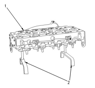
i04904653
Cylinder Head - Inspect
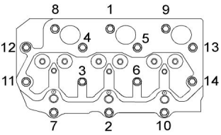
Illustration 87
g01317351
Bolt tightening sequence for the 403F-15T engines
Illustration 89
g00842292
Typical example
4. Put the cylinder head (1) on suitable supports (2).
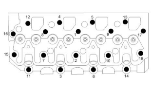
Illustration 88
g01109567
Bolt tightening sequence for the 404D-22, and 404D-
22T engines
Illustration 90
g00907448
1. Remove the bolts in the cylinder head in the
reverse sequence that is shown in Illustrations 87
and 88 .
Typical example
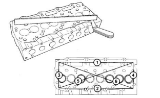
5. Use a straight edge and a feeler gauge to check
the six positions of the cylinder head for distortion.
Refer to Specifications, “Cylinder Head” for the
requirements of flatness.
Remove the cylinder head from the engine.
2. Clean the cylinder head thoroughly. Ensure that the
contact surface of the cylinder head and the
contact surface of the cylinder block are clean,
smooth, and flat.
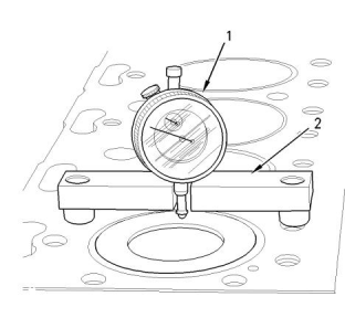
i02194219
Piston Height - Inspect
3. Inspect the bottom surface of the cylinder head for
pitting, corrosion, and cracks. Inspect the area
around the valve seats and the holes for the fuel
injectors.
Table 8
Required Tools
Part Number
21825617
21825496
Part Description
Dial gauge
Qty
1
Dial gauge holder
1
This document is printed from SPI². Not for RESALE
![]()
![]()
![]()
![]()
![]()
![]()
![]()
![]()
![]()
![]()
78
KENR9144
Basic Engine
If the height of the piston above the cylinder block is
not within the tolerance that is given in the
Specifications Module, “Piston and Rings”, the
bearing for the piston pin must be checked. Refer to
Testing and Adjusting, “Connecting Rod - Inspect”. If
any of the following components are replaced or
remachined, the piston height above the cylinder
block must be measured:
3. Position the dial gauge holder (2) and the dial
gauge (1) in order to measure the piston height
above the cylinder block. Slowly rotate the
crankshaft in order to determine when the piston is
at the highest position. Record this dimension.
Compare this dimension with the dimensions that
are given in Specifications, “Cylinder Head”.
• Crankshaft
i02194222
• Cylinder head
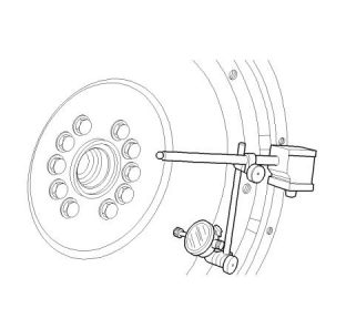
Flywheel - Inspect
• Connecting rod
• Bearing for the piston pin
Alignment of the Flywheel Face
The correct piston height must be maintained in order
to ensure that the engine conforms to the standards
for emissions.
Note: The top of the piston must not be machined. If
the original piston is installed, be sure that the original
piston is assembled to the correct connecting rod and
installed in the original cylinder.
Illustration 92
g00987751
1. Install the dial indicator. Refer to Illustration 92 .
2. Set the pointer of the dial indicator to 0 mm
(0 inch).
Illustration 91
g00953648
3. Turn the flywheel. Read the dial indicator for every
(1) Dial gauge
(2) Dial gauge holder
90 degrees.
Note: During the check, keep the crankshaft pressed
toward the front of the engine in order to remove any
end clearance.
1. Use the dial gauge (1) and the dial gauge holder
(2) in order to measure the piston height above the
cylinder block. Use the cylinder block face to zero
the dial gauge (1).
4. Calculate the difference between the lowest
measurement and the highest measurement of the
four locations. This difference must not be greater
than 0.03 mm (0.001 inch) for every 25 mm
(1.0 inch) of the radius of the flywheel. The radius
of the flywheel is measured from the axis of the
crankshaft to the contact point of the dial indicator.
2. Rotate the crankshaft until the piston is at the
approximate top center.
This document is printed from SPI². Not for RESALE
![]()
![]()
![]()
![]()
![]()
KENR9144
79
Basic Engine
Flywheel Runout
Face Runout (Axial Eccentricity)of
the Flywheel Housing
Illustration 94
g00285931
21825617 Dial Indicator Group
1. Fasten a dial indicator to the flywheel so the anvil
of the dial indicator will contact the face of the
flywheel housing.
Illustration 93
g00987752
1. Install the dial indicator. Refer to Illustration 93 .
2. Put a force on the crankshaft toward the rear
before the dial indicator is read at each point.
2. Set the pointer of the dial indicator to 0 mm
(0 inch).
3. Turn the flywheel. Read the dial indicator for every
90 degrees.
4. Calculate the difference between the lowest
measurement and the highest measurement of the
four locations. This difference must not be greater
than 0.20 mm (0.008 inch).
i05191413
Flywheel Housing - Inspect
Illustration 95
g00285932
Table 9
Checking face runout of the flywheel housing
Required Tools
Part
Number
3. Turn the flywheel while the dial indicator is set at
0.0 mm (0.00 inch) at location (A). Read the dial
indicator at locations (B), (C), and (D).
Part Name
Qty
21825617
Dial Indicator Group
1
4. The difference between the lower measurements
and the higher measurements that are performed
at all four points must not be more than 0.20 mm
(0.008 inch) for an “SAE 5” flywheel housing. The
difference between the lower measurements and
the higher measurements that are performed at all
four points must not be more than 0.23 mm
(0.009 inch) for an “SAE 4” flywheel housing.
These measurements are the maximum
permissible face runout (axial eccentricity) of the
flywheel housings.
This document is printed from SPI². Not for RESALE
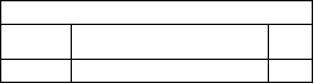
![]()
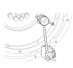
![]()
![]()
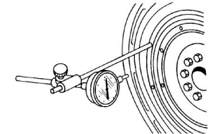
![]()
![]()
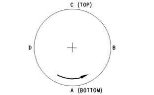
![]()
![]()
80
KENR9144
Basic Engine
Bore Runout (Radial Eccentricity)
of the Flywheel Housing
i02617095
Gear Group - Inspect
Illustration 96
g00285934
21825617 Dial Indicator Group
Illustration 98
g00907566
1. Fasten a dial indicator to the flywheel so the anvil
of the dial indicator will contact the bore of the
flywheel housing.
1. Inspect the gears for wear or damage. If one or
more of the gears are worn or damaged, use new
parts for replacement.
2. Measure the backlash of the gears with a feeler
gauge. Refer to Illustration 98 . If the backlash
measurement is greater than the maximum, install
new gears.
Note: Refer to Specifications, “Gear Group (Front)”
for the minimum and maximum backlash
measurements.
Illustration 97
g00285932
Checking bore runout of the flywheel housing
2. Turn the flywheel while the dial indicator is set at
0.0 mm (0.00 inch) at location (A). Read the dial
indicator at locations (B), (C), and (D).
3. The difference between the lower measurements
and the higher measurements that are performed
at all four points must not be more than 0.20 mm
(0.008 inch) for an “SAE 5” flywheel housing. The
difference between the lower measurements and
the higher measurements that are performed at all
four points must not be more than 0.23 mm
(0.009 inch) for an “SAE 4” flywheel housing.
These measurements are the maximum
permissible bore runout (radial eccentricity) of the
flywheel housings.
This document is printed from SPI². Not for RESALE
![]()
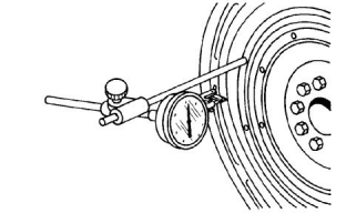
![]()
![]()

![]()
![]()
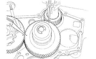
![]()
![]()
KENR9144
81
Electrical System
Electrical System
i02195377
Alternator - Test
1. Put the positive lead “+” of a suitable multimeter
on the “Bat” terminal of the alternator. Put the
negative “-” lead on the ground terminal or on the
frame of the alternator. Put a suitable ammeter
around the positive output wire of the alternator.
2. Turn off all electrical accessories. Turn off the fuel
to the engine. Operate the starter motor for 30
seconds. Wait for two minutes in order to cool the
starter motor. If the electrical system appears to
operate correctly, operate the starter motor again
for 30 seconds.
Note: Operating the starter motor for 30 seconds
partially discharges the batteries in order to do a
charging test. If the battery has a low charge, do not
perform this step. Jump start the engine or charge the
battery before the engine is started.
3. Start the engine and run the engine at high idle.
4. Check the output current of the alternator. The
initial charging current should be equal to the
minimum full load current or greater than the
minimum full load current. Refer to Specifications,
“Alternator and Regulator” for the correct minimum
full load current.
Table 10
Fault Conditions And Possible Causes
Current At Start-up
The Voltage Is Below Specifica- The Voltage Is Within Specifica- The Voltage Is Above Specifica-
tions After 10 Minutes.
tions After 10 Minutes.
tions After 10 Minutes.
Less than the specifications
Replace the alternator. Check the Turn on all accessories. If the volt-
-
circuit of the ignition switch.
Replace the alternator.
age decreases below the specifi-
cations, replace the alternator.
Decreases after matching
specifications
The alternator and the battery
match the specifications. Turn on
all accessories in order to verify
that the voltage stays within
specifications.
Replace the alternator.
The voltage consistentlyex-
ceeds specifications.
Test the battery. Test the alternator The alternator operates within the Replace the alternator. Inspect the
again. specifications. Test the battery. battery for damage.
6. After ten minutes of engine operation, the charging
current should decrease to approximately 10
amperes. The actual length of time for the
decrease to 10 amperes depends on the following
conditions:
5. After approximately ten minutes of operating the
engine at high idle, the output voltage of the
alternator should be 14.0 ± 0.5 volts. Refer to the
Fault Conditions And Possible Causes in Table 10
.
This document is printed from SPI². Not for RESALE

![]()
82
KENR9144
Electrical System
• The battery charge
Whenever it is possible, test the charging unit and the
voltage regulator on the engine. This test will use
wiring and components that are a permanent part of
the system. Off-engine testing or bench testing will
give a test of the charging unit and voltage regulator
operation. This testing will give an indication of
needed repair. After repairs are made, perform a test
in order to prove that the units have been repaired to
the original condition of operation.
• The ambient temperature
• The rpm of the engine
Refer to the Fault Conditions And Possible Causes
in Table 10 .
i01899136
Alternator Regulator
Battery - Test
The charging rate of the alternator should be checked
when an alternator is charging the battery too much
or not charging the battery enough.
Most of the tests of the electrical system can be done
on the engine. The wiring insulation must be in good
condition. The wire and cable connections must be
clean, and both components must be tight.
Alternator output should be 14 ± 0.5 volt. No
adjustment can be made in order to change the rate
of charge on the alternator regulator. If the rate of
charge is not correct, a replacement of the regulator
is necessary. For individual alternator output, refer to
Specification, “Alternator and Regulator”.
Never disconnect any charging unit circuit or bat-
tery circuit cable from the battery when the charg-
ing unit is operated. A spark can cause an
explosion from the flammable vapor mixture of
hydrogen and oxygen that is released from the
electrolyte through the battery outlets. Injury to
personnel can be the result.
i02196186
Coolant Temperature Switch -
Test
This procedure tests the coolant temperature switch
for correct operation. Perform this procedure when
the engine is running.
The battery circuit is an electrical load on the
charging unit. The load is variable because of the
condition of the charge in the battery.
1. Use a suitable digital multimeter to measure the
resistance of the coolant temperature switch.
When the temperature of the coolant is 50 °C
(122 °F) or less, disconnect the wire connector
from the coolant temperature switch.
NOTICE
The charging unit will be damaged if the connections
between the battery and the charging unit are broken
while the battery is being charged. Damage occurs
because the load from the battery is lost and because
there is an increase in charging voltage. High voltage
will damage the charging unit, the regulator, and other
electrical components.
2. Place one lead of the multimeter on the connector
of the coolant temperature switch. Place the other
lead of the multimeter on a ground for the coolant
temperature switch.
The correct procedures to test the battery can be
found in the manual that is supplied by the OEM.
Measure the resistance. The resistance should be
54 ± 2 ohms.
3. Repeat the previous step when the temperature of
the coolant is approximately 120 °C (248 °F). The
resistance should not be less than 15 ohms.
i02196181
Charging System - Test
4. If the resistance through the coolant temperature
switch is not within the given resistances, replace
the coolant temperature switch.
The condition of charge in the battery at each regular
inspection will show if the charging system is
operating correctly. A repair is necessary when the
battery is constantly in a low condition of charge or a
large amount of water is needed. There are no
adjustments on maintenance free batteries. A large
amount of water would be more than one ounce of
water per cell per week or per every 100 service
hours.
i02196199
Electric Starting System - Test
Use a suitable multimeter in the “DC volts” range to
find starting system components which do not
function.
This document is printed from SPI². Not for RESALE
![]()
![]()
![]()
![]()
![]()
KENR9144
83
Electrical System
Move the start control switch in order to activate the
starter solenoid. The operation of the starter solenoid
can be heard as the pinion of the starter motor is
engaged with the ring gear on the engine flywheel.
If the circuit is correct, replace the engine oil
pressure switch. If the circuit is repaired or if the
engine oil pressure switch or warning lamp are
replaced, repeat this Step in order to ensure that
the warning light turns on.
If the solenoid for the starter motor will not operate, it
is possible that the current from the battery did not
reach the solenoid. Fasten one lead of the multimeter
to the connection (terminal) for the battery cable on
the solenoid. Connect the other lead to a good
ground. A zero reading indicates that there is a
broken circuit from the battery. More testing is
necessary when there is a voltage reading on the
multimeter.
Note: The engine oil pressure switch may be
mounted on either the cylinder block or the valve
mechanism cover.
2. Remove the engine oil pressure switch from the
cylinder block or from the valve mechanism cover.
Disconnect the wire connector on the wiring
harness from the engine oil pressure switch. Use a
12 volt battery as a power source. Connect the
terminals of the battery, the engine oil pressure
switch and the leads of a suitable digital multimeter
in series. Measure the current through the engine
oil pressure switch.
The operation of the solenoid also closes the electric
circuit to the starter motor. Connect one lead of the
multimeter to the solenoid connection (terminal) that
is fastened to the starter motor. Connect the other
lead to a good ground. Activate the starter solenoid
and look at the multimeter. A voltage reading of the
battery shows that the problem is in the starter motor.
The starter motor must be removed for further testing.
A zero reading on the multimeter shows that the
solenoid contacts do not close. This indicates the
need for repair to the solenoid, or to the clearance for
the starter motor pinion.
3. The current should be 0.30 to 0.40 amperes. If the
current through the engine oil pressure switch is
greater than 0.42 amperes, replace the engine oil
pressure switch.
Perform a test. Fasten one multimeter lead to the
connection (terminal) for the small wire at the
solenoid and fasten the other lead to the ground.
Look at the multimeter and activate the starting
solenoid. A voltage reading shows that the problem is
in the solenoid. A zero reading indicates that the
problem is in the start switch or the wires for the start
switch.
i02196363
Fuel Shutoff Solenoid - Test
Fasten one multimeter lead to the start switch at the
connection (terminal) for the wire from the battery.
Fasten the other lead to a good ground. A zero
reading indicates a broken circuit from the battery.
Check of the circuit breaker and wiring. If there is a
voltage reading, the problem is in the start switch or in
the wires for the start switch.
A starter motor that operates too slowly can have an
overload due to excessive friction in the engine that is
being started. Slow operation of the starter motor can
also be caused by a short circuit, loose connections,
and/or dirt in the starter motor.
i02196230
Engine Oil Pressure Switch -
Test
This procedure tests the engine oil pressure switch
for correct operation.
Illustration 99
g01115662
(1) Positive “+” lead
(2) Electrical connector
(3) Plunger
(4) Body of the fuel shutoff solenoid
(5) Negative “−” lead
1. Turn the ignition switch to the ON, but do not start
the engine. The warning light for low engine oil
pressure should turn on.
This procedure tests the fuel shutoff solenoid for
correct operation.
If the warning light does not turn on, check the
electrical circuit to the warning light and the engine
oil pressure switch for shorts or an open circuit.
Check the bulb for the warning light for damage.
This document is printed from SPI². Not for RESALE
![]()
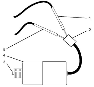
![]()
![]()
84
KENR9144
Electrical System
1. Remove the fuel shutoff solenoid from the engine.
Refer to Disassembly and Assembly, “Fuel Shutoff
Solenoid - Remove and Install”.
1. Connect a suitable test light between a ground and
the terminal of the glow plug (4). Choose the glow
plug that is farthest away from the battery. Turn the
starting aid switch to the ON position.
2. Use a 12 volt battery as a power source. Connect
the lead from the battery positive terminal (1) to
one of the pins in the electrical connector (2) on
the fuel shutoff solenoid. Connect the lead from the
battery negative terminal (5) to the remaining pin in
the electrical connector (2) on the fuel shutoff
solenoid.
If the circuit is correct, the test light should turn on.
If the test light does not turn on, inspect the circuit
for loose connections, broken wires, and other
damage.
2. Loosen the nut (1) on each glow plug and then
disconnect the connectors (3) from the glow plugs
(4).
The plunger (3) on the fuel shutoff solenoid (4)will
extend the maximum distance when the leads are
connected.
3. Use a suitable digital multimeter to measure the
resistance between the electrical terminal of the
glow plug (4) and ground. The point for the ground
should be as close to the glow plug as possible.
If the plunger does not move or if the plunger does
not extend the maximum distance, replace the fuel
shutoff solenoid.
3. Use a suitable digital multimeter to measure the
current through the fuel shutoff solenoid. Connect
the battery, the fuel shutoff solenoid, and the leads
of the multimeter in series.
Maximum resistance for the glow plugs. ....... 1.0 ohm
4. Connect the test light to the positive terminal of the
battery and to the electrical terminal of the glow
plug (4). If the light turns on, the continuity in the
glow plug is correct.
The current should be 1.0 ± 0.1 amperes. If the
current is not within this tolerance, replace the fuel
shutoff solenoid.
If the light does not turn on, replace the glow plug.
Repeat this step for each glow plug.
4. Install the fuel shutoff solenoid on the engine. Refer
to Disassembly and Assembly, “Fuel Shutoff
Solenoid - Remove and Install”.
5. Install the connector (3) on each glow plug (4) and
tighten the nut (1).
i05191119
Glow Plug Circuit
Glow Plugs - Test
1. Disconnect the power supply cable from the
connector (3). Loosen the nut (1) and remove the
connector (3) from the electrical terminal of the
glow plug (4).
2. Connect the leads of a suitable ammeter between
the power supply cable and the terminal of a glow
plug and then connect the leads of the digital
multimeter between the terminal of the glow plug
and a ground. Turn on the starting aid switch.
Observe the amperage reading of the ammeter
and the voltage reading on the multimeter.
403F-15T, 404F-22, and 404F-22T
Maximum current through the glow plug ....... 11 A
Illustration 100
g01109557
Current through the glow plug after 6 seconds
......................................................................8.5 A
Typical example
(1) Nut
The voltage should not drop more than 0.5 V.
Perform step 2 for each glow plug.
(2) Washer
(3) Connector
(4) Glow plug
3. If the multimeter reading is below the specified
amperes, the glow plug should be replaced. If
there is no reading, replace the glow plug.
Continuity Test
This document is printed from SPI². Not for RESALE
![]()
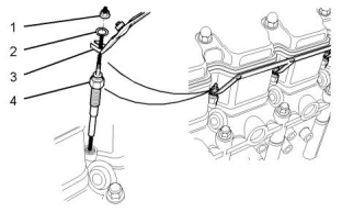
![]()
![]()
KENR9144
85
Electrical System
If the voltage reading of the multimeter is zero,
inspect the starting aid switch and the power
supply for faulty components and loose
connections.
4. When the tests are complete, install the connector
(3) to the terminal of each of the glow plugs (4) and
tighten the nut (1). Connect the cable for the power
supply to the glow plugs.
This document is printed from SPI². Not for RESALE
![]()
86
KENR9144
Index Section
Index
A
Cleaning Procedure..................................... 59
Reset the Engine Ash Model ....................... 60
Air in Fuel - Test............................................... 46
Air Inlet and Exhaust System......................35, 59
Crankcase Breather..................................... 37
Cylinder Head And Valves........................... 36
NOx Reduction System (NRS) - Turbocharged
Engines...................................................... 36
Turbocharger................................................ 35
Air Inlet and Exhaust System - Inspect............ 59
Alternator - Test ............................................... 81
E
Electric Starting System - Test......................... 82
Electrical System........................................43, 81
Charging System Components.................... 44
Engine Electrical System............................. 43
Other Components....................................... 45
Starting System Components...................... 44
Electronic Control System Components.......... 14
Block diagram for the 403F-15T engine...... 14
Block diagram for the 404F-22 engine........ 16
Block diagram for the 404F-22T engine...... 17
Diagnostic Codes......................................... 27
ECM............................................................. 27
Pressure Sensors and Switches.................. 30
Sensor Locations for the Clean Emissions
B
Basic Engine...............................................42, 75
Cylinder Head and Block ............................. 42
Pistons and Connecting Rods ..................... 42
Timing Gear Case and Gears...................... 43
Battery - Test.................................................... 82
Module ....................................................... 26
Sensor Locations for the Engine.................. 17
Speed Sensors ............................................ 27
Temperature Sensors................................... 31
Engine Oil Pressure - Test............................... 67
Engine Oil Pressure Switch - Test ................... 83
Engine Oil Pump - Inspect............................... 67
Engine Valve Lash - Inspect/Adjust................. 62
Valve Lash Adjustment ................................ 62
Valve Lash Setting....................................... 62
Excessive Bearing Wear - Inspect................... 68
Excessive Engine Oil Consumption - Inspect.. 69
Engine Oil Leaks into the Combustion Area of
the Cylinders.............................................. 69
Engine Oil Leaks on the Outside of the Engine
................................................................... 69
Exhaust Cooler (NRS) - Test (If Equipped)...... 61
C
Charging System - Test ................................... 82
Alternator Regulator..................................... 82
Clean Emissions Module................................. 37
Air System for the Clean Emissions Module
................................................................... 40
Electronic Controls....................................... 40
Fuel System for the Clean Emissions Module
................................................................... 40
Soot Level Outputs ...................................... 39
Compression - Test.......................................... 62
Compression................................................ 62
Connecting Rod - Inspect................................ 75
Connecting Rod Bearings - Inspect................. 76
Coolant Temperature Switch - Test.................. 82
Cooling System ..........................................41, 70
Cooling System - Check (Overheating)........... 70
Cooling System - Inspect................................. 71
Cooling System - Test...................................... 71
Checking the Filler Cap................................ 72
Testing The Radiator And Cooling System For
Leaks.......................................................... 73
Cylinder Block - Inspect................................... 76
Cylinder Head - Inspect................................... 77
F
Finding Top Center Position for No. 1 Piston... 47
Flywheel - Inspect............................................ 78
Alignment of the Flywheel Face................... 78
Flywheel Runout.......................................... 79
Flywheel Housing - Inspect ............................. 79
Bore Runout (Radial Eccentricity) of the
Flywheel Housing....................................... 80
Face Runout (Axial Eccentricity) of the
D
Flywheel Housing....................................... 79
Diesel Particulate Filter - Clean....................... 59
This document is printed from SPI². Not for RESALE
![]()
KENR9144
87
Index Section
Fuel Injection Timing - Check .......................... 47
Fuel Injector - Test ........................................... 49
Inspection and Cleaning of the Fuel Injectors
................................................................... 49
Leakage Test................................................ 49
Pressure Test............................................... 50
Test for the Nozzle Spray Pattern ................ 51
Fuel Quality - Test............................................ 52
Fuel Shutoff Solenoid - Test............................. 83
Fuel System................................................31, 46
Fuel Injection Nozzles.................................. 34
Fuel Injection Pump ..................................... 34
Fuel Transfer Pump ..................................... 35
General Operation of the Fuel System......... 31
Glow Plugs................................................... 35
Governor...................................................... 33
Fuel System - Inspect...................................... 46
Fuel System - Prime........................................ 52
Fuel Transfer Pump - Test ............................... 48
M
Main Bearings - Inspect................................... 76
P
Piston Height - Inspect..................................... 77
Piston Ring Groove - Inspect........................... 75
Inspect the Clearance of the Piston Ring..... 75
Inspect the Piston and the Piston Rings ...... 75
Inspect the Piston Ring End Gap................. 75
S
Systems Operation Section............................... 4
T
Table of Contents............................................... 3
Testing and Adjusting Section ......................... 46
G
V
Gear Group - Inspect....................................... 80
Gear Group (Front) - Time............................... 52
General Information........................................... 4
403F-15T ....................................................... 5
404F-22.......................................................... 6
404F-22T ....................................................... 7
Engine Description......................................... 4
Engine Model Views ...................................... 4
Loose Components for the Engine .............. 10
Glossary of Electronic Control Terms .............. 10
Glow Plugs - Test............................................. 84
Continuity Test ............................................. 84
Glow Plug Circuit ......................................... 84
Governor - Adjust............................................. 52
Final Installation of the New Front Housing
Valve Depth - Inspect....................................... 65
Valve Guide - Inspect....................................... 66
W
Wastegate - Test.............................................. 60
Inspection of the Wastegate......................... 60
Water Pump - Inspect...................................... 73
Water Temperature Regulator - Test................ 73
Introduction.................................................. 73
Test Procedure............................................. 73
................................................................... 56
Record the Governor Settings ..................... 53
Removal of the Old Front Housing............... 53
Setting the Fuel Screw ................................ 56
Setting the New Front Housing.................... 55
I
Important Safety Information............................. 2
L
Lubrication System.....................................40, 67
This document is printed from SPI². Not for RESALE
![]()
©2013 Perkins Engines Company Limited
All Rights Reserved
This document is printed from SPI². Not for RESALE