 English
 Espaol
 Franais
 阿拉伯
阿拉伯 中文
中文 Deutsch
 Italiano
 Português
 日本
日本 韩国
韩国 български
 hrvatski
 esky
esky Dansk
Dansk Nederlands
 suomi
suomi Ελληνικ
 印度
印度 norsk
norsk Polski
 Roman
Roman русский
 Svenska
珀金斯402/403F-11操作保养供应商,珀金斯402/403F-11操作保养技术价格规格咨询服务,珀金斯402/403F-11操作保养零配件供应,珀金斯402/403F-11操作保养售后服务中心,珀金斯402/403F-11操作保养,珀金斯402/403F-11操作保养详细的技术参数,

产品中心
珀金斯402/403F-11操作保养(英文)二
详细描述
Buildup – Compounds, elements, corrosive
chemicals, and salt can damage some components.
Altitude – Problems can arise when the engine is
operated at altitudes that are higher than the intended
settings for that application. Necessary adjustments
should be made.
Incorrect Operating Procedures
• Extended operation at low idle
• Frequent hot shutdowns
• Operating at excessive loads
• Operating at excessive speeds
• Operating outside the intended application
Incorrect Maintenance Procedures
• Extending the maintenance intervals
• Failure to use recommended fuel, lubricants, and
coolant/antifreeze
This document is printed from SPI². Not for RESALE
![]()
54
SEBU9064
Maintenance Recommendations
Maintenance Interval Schedule
i05335244
“Engine Air Cleaner Element (Single Element) -
Inspect/Clean/Replace”...........................................66
“Engine Oil and Filter - Change”..............................69
“Hoses and Clamps - Inspect/Replace”...................78
“Radiator - Clean” ....................................................79
MaintenanceInterval Schedule
When Required
“Battery - Replace”...................................................57
“Engine - Clean”.......................................................64
Every 1000 Service Hours
“Alternator and Fan Belts - Replace”.......................56
“Engine Valve Lash - Check”...................................71
“Engine Air Cleaner Element (Dual Element) -
Inspect/Clean/Replace”...........................................64
Every 2000 Service Hours
“Engine Air Cleaner Element (Single Element) -
Inspect/Clean/Replace”...........................................66
“Alternator - Inspect”................................................54
“Engine Crankcase Breather - Replace” .................68
“Engine Mounts - Inspect” .......................................68
“Starting Motor - Inspect”.........................................80
“Fuel System - Prime”..............................................74
Daily
“Coolant Level - Check”...........................................61
“Driven Equipment - Check” ....................................63
“Engine Air Cleaner Service Indicator - Inspect”.....67
“Engine Air Precleaner - Check/Clean”...................67
“Engine Oil Level - Check”.......................................68
Every 3000 Service Hours
“Coolant Temperature Regulator - Replace” ...........62
“Fuel Injector - Test/Change”...................................73
“Water Pump - Inspect”............................................81
“Fuel System Primary Filter/Water Separator -
Drain”.......................................................................75
Every 3000 Service Hours or 2
Years
“Walk-Around Inspection”........................................80
“Coolant (Commercial Heavy-Duty) - Change” .......58
Every 50 Service Hours or Weekly
Every 12 000 Service Hours or 6
Years
“Fuel Tank Water and Sediment - Drain”.................78
Every 250 Service Hours or 6
Months
“Coolant (ELC) - Change”........................................59
Commissioning
“Alternator and Fan Belts - Inspect/Adjust” .............55
“Fan Clearance - Check” .........................................72
Every 500 Service Hours
“Fan Clearance - Check” .........................................72
“Fuel Filter (In-Line) - Replace”................................72
“Fuel System Primary Filter - Replace” ...................74
“Fuel System Secondary Filter - Replace” ..............76
i02322311
Alternator - Inspect
Perkins recommends a scheduled inspection of the
alternator. Inspect the alternator for loose
connections and correct battery charging. Check the
ammeter (if equipped) during engine operation in
order to ensure correct battery performance and/or
correct performance of the electrical system. Make
repairs, as required.
Every 500 Service Hours or 1 Year
“Battery Electrolyte Level - Check”..........................57
“Cooling System Supplemental Coolant Additive
(SCA) - Test/Add”.....................................................63
“Engine Air Cleaner Element (Dual Element) -
Inspect/Clean/Replace”...........................................64
This document is printed from SPI². Not for RESALE
![]()
SEBU9064
55
Maintenance Recommendations
Alternator and Fan Belts - Inspect/Adjust
Check the alternator and the battery charger for
correct operation. If the batteries are correctly
charged, the ammeter reading should be very near
zero. All batteries should be kept charged. The
batteries should be kept warm because temperature
affects the cranking power. If the battery is too cold,
the battery will not crank the engine. When the engine
is not run for long periods of time or if the engine is
run for short periods, the batteries may not fully
charge. A battery with a low charge will freeze more
easily than a battery with a full charge.
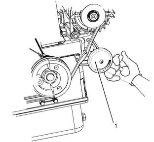
Install the gauge (1) at the center of the belt between
the alternator and the crankshaft pulley and check the
belt tension. The correct tension for a new belt is
400 N (90 lb) to 489 N (110 lb). The correct tension
for a used belt that has been in operation for 30
minutes or more at the rated speed is 267 N (60 lb) to
356 N (80 lb).
If twin belts are installed, check and adjust the
tension on both belts.
Adjustment
i05341153
Alternator and Fan Belts -
Inspect/Adjust
Inspection
To maximize the engine performance, inspect the
belts for wear and for cracking. Replace belts that are
worn or damaged.
For applications that require multiple drive belts,
replace the belts in matched sets. Replacing only one
belt of a matched set will cause the new belt to carry
more load because the older belt is stretched. The
additional load on the new belt could cause the new
belt to break.
If the belts are too loose, vibration causes
unnecessary wear on the belts and pulleys. Loose
belts may slip enough to cause overheating.
Illustration 25
g03383151
To check accurately the belt tension, a suitable gauge
should be used.
Illustration 26
g03383155
Illustration 24
g03383147
Typical example
(1) Burroughs Gauge
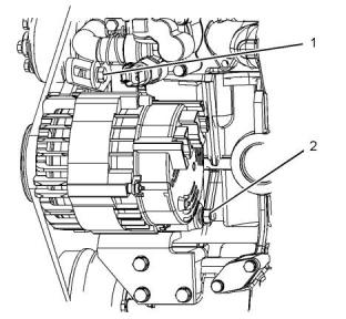
1. Loosen adjusting bolt (1) and mounting bolt and
nut (2). Loosen bolt (3).
This document is printed from SPI². Not for RESALE
![]()
![]()
![]()
![]()
![]()
![]()
![]()
56
SEBU9064
Maintenance Recommendations
Alternator and Fan Belts - Replace
2. Move the alternator in order to increase or
decrease the belt tension.
3. Tighten adjusting bolt (1) and tighten mounting
bolts and nut (2). Tighten bolt (3). Tighten all fixing
to a torque of 25 N·m (221 lb in)
i05341723
Alternator and Fan Belts -
Replace
For applications that require multiple drive belts,
replace the belts in matched sets. Replacing only one
belt of a matched set will cause the new belt to carry
more load because the older belt is stretched. The
additional load on the new belt could cause the new
belt to break.
Note: When new belts are installed, check the belt
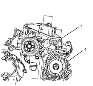
Illustration 28
g03383666
tension again after 20 hours of engine operation.
Typical example
Removal and InstallationProcedure
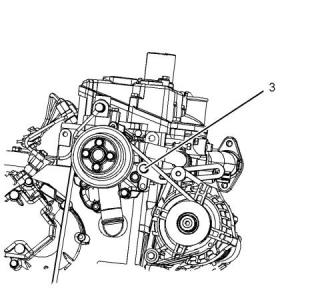
1. Loosen adjusting bolt (1) and mounting bolt and
nut (2). Loosen bolt (3).
Refer to the original equipment manufacture for
removal and installation of the fan guards.
2. Push the alternator (4) towards the engine.
Note: If the belt is to be reused, mark the belt in order
to show direction of rotation.
Illustration 27
g03383665
Typical example
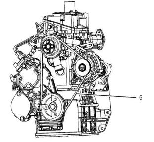
Illustration 29
g03383667
Typical example
3. Remove the belt (5).
This document is printed from SPI². Not for RESALE
![]()

![]()
![]()
![]()
![]()
![]()
![]()
SEBU9064
57
Maintenance Recommendations
Battery - Replace
4. Install new belt (5) and adjust the alternator to the
required tension.
Note: Always recycle a battery. Never discard a
battery. Dispose of used batteries to an appropriate
recycling facility.
5. Tighten bolt (1) and tighten bolt and nut (2). Tighten
bolt (3). Tighten all bolts and nuts to a torque of
25 N·m (221 lb in).
5. Remove the used battery.
6. Install the new battery.
Refer to this Operation and Maintenance Manual,
“Alternator and Fan Belts - Inspect/Adjust” for the
tension of the belt.
Note: Before the cables are connected, ensure that
the engine start switch is OFF.
7. Connect the cable from the starting motor to the
POSITIVE “+” battery terminal.
i02322315
Battery - Replace
8. Connect the NEGATIVE “-” cable to the
NEGATIVE “-” battery terminal.
i02747977
Battery Electrolyte Level -
Check
Batteries give off combustible gases which can
explode. A spark can cause the combustible
gases to ignite. This can result in severe personal
injury or death.
When the engine is not run for long periods of time or
when the engine is run for short periods, the batteries
may not fully recharge. Ensure a full charge in order
to help prevent the battery from freezing. If batteries
are correctly charged, the ammeter reading should be
very near zero, when the engine is in operation.
Ensure proper ventilation for batteries that are in
an enclosure. Follow the proper procedures in or-
der to help prevent electrical arcs and/or sparks
near batteries. Do not smoke when batteries are
serviced.
All lead-acid batteries contain sulfuric acid which
can burn the skin and clothing. Always wear a
face shield and protective clothing when working
on or near batteries.
The battery cables or the batteries should not be
removed with the battery cover in place. The bat-
tery cover should be removed before any servic-
ing is attempted.
Removing the battery cables or the batteries with
the cover in place may cause a battery explosion
resulting in personal injury.
1. Remove the filler caps. Maintain the electrolyte
level to the “FULL” mark on the battery.
If the addition of water is necessary, use distilled
water. If distilled water is not available use clean
water that is low in minerals. Do not use artificially
softened water.
1. Switch the engine to the OFF position. Remove all
electrical loads.
2. Turn off any battery chargers. Disconnect any
battery chargers.
2. Check the condition of the electrolyte with a
suitable battery tester.
3. The NEGATIVE “-” cable connects the NEGATIVE
“-” battery terminal to the NEGATIVE “-” terminal
on the starting motor. Disconnect the cable from
the NEGATIVE “-” battery terminal.
3. Install the caps.
4. Keep the batteries clean.
Clean the battery case with one of the following
cleaning solutions:
4. The POSITIVE “+” cable connects the POSITIVE
“+” battery terminal to the POSITIVE “+” terminal
on the starting motor. Disconnect the cable from
the POSITIVE “+” battery terminal.
• Use a solution of 0.1 kg (0.2 lb) baking soda
and 1 L (1 qt) of clean water.
• Use a solution of ammonium hydroxide .
Thoroughly rinse the battery case with clean water.
This document is printed from SPI². Not for RESALE
![]()
![]()
![]()
![]()
![]()
![]()
![]()
58
SEBU9064
Maintenance Recommendations
Coolant (Commercial Heavy-Duty) - Change
i05336023
1. Stop the engine and allow the engine to cool.
Loosen the cooling system filler cap slowly in order
to relieve any pressure. Remove the cooling
system filler cap.
Coolant (Commercial Heavy-
Duty) - Change
NOTICE
Care must be taken to ensure that fluids are con-
tained during performance of inspection, mainte-
nance, testing, adjusting and repair of the product. Be
prepared to collect the fluid with suitable containers
before opening any compartment or disassembling
any component containing fluids.
Dispose of all fluids according to Local regulations
and mandates.
NOTICE
Keep all parts clean from contaminants.
Contaminants may cause rapid wear and shortened
component life.
Clean the cooling system and flush the cooling
system before the recommended maintenance
interval if the following conditions exist:
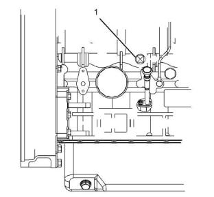
Illustration 30
g03380650
Typical example
• The engine overheats frequently.
• Foaming is observed.
2. Open the drain cock or remove the drain plug (1)
on the engine. Open the drain cock or remove the
drain plug on the radiator.
• The oil has entered the cooling system and the
coolant is contaminated.
Allow the coolant to drain.
• The fuel has entered the cooling system and the
coolant is contaminated.
NOTICE
Dispose of used engine coolant or recycle. Various
methods have been proposed to reclaim used coolant
for reuse in engine cooling systems. The full distilla-
tion procedure is the only method acceptable by Per-
kins to reclaim the coolant.
Note: When the cooling system is cleaned, only
clean water is needed.
Note: Inspect the water pump and the water
temperature regulator after the cooling system has
been drained. This is a good opportunity to replace
the water pump, the water temperature regulator, and
the hoses, if necessary.
For information regarding the disposal and the
recycling of used coolant, consult your Perkins
dealer or your Perkins distributor.
Drain
Flush
1. Flush the cooling system with clean water in order
to remove any debris.
Pressurized System: Hot coolant can cause seri-
ous burns. To open the cooling system filler cap,
stop the engine and wait until the cooling system
components are cool. Loosen the cooling system
pressure cap slowly in order to relieve the
pressure.
2. Close the drain cock or install the drain plug in the
engine. Close the drain cock or install the drain
plug on the radiator.
This document is printed from SPI². Not for RESALE
![]()
![]()
![]()
![]()
![]()
![]()
![]()
![]()
![]()
![]()
![]()
SEBU9064
59
Maintenance Recommendations
Coolant (ELC) - Change
5. Clean the cooling system filler cap. Inspect the
gasket that is on the cooling system filler cap. If the
gasket that is on the cooling system filler cap is
damaged, discard the old cooling system filler cap
and install a new cooling system filler cap. If the
gasket that is on the cooling system filler cap is not
damaged, use a suitable pressurizing pump in
order to pressure test the cooling system filler cap.
The correct pressure for the cooling system filler
cap is stamped on the face of the cooling system
filler cap. If the cooling system filler cap does not
retain the correct pressure, install a new cooling
system filler cap.
NOTICE
Do not fill the cooling system faster than 5 L
(1.3 US gal) per minute to avoid air locks.
Cooling system air locks may result in engine
damage.
3. Fill the cooling system with clean water. Install the
cooling system filler cap.
4. Start and run the engine at low idle until the
temperature reaches 49 to 66 °C (120 to 150 °F).
5. Stop the engine and allow the engine to cool.
Loosen the cooling system filler cap slowly in order
to relieve any pressure. Remove the cooling
system filler cap. Open the drain cock or remove
the drain plug on the engine. Open the drain cock
or remove the drain plug on the radiator. Allow the
water to drain. Flush the cooling system with clean
water.
6. Start the engine. Inspect the cooling system for
leaks and for correct operating temperature.
i05336034
Coolant (ELC) - Change
Fill
NOTICE
1. Close the drain cock or install the drain plug on the
engine. Close the drain cock or install the drain
plug on the radiator.
Care must be taken to ensure that fluids are con-
tained during performance of inspection, mainte-
nance, testing, adjusting and repair of the product. Be
prepared to collect the fluid with suitable containers
before opening any compartment or disassembling
any component containing fluids.
NOTICE
Do not fill the cooling system faster than 5 L
(1.3 US gal) per minute to avoid air locks.
Dispose of all fluids according to Local regulations
and mandates.
Cooling system air locks may result in engine
damage.
NOTICE
Keep all parts clean from contaminants.
2. Fill the cooling system with Commercial Heavy-
Duty Coolant. Add Supplemental Coolant Additive
to the coolant. For the correct amount, refer to the
Operation and Maintenance Manual, “Fluid
Recommendations” topic (Maintenance Section)
for more information on cooling system
specifications. Do not install the cooling system
filler cap.
Contaminants may cause rapid wear and shortened
component life.
Clean the cooling system and flush the cooling
system before the recommended maintenance
interval if the following conditions exist:
• The engine overheats frequently.
• Foaming is observed.
3. Start and run the engine at low idle. Increase the
engine rpm to high idle. Run the engine at high idle
for 1 minute in order to purge the air from the
cavities of the engine block. Stop the engine.
• The oil has entered the cooling system and the
coolant is contaminated.
4. Check the coolant level. Maintain the coolant level
within 13 mm (0.5 inch) below the bottom of the
pipe for filling. Maintain the coolant level in the
expansion bottle (if equipped) at the correct level.
• The fuel has entered the cooling system and the
coolant is contaminated.
Note: When the cooling system is cleaned, only
clean water is needed when the ELC is drained and
replaced.
This document is printed from SPI². Not for RESALE
![]()
![]()
![]()
![]()
![]()
![]()
![]()
![]()
![]()
60
SEBU9064
Maintenance Recommendations
Coolant (ELC) - Change
Note: Inspect the water pump and the water
temperature regulator after the cooling system has
been drained. This is a good opportunity to replace
the water pump, the water temperature regulator, and
the hoses, if necessary.
For information regarding the disposal and the
recycling of used coolant, consult your Perkins
dealer or your Perkins distributor.
Flush
Drain
1. Flush the cooling system with clean water in order
to remove any debris.
2. Close the drain cock or install the drain plug in the
engine. Close the drain cock or install the drain
plug on the radiator.
Pressurized System: Hot coolant can cause seri-
ous burns. To open the cooling system filler cap,
stop the engine and wait until the cooling system
components are cool. Loosen the cooling system
pressure cap slowly in order to relieve the
pressure.
NOTICE
Do not fill the cooling system faster than 5 L
(1.3 US gal) per minute to avoid air locks.
Cooling system air locks may result in engine
damage.
1. Stop the engine and allow the engine to cool.
Loosen the cooling system filler cap slowly in order
to relieve any pressure. Remove the cooling
system filler cap.
3. Fill the cooling system with clean water. Install the
cooling system filler cap.
4. Start and run the engine at low idle until the
temperature reaches 49 to 66 °C (120 to 150 °F).
5. Stop the engine and allow the engine to cool.
Loosen the cooling system filler cap slowly in order
to relieve any pressure. Remove the cooling
system filler cap. Open the drain cock or remove
the drain plug on the engine. Open the drain cock
or remove the drain plug on the radiator. Allow the
water to drain. Flush the cooling system with clean
water.
Fill
1. Close the drain cock or install the drain plug on the
engine. Close the drain cock or install the drain
plug on the radiator.
NOTICE
Do not fill the cooling system faster than 5 L
(1.3 US gal) per minute to avoid air locks.
Illustration 31
g03380650
Typical example
Cooling system air locks may result in engine
damage.
2. Open the drain cock or remove the drain plug (1)
on the engine. Open the drain cock or remove the
drain plug on the radiator.
2. Fill the cooling system with Extended Life Coolant
(ELC). Refer to the Operation and Maintenance
Manual, “Fluid Recommendations” topic
(Maintenance Section) for more information on
cooling system specifications. Do not install the
cooling system filler cap.
Allow the coolant to drain.
NOTICE
Dispose of used engine coolant or recycle. Various
methods have been proposed to reclaim used coolant
for reuse in engine cooling systems. The full distilla-
tion procedure is the only method acceptable by Per-
kins to reclaim the coolant.
This document is printed from SPI². Not for RESALE
![]()
![]()
![]()
![]()
![]()
![]()
![]()
![]()
![]()

![]()
![]()
SEBU9064
61
Maintenance Recommendations
Coolant Level - Check
3. Start and run the engine at low idle. Increase the
engine rpm to high idle. Run the engine at high idle
for 1 minute in order to purge the air from the
cavities of the engine block. Stop the engine.
Pressurized System: Hot coolant can cause seri-
ous burns. To open the cooling system filler cap,
stop the engine and wait until the cooling system
components are cool. Loosen the cooling system
pressure cap slowly in order to relieve the
pressure.
4. Check the coolant level. Maintain the coolant level
within 13 mm (0.5 inch) below the bottom of the
pipe for filling. Maintain the coolant level in the
expansion bottle (if equipped) at the correct level.
2. Loosen filler cap slowly in order to relieve any
pressure. Remove the filler cap.
5. Clean the cooling system filler cap. Inspect the
gasket that is on the cooling system filler cap. If the
gasket that is on the cooling system filler cap is
damaged, discard the old cooling system filler cap
and install a new cooling system filler cap. If the
gasket that is on the cooling system filler cap is not
damaged, use a suitable pressurizing pump in
order to pressure test the cooling system filler cap.
The correct pressure for the cooling system filler
cap is stamped on the face of the cooling system
filler cap. If the cooling system filler cap does not
retain the correct pressure, install a new cooling
system filler cap.
3. Pour the correct coolant mixture into the tank.
Refer to the Operation and Maintenance Manual,
“Refill Capacities and Recommendations” for
information on the correct mixture and type of
coolant. Refer to the Operation and Maintenance
Manual, “Refill Capacities and Recommendations”
for the engine cooling system capacity. Do not fill
the coolant recovery tank above “COLD FULL”
mark.
6. Start the engine. Inspect the cooling system for
leaks and for correct operating temperature.
i05149389
Coolant Level - Check
Engines With a Coolant Recovery
Tank
Note: The cooling system may not have been
provided by Perkins . The procedure that follows is
for typical cooling systems. Refer to the OEM
information for the correct procedures.
Check the coolant level when the engine is stopped
and cool.
Illustration 32
g02590196
NOTICE
Filler cap
When any servicing or repair of the engine cooling
system is performed, the procedure must be per-
formed with the engine on level ground. Level ground
will allow you to check accurately the coolant level.
This checking will also help in avoiding the risk of in-
troducing an air lock into the coolant system.
4. Clean the filler cap and the receptacle. Reinstall
the filler cap and inspect the cooling system for
leaks.
Note: The coolant will expand as the coolant heats
up during normal engine operation. The additional
volume will be forced into the coolant recovery tank
during engine operation. When the engine is stopped
and cool, the coolant will return to the engine.
1. Observe the coolant level in the coolant recovery
tank. Maintain the coolant level to “COLD FULL”
mark on the coolant recovery tank.
This document is printed from SPI². Not for RESALE
![]()
![]()
![]()
![]()
![]()
![]()
![]()
62
SEBU9064
Maintenance Recommendations
Coolant Temperature Regulator - Replace
Engines Without a Coolant
Recovery Tank
i05160120
Coolant Temperature
Regulator - Replace
Check the coolant level when the engine is stopped
and cool.
Replace the water temperature regulator before the
water temperature regulator fails. This is a
recommended preventive maintenance practice.
Replacing the water temperature regulator reduces
the chances for unscheduled downtime.
A water temperature regulator that fails in a partially
opened position can cause overheating or
overcooling of the engine.
A water temperature regulator that fails in the closed
position can cause excessive overheating. Excessive
overheating could result in cracking of the cylinder
head or piston seizure problems.
Illustration 33
g00285520
A water temperature regulator that fails in the open
position will cause the engine operating temperature
to be too low during partial load operation. Low
engine operating temperatures during partial loads
could cause an excessive carbon buildup inside the
cylinders. This excessive carbon buildup could result
in an accelerated wear of the piston rings and wear of
the cylinder liner.
Cooling system filler cap
Pressurized System: Hot coolant can cause seri-
ous burns. To open the cooling system filler cap,
stop the engine and wait until the cooling system
components are cool. Loosen the cooling system
pressure cap slowly in order to relieve the
pressure.
NOTICE
Failure to replace your water temperature regulator
on a regularly scheduled basis could cause severe
engine damage.
1. Remove the cooling system filler cap slowly in
order to relieve pressure.
Perkins engines incorporate a shunt design cooling
system and require operating the engine with a water
temperature regulator installed.
2. Maintain the coolant level at the maximum mark
that is correct for your application. If the engine is
equipped with a sight glass, maintain the coolant
level to the correct level in the sight glass.
If the water temperature regulator is installed incor-
rectly, the engine may overheat, causing cylinder
head damage. Ensure that the new water tempera-
ture regulator is installed in the original position. En-
sure that the water temperature regulator vent hole is
open.
3. Clean the cooling system filler cap and inspect the
gasket. If the gasket is damaged, discard the old
filler cap and install a new filler cap. If the gasket is
not damaged, use a suitable pressurizing pump in
order to pressure test the filler cap. The correct
pressure is stamped on the face of the filler cap. If
the filler cap does not retain the correct pressure,
install a new filler cap.
Do not use liquid gasket material on the gasket or cyl-
inder head surface.
Refer to the Disassembly and Assembly Manual,
“Water Temperature Regulator - Remove and Install”
for the replacement procedure of the water
temperature regulator, or consult your Perkins
dealer or your Perkins distributor.
4. Inspect the cooling system for leaks.
Note: If only the water temperature regulators are
replaced, drain the coolant from the cooling system to
a level that is below the water temperature regulator
housing.
This document is printed from SPI². Not for RESALE
![]()
![]()
![]()
![]()
![]()
![]()
![]()
SEBU9064
63
Maintenance Recommendations
Cooling System Supplemental Coolant Additive (SCA) - Test/Add
i03644948
NOTICE
Cooling System Supplemental
Coolant Additive (SCA) - Test/
Add
When any servicing or repair of the engine cooling
system is performed the procedure must be per-
formed with the engine on level ground. This will allow
you to accurately check the coolant level. This will al-
so help in avoiding the risk of introducing an air lock
into the coolant system.
1. Slowly loosen the cooling system filler cap in order
to relieve the pressure. Remove the cooling
system filler cap.
Cooling system coolant additive contains alkali.
To help prevent personal injury, avoid contact
with the skin and the eyes. Do not drink cooling
system coolant additive.
Note: Always discard drained fluids according to local
regulations.
2. If necessary, drain some coolant from the cooling
system into a suitable container in order to allow
space for the extra SCA.
Test for SCA Concentration
Heavy-Duty Coolant/Antifreezeand SCA
3. Add the correct amount of SCA. Refer to the
Operation and Maintenance Manual, “Refill
Capacities and Recommendations” for more
information on SCA requirements.
NOTICE
Do not exceed the recommended six percent supple-
mental coolant additive concentration.
4. Clean the cooling system filler cap and inspect the
gasket. If the gasket is damaged, discard the old
filler cap and install a new filler cap. If the gasket is
not damaged, use a suitable pressurizing pump in
order to pressure test the filler cap. The correct
pressure is stamped on the face of the filler cap. If
the filler cap does not retain the correct pressure,
install a new filler cap.
Use a Coolant Conditioner Test Kit in order to check
the concentration of the SCA.
Add the SCA, If Necessary
NOTICE
Do not exceed the recommended amount of supple-
mental coolant additive concentration. Excessive sup-
plemental coolant additive concentration can form
deposits on the higher temperature surfaces of the
cooling system, reducing the engine's heat transfer
characteristics. Reduced heat transfer could cause
cracking of the cylinder head and other high tempera-
ture components. Excessive supplemental coolant
additive concentration could also result in radiator
tube blockage, overheating, and/or accelerated water
pump seal wear. Never use both liquid supplemental
coolant additive and the spin-on element (if equipped)
at the same time. The use of those additives together
could result in supplemental coolant additive concen-
tration exceeding the recommended maximum.
i02151646
Driven Equipment - Check
Refer to the OEM specifications for more information
on the following maintenance recommendations for
the driven equipment:
• Inspection
• Adjustment
• Lubrication
• Other maintenance recommendations
Perform any maintenance for the driven equipment
which is recommended by the OEM.
Pressurized System: Hot coolant can cause seri-
ous burns. To open the cooling system filler cap,
stop the engine and wait until the cooling system
components are cool. Loosen the cooling system
pressure cap slowly in order to relieve the
pressure.
This document is printed from SPI². Not for RESALE
![]()
![]()
![]()
![]()
![]()
![]()
![]()
![]()
![]()
![]()
![]()
64
SEBU9064
Maintenance Recommendations
Engine - Clean
i05335960
i04150582
Engine - Clean
Engine Air Cleaner Element
(Dual Element) - Inspect/Clean/
Replace
Personal injury or death can result from high
voltage.
NOTICE
Never run the engine without an air cleaner element
installed. Never run the engine with a damaged air
cleaner element. Do not use air cleaner elements with
damaged pleats, gaskets or seals. Dirt entering the
engine causes premature wear and damage to en-
gine components. Air cleaner elements help to pre-
vent airborne debris from entering the air inlet.
Moisture
can
create
paths
of
electrical
conductivity.
Make sure that the electrical system is OFF. Lock
out the starting controls and tag the controls “DO
NOT OPERATE” .
NOTICE
Accumulated grease and oil on an engine is a fire
hazard. Keep the engine clean. Remove debris and
fluid spills whenever a significant quantity accumu-
lates on the engine.
NOTICE
Never service the air cleaner element with the engine
running since this will allow dirt to enter the engine.
Servicing the Air Cleaner Elements
Periodic cleaning of the engine is recommended.
Steam cleaning the engine will remove accumulated
oil and grease. A clean engine provides the following
benefits:
Note: The air filter system may not have been
provided by Perkins . The procedure that follows is
for a typical air filter system. Refer to the OEM
information for the correct procedure.
• Easy detection of fluid leaks
• Maximum heat transfer characteristics
• Ease of maintenance
If the air cleaner element becomes plugged, the air
can split the material of the air cleaner element.
Unfiltered air will drastically accelerate internal engine
wear. Refer to the OEM information for the correct air
cleaner elements for your application.
Note: Caution must be used in order to prevent
electrical components from being damaged by
excessive water when the engine is cleaned.
Pressure washers and steam cleaners should not be
directed at any electrical connectors or the junction of
cables into the rear of the connectors. Avoid electrical
components such as the alternator, the starter, and
the ECM. Protect the fuel injection pump from fluids in
order to wash the engine.
• Check the precleaner (if equipped) and the dust
bowl daily for accumulation of dirt and debris.
Remove any dirt and debris, as needed.
• Operating in dirty conditions may require more
frequent service of the air cleaner element.
• The air cleaner element should be replaced at
least one time per year. This replacement should
be performed regardless of the number of
cleanings.
Replace the dirty air cleaner elements with clean air
cleaner elements. Before installation, the air cleaner
elements should be thoroughly checked for tears and/
or holes in the filter material. Inspect the gasket or the
seal of the air cleaner element for damage. Maintain a
supply of suitable air cleaner elements for
replacement purposes.
Dual Element Air Cleaners
The dual element air cleaner contains a primary air
cleaner element and a secondary air cleaner
element.
This document is printed from SPI². Not for RESALE
![]()
![]()
![]()
![]()
![]()
![]()
![]()
![]()
![]()
SEBU9064
65
Maintenance Recommendations
Engine Air Cleaner Element (Dual Element) - Inspect/Clean/Replace
The primary air cleaner element can be used up to six
times if the element is properly cleaned and properly
inspected. The primary air cleaner element should be
replaced at least one time per year. This replacement
should be performed regardless of the number of
cleanings.
Cleaning the Primary Air Cleaner
Elements
Refer to the OEM information in order to determine
the number of times that the primary filter element
can be cleaned. When the primary air cleaner
element is cleaned, check for rips or tears in the filter
material. The primary air cleaner element should be
replaced at least one time per year. This replacement
should be performed regardless of the number of
cleanings.
The secondary air cleaner element is not serviceable.
Refer to the OEM information for instructions in order
to replace the secondary air cleaner element.
When the engine is operating in environments that
are dusty or dirty, air cleaner elements may require
more frequent replacement.
NOTICE
Do not tap or strike the air cleaner element.
Do not wash the primary air cleaner element.
Use low pressure (207 kPa; 30 psi maximum) pres-
surized air or vacuum cleaning to clean the primary
air cleaner element.
Take extreme care in o, rder to avoid damage to the air
cleaner elements.
Do not use air cleaner elements that have damaged
pleats, gaskets, or seals.
Refer to the OEM information in order to determine
the number of times that the primary air cleaner
element can be cleaned. Do not clean the primary air
filter element more than three times. The primary air
cleaner element must be replaced at least one time
per year.
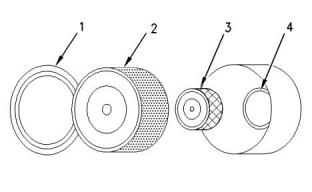
Illustration 34
g00736431
(1) Cover
(2) Primary air cleaner element
(3) Secondary air cleaner element
(4) Air inlet
Cleaning the air filter element will not extend the life
of the air filter element.
1. Remove the cover. Remove the primary air cleaner
element.
Visually inspect the primary air cleaner element
before cleaning. Inspect air cleaner elements for
damage to the pleats, the seals, the gaskets, and the
outer cover. Discard any damaged air cleaner
element.
2. The secondary air cleaner element should be
removed and discarded for every three cleanings
of the primary air cleaner element.
Two methods may be used in order to clean the
primary air cleaner element:
Note: Refer to “Cleaning the Primary Air Cleaner
Elements”.
• pressurized air
3. Cover the air inlet with tape in order to keep out
dirt.
• Vacuum cleaning
4. Clean the inside of the air cleaner cover and body
with a clean, dry cloth.
Pressurized Air
5. Remove the tape from the air inlet. Install the
secondary air cleaner element. Install a primary air
cleaner element that is new or cleaned.
Personal injury can result from air pressure.
Personal injury can result without following prop-
er procedure. When using pressure air, wear a
protective face shield and protective clothing.
6. Install the air cleaner cover.
7. Reset the air cleaner service indicator.
Maximum air pressure at the nozzle must be less
than 205 kPa (30 psi) for cleaning purposes.
This document is printed from SPI². Not for RESALE
![]()
![]()
![]()
![]()
![]()
![]()
![]()
66
SEBU9064
Maintenance Recommendations
Engine Air Cleaner Element (Single Element) - Inspect/Clean/Replace
Pressurized air can be used to clean primary air
cleaner elements that have not been cleaned more
than three times. Use filtered, dry air with a maximum
pressure of 207 kPa (30 psi). Pressurized air will not
remove deposits of carbon and oil.
Inspecting the Primary Air Cleaner
Elements
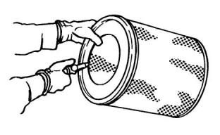
Illustration 36
g00281693
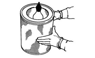
Illustration 35
g00281692
Inspect the clean, dry primary air cleaner element.
Use a 60 W blue light in a dark room or in a similar
facility. Place the blue light in the primary air cleaner
element. Rotate the primary air cleaner element.
Inspect the primary air cleaner element for tears and/
or holes. Inspect the primary air cleaner element for
light that may show through the filter material. If it is
necessary in order to confirm the result, compare the
primary air cleaner element to a new primary air
cleaner element that has the same part number.
Note: When the primary air cleaner elements are
cleaned, always begin with the clean side (inside) in
order to force dirt particles toward the dirty side
(outside).
Aim the air hose so that air flows along the length of
the filter. Follow the direction of the paper pleats in
order to prevent damage to the pleats. Do not aim the
air directly at the face of the paper pleats.
Do not use a primary air cleaner element that has any
tears and/or holes in the filter material. Do not use a
primary air cleaner element with damaged pleats,
gaskets, or seals. Discard damaged primary air
cleaner elements.
Note: Refer to “Inspecting the Primary Air Cleaner
Elements”.
Vacuum Cleaning
Vacuum cleaning is a good method for removing
accumulated dirt from the dirty side (outside) of a
primary air cleaner element. Vacuum cleaning is
especially useful for cleaning primary air cleaner
elements which require daily cleaning because of a
dry, dusty environment.
i04150591
Engine Air Cleaner Element
(Single Element) - Inspect/
Clean/Replace
Cleaning from the clean side (inside) with pressurized
air is recommended prior to vacuum cleaning the dirty
side (outside) of a primary air cleaner element.
Refer to Operation and Maintenance Manual, “Engine
Air Cleaner Service Indicator-Inspect”.
Note: Refer to “Inspecting the Primary Air Cleaner
Elements”.
NOTICE
Never run the engine without an air cleaner element
installed. Never run the engine with a damaged air
cleaner element. Do not use air cleaner elements with
damaged pleats, gaskets or seals. Dirt entering the
engine causes premature wear and damage to en-
gine components. Air cleaner elements help to pre-
vent airborne debris from entering the air inlet.
This document is printed from SPI². Not for RESALE
![]()
![]()
![]()
![]()
![]()
![]()
![]()
SEBU9064
67
Maintenance Recommendations
Engine Air Cleaner Service Indicator - Inspect
• Check for ease of resetting. The service indicator
should reset in less than three pushes.
NOTICE
Never service the air cleaner element with the engine
running since this will allow dirt to enter the engine.
• Check the movement of the yellow core when the
engine is accelerated to the engine rated speed.
The yellow core should latch at the greatest
vacuum that is attained.
A wide variety of air cleaners may be installed for use
with this engine. Consult the OEM information for the
correct procedure to replace the air cleaner.
If the service indicator does not reset easily, or if the
yellow core does not latch at the greatest vacuum,
the service indicator should be replaced. If the new
service indicator will not reset, the hole for the service
indicator may be restricted.
i02335405
Engine Air Cleaner Service
Indicator - Inspect
The service indicator may need to be replaced
frequently in environments that are severely dusty.
Some engines may be equipped with a different
service indicator.
i02927289
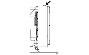
Engine Air Precleaner - Check/
Clean
Some engines are equipped with a differential gauge
for inlet air pressure. The differential gauge for inlet
air pressure displays the difference in the pressure
that is measured before the air cleaner element and
the pressure that is measured after the air cleaner
element. As the air cleaner element becomes dirty,
the pressure differential rises. If your engine is
equipped with a different type of service indicator,
follow the OEM recommendations in order to service
the air cleaner service indicator.
The service indicator may be mounted on the air
cleaner element or in a remote location.
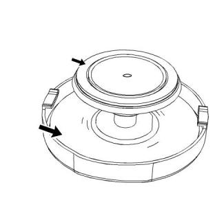
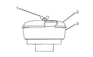
Illustration 38
g01453058
Typical engine air precleaner
(1) Wing nut
(2) Cover
(3) Body
Remove wing nut (1) and cover (2). Check for an
accumulation of dirt and debris in body (3). Clean the
body, if necessary.
Illustration 37
g00103777
Typical service indicator
After cleaning the precleaner, install cover (2) and
wing nut (1).
Observe the service indicator. The air cleaner
element should be cleaned or the air cleaner element
should be replaced when one of the following
conditions occur:
Note: When the engine is operated in dusty
applications, more frequent cleaning is required.
• The yellow diaphragm enters the red zone.
• The red piston locks in the visible position.
Test the Service Indicator
Service indicators are important instruments.
This document is printed from SPI². Not for RESALE
![]()
![]()
![]()

![]()
![]()
![]()
![]()
68
SEBU9064
Maintenance Recommendations
Engine Crankcase Breather - Replace
i05335963
NOTICE
Engine Crankcase Breather -
Replace
Make sure that the components of the breather as-
sembly are installed correctly. Engine damage may
occur if the breather assembly is not working
correctly.
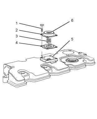
4. Install a new diaphragm and plate (4) for the
breather assembly into the cavity (5) of the valve
mechanism cover.
NOTICE
Keep all parts clean from contaminants.
Contaminants may cause rapid wear and shortened
component life.
5. Install a new spring (3).
6. Install the breather cover (2) and the four screws
(1). Tighten the screws.
i02323089
Engine Mounts - Inspect
Note: The engine mounts may not have been
supplied by Perkins . Refer to the OEM information
for further information on the engine mounts and the
correct bolt torque.
Inspect the engine mounts for deterioration and for
correct bolt torque. Engine vibration can be caused
by the following conditions:
• Incorrect mounting of the engine
• Deterioration of the engine mounts
• Loose engine mounts
Any engine mount that shows deterioration should be
replaced. Refer to the OEM information for the
recommended torques.
i05164949
Engine Oil Level - Check
Illustration 39
g03380583
Typical example
(1) Screws for the breather cover
(2) Breather cover
(3) Spring
(4) Diaphragm and plate
(5) Cavity
(6) Vent hole
Hot oil and hot components can cause personal
injury. Do not allow hot oil or hot components to
contact the skin.
1. Loosen the screws (1) and remove the breather
cover (2) from the valve mechanism cover.
2. Remove the spring (3). Remove the diaphragm
and plate (4).
3. Clean the vent hole (6) and the cavity (5) in the
valve mechanism cover.
This document is printed from SPI². Not for RESALE
![]()
![]()
![]()
![]()
![]()
![]()
![]()
![]()
![]()
SEBU9064
69
Maintenance Recommendations
Engine Oil and Filter - Change
i05336039
Engine Oil and Filter - Change
Hot oil and hot components can cause personal
injury. Do not allow hot oil or hot components to
contact the skin.
NOTICE
Care must be taken to ensure that fluids are con-
tained during performance of inspection, mainte-
nance, testing, adjusting and repair of the product. Be
prepared to collect the fluid with suitable containers
before opening any compartment or disassembling
any component containing fluids.
Dispose of all fluids according to local regulations and
mandates.
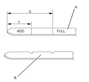
Illustration 40
g03317856
(Y) “ADD” mark. (X) “FULL” mark.
(A) Original oil level gauge
(B) Alternative oil level gauge
NOTICE
Keep all parts clean from contaminants.
NOTICE
Perform this maintenance with the engine stopped.
Contaminants may cause rapid wear and shortened
component life.
Do not drain the oil when the engine is cold. As the oil
cools, suspended waste particles settle on the bottom
of the oil pan. The waste particles are not removed
with the draining cold oil. Drain the crankcase with the
engine stopped. Drain the crankcase with the oil
warm. This draining method allows the waste
particles that are suspended in the oil to be drained
correctly.
Note: Oil gauge (A) or oil gauge (B) may be installed
in the engine.
1. Maintain the oil level between “ADD” mark (Y) and
“FULL” mark (X) on oil level gauge (1). Do not fill
the crankcase above “FULL” mark (X).
NOTICE
Failure to follow this recommended procedure will
cause the waste particles to be recirculated through
the engine lubrication system with the new oil.
Operating your engine when the oil level is above the
“FULL” mark could cause your crankshaft to dip into
the oil. The air bubbles created from the crankshaft
dipping into the oil reduces the oil's lubricating char-
acteristics and could result in the loss of power.
Drain the Engine Oil
After the engine has been run at the normal operating
temperature, stop the engine. Use one of the
following methods to drain the engine crankcase oil:
2. Remove the oil filler cap and add oil, if necessary.
Clean the oil filler cap. Install the oil filler cap.
• If the engine is equipped with a drain valve, turn
the drain valve knob counterclockwise in order to
drain the oil. After the oil has drained, turn the
drain valve knob clockwise in order to close the
drain valve.
• If the engine is not equipped with a drain valve,
remove the oil drain plug in order to allow the oil to
drain. After the oil has drained, the oil drain plug
should be cleaned and installed.
This document is printed from SPI². Not for RESALE
![]()
![]()
![]()
![]()
![]()
![]()
![]()
![]()
![]()
![]()

![]()
![]()
![]()
70
SEBU9064
Maintenance Recommendations
Engine Oil and Filter - Change
Replace the Oil Filter
NOTICE
Perkins oil filters are built to Perkins specifications.
Use of an oil filter not recommended by Perkins
could result in severe engine damage to the engine
bearings, crankshaft, etc., as a result of the larger
waste particles from unfiltered oil entering the engine
lubricating system. Only use oil filters recommended
by Perkins .
1. Remove the oil filter with a suitable tool.
Note: The following actions can be carried out as part
of the preventive maintenance program.
2. Cut the oil filter open with a suitable tool. Break
apart the pleats and inspect the oil filter for metal
debris. An excessive amount of metal debris in the
oil filter may indicate early wear or a pending
failure.
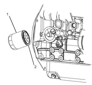
Illustration 41
g03380736
Use a magnet to differentiate between the ferrous
metals and the nonferrous metals that are found in
the oil filter element. Ferrous metals may indicate
wear on the steel and cast iron parts of the engine.
Typical example
3. Clean the sealing surface of the cylinder block.
4. Apply clean engine oil to the new O ring seal (2).
Nonferrous metals may indicate wear on the
aluminum parts, brass parts, or bronze parts of the
engine. Parts that may be affected include the
following items: main bearings, rod bearings,
turbocharger bearings and cylinder heads.
NOTICE
Do not fill the oil filters with oil before installing them.
This oil would not be filtered and could be contami-
nated. Contaminated oil can cause accelerated wear
to engine components.
Due to normal wear and friction, it is not
uncommon to find small amounts of debris in the
oil filter. Consult your Perkins dealer or your
Perkins distributor in order to arrange for a further
analysis if an excessive amount of debris is found
in the oil filter.
5. Install the new oil filter (1) Spin on the oil filter until
the O ring seal contacts the oil filter base. Rotate
the oil filter ¾ of a full turn.
Fill the Engine Crankcase
1. Remove the oil filler cap. Refer to the Operation
and Maintenance Manual for more information on
lubricant specifications. Fill the crankcase with the
correct amount of oil. Refer to the Operation and
Maintenance Manual for more information on refill
capacities.
NOTICE
If equipped with an auxiliary oil filter system or a re-
mote oil filter system, follow the OEM or filter manu-
facturer's recommendations. Under filling or overfilling
the crankcase with oil can cause engine damage.
This document is printed from SPI². Not for RESALE
![]()
![]()
![]()
![]()
![]()
![]()
![]()
![]()
![]()
SEBU9064
71
Maintenance Recommendations
Engine Valve Lash - Check
NOTICE
NOTICE
To prevent crankshaft bearing damage, crank the en-
gine with the fuel OFF. This will fill the oil filters before
starting the engine. Do not crank the engine for more
than 30 seconds.
Only qualified service personnel should perform this
maintenance. Refer to the Service Manual or your au-
thorized Perkins dealer or your Perkins
distributor
for the complete valve lash adjustment procedure.
Operation of Perkins engines with incorrect valve
lash can reduce engine efficiency, and also reduce
engine component life.
2. Start the engine and run the engine at “LOW IDLE”
for 2 minutes. Perform this procedure in order to
ensure that the lubrication system has oil and that
the oil filters are filled. Inspect the oil filter for oil
leaks.
3. Stop the engine and allow the oil to drain back to
the sump for a minimum of 10 minutes.
Ensure that the engine can not be started while
this maintenance is being performed. To help pre-
vent possible injury, do not use the starting motor
to turn the flywheel.
Hot engine components can cause burns. Allow
additional time for the engine to cool before meas-
uring/adjusting valve lash clearance.
Ensure that the engine is stopped before measuring
the valve lash. The engine valve lash can be
inspected and adjusted when the temperature of the
engine is hot or cold.
Refer to Systems Operation, Testing and Adjusting,
“Engine Valve Lash - Inspect/Adjust” for more
information.
Illustration 42
g03306420
(Y) “ADD” mark. (X) “FULL” mark.
(A) Original oil level gauge
(B) Alternative oil level gauge
4. Remove the oil level gauge in order to check the oil
level. Maintain the oil level between the “ADD”
and “FULL” marks on the oil level gauge.
i05153520
Engine Valve Lash - Check
This maintenance is recommended by Perkins as
part of a lubrication and preventive maintenance
schedule in order to help provide maximum engine
life. The maintenance for the valve lash is important in
order to keep the engine compliant.
This document is printed from SPI². Not for RESALE
![]()
![]()
![]()
![]()
![]()
![]()
![]()
![]()
![]()
72
SEBU9064
Maintenance Recommendations
Fan Clearance - Check
i05153591
i05161054
Fan Clearance - Check
Fuel Filter (In-Line)- Replace
Fuel leaked or spilled onto hot surfaces or electri-
cal components can cause a fire. To help prevent
possible injury, turn the start switch off when
changing fuel filters or water separator elements.
Clean up fuel spills immediately.
Note: Refer to Systems Operation, Testing, and
Adjusting, “Cleanliness of Fuel System
Components” for detailed information on the
standards of cleanliness that must be observed
during ALL work on the fuel system.
NOTICE
Ensure that the engine is stopped before any servic-
ing or repair is performed.
The location of the in-line fuel filter will depend on the
application that the engine has been installed.
Illustration 43
g03309719
Typical example
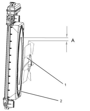
Ensure that the engine is stopped. Ensure that the
battery disconnect switch is in the OFF position.
Ensure that the cooling system is full.
The clearance between the cover (2) and the fan (1)
will require checking. The gap between the edge of
the cover and the tip of the fan blade (A) must be
checked in four equally spaced positions.
• (A) equals 5 mm (0.19685 inch) for the three
cylinder engine and the four cylinder naturally
aspirated engine.
• (A) equals 10 mm (0.39370 inch) for the
turbocharged engine.
Illustration 44
g03315616
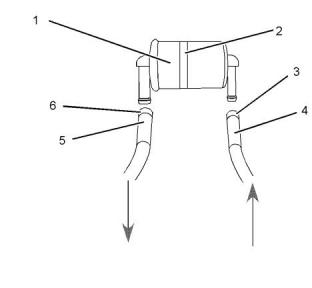
Arrows show fuel flow
Note: The cover is not adjustable.
Note: The in-line fuel filter is an off engine part.
1. Turn the fuel supply valve (if equipped) to the OFF
position. Remove clamp (3) and remove clamp (6).
2. Remove inlet hose (4) and remove outlet hose (5)
from in-line filter (1).
This document is printed from SPI². Not for RESALE
![]()
![]()
![]()
![]()
![]()
![]()
![]()
![]()
![]()
SEBU9064
73
Maintenance Recommendations
Fuel Injector - Test/Change
3. If installed, remove clamp (2) and remove in-line
filter (1) from application.
• The engine will not start or the engine is difficult to
start.
• Not enough power
4. Install new in-line filter (1) and install clamp (2).
• The engine misfires or the engine runs erratically.
• High fuel consumption
5. Install inlet hose (4) and install clamp (3). Install
outlet hose (5) and install clamp (6).
6. Turn the fuel supply valve (if equipped) to the ON
position. Prime the system, refer to this Operation
and Maintenance Manual, “Fuel System - Prime”.
• Black exhaust smoke
• The engine knocks or there is vibration in the
engine.
i02154268
• Excessive engine temperature
Fuel Injector - Test/Change
For further information on the removal and the
installation of the fuel injectors, refer to the
Disassembly and Assembly manual.
For further information on the testing of fuel injectors,
refer to the Testing and Adjusting manual.
Identificationof a suspect Fuel
Injector
Fuel leaked or spilled onto hot surfaces or electri-
cal components can cause a fire.
Work carefully around an engine that is running.
Engine parts that are hot, or parts that are mov-
ing, can cause personal injury.
Make sure that you wear eye protection at all
times during testing. When fuel injection nozzles
are tested, test fluids travel through the orifices of
the nozzle tip with high pressure. Under this
amount of pressure, the test fluid can pierce the
skin and cause serious injury to the operator. Al-
ways keep the tip of the fuel injection nozzle
pointed away from the operator and into the fuel
collector and extension.
NOTICE
If your skin comes into contact with high pressure
fuel, obtain medical assistence immediately.
NOTICE
If a fuel injector is suspected of operating outside of
normal parameters it should be removed by a quali-
fied technician. The suspect fuel injector should be
taken to an authorised agent for inspection.
NOTICE
Do not allow dirt to enter the fuel system. Thoroughly
clean the area around a fuel system component that
will be disconnected. Fit a suitable cover over discon-
nected fuel system component.
Operate the engine at a fast idle speed in order to
identify the faulty fuel injector. Individually loosen and
tighten the union nut for the high pressure pipe to
each fuel injector. Do not loosen the union nut more
than half a turn. There will be little effect on the
engine speed when the union nut to the faulty fuel
injector is loosened.
Regular maintenance of the fuel injectors is
recommended by Perkins . The fuel injectors must be
removed and tested by an authorized agent. The fuel
injectors should not be cleaned as cleaning with
incorrect tools can damage the nozzle. The fuel
injectors should be renewed only if a fault with the
fuel injectors occurs. Some of the problems that may
indicate that new fuel injectors are needed are listed
below:
Consult your authorized Perkins dealer or your
Perkins distributor for further assistance.
This document is printed from SPI². Not for RESALE
![]()
![]()
![]()
![]()
![]()
![]()
![]()
![]()
![]()
![]()
![]()
![]()
![]()
74
SEBU9064
Maintenance Recommendations
Fuel System - Prime
i04145953
Fuel System - Prime
Turn the keyswitch to the ON position for 2 minutes in
order to prime the fuel system. Turn keyswitch to OFF
position, then turn on again. The engine is primed
and ready to start.
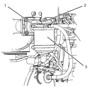
i05337705
Fuel System Primary Filter -
Replace
Fuel leaked or spilled onto hot surfaces or electri-
cal components can cause a fire. To help prevent
possible injury, turn the start switch off when
changing fuel filters or water separator elements.
Clean up fuel spills immediately.
NOTICE
Ensure that the engine is stopped before any servic-
ing or repair is performed.
Remove the Element
1. Turn the fuel supply valve (if equipped) to the OFF
position before performing this maintenance.
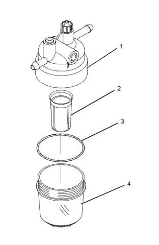
Illustration 45
g03381282
Typical example
2. Place a suitable container under the water
separator in order to catch any fuel that might spill.
Clean up any spilled fuel. Clean the outside body
of the filter assembly.
3. Remove the filter bowl (4) from the fuel filter base
(1).
4. Remove the O-ring seal (3). Discard the O-ring
seal.
5. Remove the filter element (2) from the fuel filter
base (1). Discard the filter element (2).
6. Clean the filter bowl (4).
Install the Element
This document is printed from SPI². Not for RESALE
![]()
![]()
![]()
![]()
![]()
![]()
![]()
SEBU9064
75
Maintenance Recommendations
Fuel System Primary Filter/Water Separator - Drain
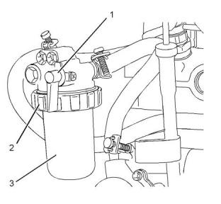
i02627223
Fuel System Primary Filter/
Water Separator - Drain
Fuel leaked or spilled onto hot surfaces or electri-
cal components can cause a fire. To help prevent
possible injury, turn the start switch off when
changing fuel filters or water separator elements.
Clean up fuel spills immediately.
NOTICE
The water separator is not a filter. The water separa-
tor separates water from the fuel. The engine should
never be allowed to run with the water separator more
than half full. Engine damage may result.
Illustration 46
g03381282
Typical example
1. Install a new filter element (2) to the fuel filter base
(1).
2. Lubricate the O ring seal (3) with clean engine oil.
Do NOT fill the bowl with fuel before the assembly
is installed.
3. Install the filter bowl (4) to the fuel filter base (1).
Illustration 47
g01316965
Tighten the filter bowl (4) by hand.
Typical example
4. The secondary fuel filter must be replaced at the
same time as the primary fuel filter. Refer to the
Operation and Maintenance Manual, “Fuel System
Secondary Filter - Replace”.
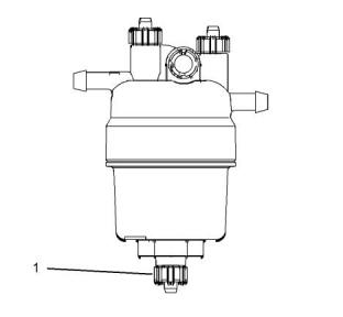
1. Open drain (1). Catch the draining fluid in a
suitable container. Dispose of the drained fluid
correctly.
2. Close drain (1).
NOTICE
The water separator is under suction during normal
engine operation. Ensure that the drain valve is tight-
ened securely to help prevent air from entering the
fuel system.
This document is printed from SPI². Not for RESALE
![]()
![]()
![]()
![]()
![]()
![]()

![]()
![]()
![]()
![]()
![]()
76
SEBU9064
Maintenance Recommendations
Fuel System Secondary Filter - Replace
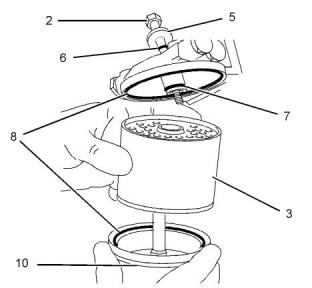
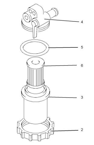
i05337334
Fuel System Secondary Filter -
Replace
Fuel leaked or spilled onto hot surfaces or electri-
cal components can cause a fire. To help prevent
possible injury, turn the start switch off when
changing fuel filters or water separator elements.
Clean up fuel spills immediately.
NOTICE
Do not allow dirt to enter the fuel system. Thoroughly
clean the area around a fuel system component that
will be disconnected. Fit a suitable cover over discon-
nected fuel system component.
Illustration 48
g03317866
Typical example
NOTICE
Care must be taken to ensure that fluids are con-
tained during performance of inspection, mainte-
nance, testing, adjusting and repair of the product. Be
prepared to collect the fluid with suitable containers
before opening any compartment or disassembling
any component containing fluids.
2. Clean the outside of the fuel filter assembly (1).
3. Remove setscrew (2).
4. Remove the canister (3). Ensure that any fluid is
drained into a suitable container.
Dispose of all fluids according to local regulations and
mandates.
Note: The primary filter element must be replaced at
the same time as the secondary filter element. Refer
to Operation and Maintenance Manual, “Fuel System
Primary Filter (Water Separator) Element - Replace”.
Fuel Filter with Canister
1. Close the fuel supply valve.
Illustration 49
g02710378
Typical example
5. Assemble the following items: seals (8), seal (7),
canister (3) and bowl (10). Place washer (5) and
seal (6) on setscrew (2).
This document is printed from SPI². Not for RESALE
![]()
![]()
![]()
![]()
![]()
![]()
![]()
![]()
![]()
![]()
![]()
SEBU9064
77
Maintenance Recommendations
Fuel System Secondary Filter - Replace
6. Fasten the assembly to the fuel filter base with
setscrew (2).
The fuel system will need to be primed after the new
filter is installed. Refer to this Operation and
Maintenance Manual, “Fuel System - Prime”.
Fuel Filter with Element
1. Close the fuel supply valve (1).
Illustration 50
g01334893
Typical example
Illustration 51
g01334895
2. Clean the outside of the fuel filter assembly.
3. Loosen the locking ring (2).
Typical example
Note: Do not fill the fuel filter with fuel. The fuel will
not be filtered and the fuel could be contaminated.
Contaminated fuel can damage your fuel system.
5. Assemble the following items: seal (5), filter
element (6) and casing (3).
4. Remove the casing (3) for the filter and the
element. Ensure that any fluid is drained into a
suitable container.
6. Install the assembled items to the filter base (4).
7. Install the locking ring (2) to the filter head. Rotate
the locking ring in order to lock the assembly.
The fuel system will need to be primed after the new
filter is installed. Refer to Operation and Maintenance
Manual, “Fuel System - Prime”.
This document is printed from SPI². Not for RESALE
![]()
![]()
![]()
![]()
![]()
78
SEBU9064
Maintenance Recommendations
Fuel Tank Water and Sediment - Drain
i02335436
Fuel Storage Tanks
Fuel Tank Water and Sediment
- Drain
Drain the water and the sediment from the fuel
storage tank at the following intervals:
• Weekly
• Service intervals
• Refill of the tank
NOTICE
Care must be taken to ensure that fluids are con-
tained during performance of inspection, mainte-
nance, testing, adjusting and repair of the product. Be
prepared to collect the fluid with suitable containers
before opening any compartment or disassembling
any component containing fluids.
This will help prevent water or sediment from being
pumped from the storage tank into the engine fuel
tank.
If a bulk storage tank has been refilled or moved
recently, allow adequate time for the sediment to
settle before filling the engine fuel tank. Internal
baffles in the bulk storage tank will also help trap
sediment. Filtering fuel that is pumped from the
storage tank helps to ensure the quality of the fuel.
When possible, water separators should be used.
Dispose of all fluids according to local regulations and
mandates.
Fuel Tank
Fuel quality is critical to the performance and to the
service life of the engine. Water in the fuel can cause
excessive wear to the fuel system.
i02813964
Hoses and Clamps - Inspect/
Replace
Water can be introduced into the fuel tank when the
fuel tank is being filled.
Condensation occurs during the heating and cooling
of fuel. The condensation occurs as the fuel passes
through the fuel system and the fuel returns to the
fuel tank. This causes water to accumulate in fuel
tanks. Draining the fuel tank regularly and obtaining
fuel from reliable sources can help to eliminate water
in the fuel.
Inspect all hoses for leaks that are caused by the
following conditions:
• Cracking
• Softness
Drain the Water and the Sediment
• Loose clamps
Fuel tanks should contain some provision for draining
water and draining sediment from the bottom of the
fuel tanks.
Replace hoses that are cracked or soft. Tighten any
loose clamps.
NOTICE
Open the drain valve on the bottom of the fuel tank in
order to drain the water and the sediment. Close the
drain valve.
Do not bend or strike high pressure lines. Do not in-
stall bent or damaged lines, tubes or hoses. Repair
any loose or damaged fuel and oil lines, tubes and
hoses. Leaks can cause fires. Inspect all lines, tubes
and hoses carefully. Tighten all connections to the
recommended torque. Do not clip any other item to
the high pressure lines.
Check the fuel daily. Allow five minutes after the fuel
tank has been filled before draining water and
sediment from the fuel tank.
Fill the fuel tank after operating the engine in order to
drive out moist air. This will help prevent
condensation. Do not fill the tank to the top. The fuel
expands as the fuel gets warm. The tank may
overflow.
Check for the following conditions:
• End fittings that are damaged or leaking
• Outer covering that is chafed or cut
Some fuel tanks use supply pipes that allow water
and sediment to settle below the end of the fuel
supply pipe. Some fuel tanks use supply lines that
take fuel directly from the bottom of the tank. If the
engine is equipped with this system, regular
• Exposed wire that is used for reinforcement
• Outer covering that is ballooning locally
• Flexible part of the hose that is kinked or crushed
• Armoring that is embedded in the outer covering
maintenance of the fuel system filter is important.
This document is printed from SPI². Not for RESALE
![]()
![]()
![]()
![]()
![]()
SEBU9064
79
Maintenance Recommendations
Radiator - Clean
A constant torque hose clamp can be used in place of
any standard hose clamp. Ensure that the constant
torque hose clamp is the same size as the standard
clamp.
Note: For the correct coolant, see this Operation and
Maintenance Manual, “Fluid Recommendations”.
8. Refill the cooling system. Refer to the OEM
information for further information on refilling the
cooling system.
Due to extreme temperature changes, the hose will
harden. Hardening of the hoses will cause hose
clamps to loosen. This can result in leaks. A constant
torque hose clamp will help to prevent loose hose
clamps.
9. Clean the cooling system filler cap. Inspect the
cooling system filler cap's seals. Replace the
cooling system filler cap if the seals are damaged.
Install the, cooling system filler cap.
Each installation application can be different. The
differences depend on the following factors:
10. Start the engine. Inspect the cooling system for
leaks.
• Type of hose
• Type of fitting material
i02335774
• Anticipated expansion and contraction of the hose
Radiator - Clean
• Anticipated expansion and contraction of the
fittings
The radiator is not usually supplied by Perkins . The
following text describes a typical cleaning procedure
for the radiator. Refer to the OEM information for
further information on cleaning the radiator.
Replace the Hoses and the Clamps
Refer to the OEM information for further information
on removing and replacing fuel hoses (if equipped).
Note: Adjust the frequency of cleaning according to
The coolant system and the hoses for the coolant
system are not usually supplied by Perkins . The
following text describes a typical method of replacing
coolant hoses. Refer to the OEM information for
further information on the coolant system and the
hoses for the coolant system.
the effects of the operating environment.
Inspect the radiator for these items: Damaged fins,
corrosion, dirt, grease, insects, leaves, oil and other
debris. Clean the radiator, if necessary.
Personal injury can result from air pressure.
Pressurized System: Hot coolant can cause seri-
ous burns. To open the cooling system filler cap,
stop the engine and wait until the cooling system
components are cool. Loosen the cooling system
pressure cap slowly in order to relieve the
pressure.
Personal injury can result without following prop-
er procedure. When using pressure air, wear a
protective face shield and protective clothing.
Maximum air pressure at the nozzle must be less
than 205 kPa (30 psi) for cleaning purposes.
1. Stop the engine. Allow the engine to cool.
Pressurized air is the preferred method for removing
loose debris. Direct the air in the opposite direction to
the fan's air flow. Hold the nozzle approximately 6 mm
(0.25 inch) away from the radiator fins. Slowly move
the air nozzle in a direction that is parallel with the
radiator tube assembly. This will remove debris that is
between the tubes.
2. Loosen the cooling system filler cap slowly in order
to relieve any pressure. Remove the cooling
system filler cap.
Note: Drain the coolant into a suitable, clean
container. The coolant can be reused.
3. Drain the coolant from the cooling system to a level
that is below the hose that is being replaced.
Pressurized water may also be used for cleaning. The
maximum water pressure for cleaning purposes must
be less than 275 kPa (40 psi). Use pressurized water
in order to soften mud. Clean the core from both
sides.
4. Remove the hose clamps.
Use a degreaser and steam for removal of oil and
grease. Clean both sides of the core. Wash the core
with detergent and hot water. Thoroughly rinse the
core with clean water.
5. Disconnect the old hose.
6. Replace the old hose with a new hose.
7. Install the hose clamps with a torque wrench.
This document is printed from SPI². Not for RESALE
![]()
![]()
![]()
![]()
![]()
80
SEBU9064
Maintenance Recommendations
Starting Motor - Inspect
If the radiator is blocked internally, refer to the OEM
Manual for information regarding flushing the cooling
system.
NOTICE
For any type of leak (coolant, lube, or fuel) clean up
the fluid. If leaking is observed, find the source and
correct the leak. If leaking is suspected, check the flu-
id levels more often than recommended until the leak
is found or fixed, or until the suspicion of a leak is
proved to be unwarranted.
After cleaning the radiator, start the engine. Allow the
engine to operate at low idle speed for three to five
minutes. Accelerate the engine to high idle. This will
help in the removal of debris and the drying of the
core. Slowly reduce the engine speed to low idle and
then stop the engine. Use a light bulb behind the core
in order to inspect the core for cleanliness. Repeat
the cleaning, if necessary.
NOTICE
Accumulated grease and/or oil on an engine is a fire
hazard. Remove the accumulated grease and oil. Re-
fer to this Operation and Maintenance Manual, “En-
gine - Clean” for more information.
Inspect the fins for damage. Bent fins may be opened
with a “comb”. Inspect these items for good condition:
Welds, mounting brackets, air lines, connections,
clamps and seals. Make repairs, if necessary.
• Ensure that the cooling system hoses are correctly
clamped and that the cooling system hoses are
tight. Check for leaks. Check the condition of all
pipes.
i02177969
Starting Motor - Inspect
• Inspect the water pump for coolant leaks.
Perkins recommends a scheduled inspection of the
starting motor. If the starting motor fails, the engine
may not start in an emergency situation.
Note: The water pump seal is lubricated by the
coolant in the cooling system. It is normal for a small
amount of leakage to occur as the engine cools down
and the parts contract.
Check the starting motor for correct operation. Check
the electrical connections and clean the electrical
connections. Refer to the Systems Operation, Testing
and Adjusting Manual, “Electric Starting System -
Test” for more information on the checking procedure
and for specifications or consult your Perkins dealer
or your Perkins distributor for assistance.
Excessive coolant leakage may indicate the need to
replace the water pump seal. For the removal of the
water pump and the installation of water pump and/or
seal, refer to the Disassembly and Assembly Manual,
“Water Pump - Remove and Install” for more
information or consult your Perkins dealer or your
Perkins distributor.
i02177973
• Inspect the lubrication system for leaks at the front
crankshaft seal, the rear crankshaft seal, the oil
pan, the oil filters and the rocker cover.
Walk-Around Inspection
• Inspect the fuel system for leaks. Look for loose
fuel line clamps and/or tie-wraps.
Inspect the Engine for Leaks and
for Loose Connections
• Inspect the piping for the air intake system and the
elbows for cracks and for loose clamps. Ensure
that hoses and tubes are not contacting other
hoses, tubes, wiring harnesses, etc.
A walk-around inspection should only take a few
minutes. When the time is taken to perform these
checks, costly repairs and accidents can be avoided.
For maximum engine service life, make a thorough
inspection of the engine compartment before starting
the engine. Look for items such as oil leaks or coolant
leaks, loose bolts, worn belts, loose connections and
trash buildup. Make repairs, as needed:
• Inspect the alternator belts and any accessory
drive belts for cracks, breaks or other damage.
Belts for multiple groove pulleys must be replaced as
matched sets. If only one belt is replaced, the belt will
carry more load than the belts that are not replaced.
The older belts are stretched. The additional load on
the new belt could cause the belt to break.
• The guards must be in the correct place. Repair
damaged guards or replace missing guards.
• Wipe all caps and plugs before the engine is
serviced in order to reduce the chance of system
contamination.
This document is printed from SPI². Not for RESALE
![]()
![]()
![]()
![]()
![]()
SEBU9064
81
Maintenance Recommendations
Water Pump - Inspect
• Drain the water and the sediment from the fuel
tank on a daily basis in order to ensure that only
clean fuel enters the fuel system.
• Inspect the wiring and the wiring harnesses for
loose connections and for worn wires or frayed
wires.
• Inspect the ground strap for a good connection
and for good condition.
• Disconnect any battery chargers that are not
protected against the current drain of the starting
motor. Check the condition and the electrolyte
level of the batteries, unless the engine is
equipped with a maintenance free battery.
• Check the condition of the gauges. Replace any
gauges that are cracked. Replace any gauge that
can not be calibrated.
i01907756
Water Pump - Inspect
A failed water pump may cause severe engine
overheating problems that could result in the following
conditions:
• Cracks in the cylinder head
• A piston seizure
• Other potential damage to the engine
Note: The water pump seal is lubricated by the
coolant in the cooling system. It is normal for a small
amount of leakage to occur as the engine cools down
and parts contract.
Visually inspect the water pump for leaks. Renew the
water pump seal or the water pump if there is an
excessive leakage of coolant. Refer to the
Disassembly and Assembly Manual, “Water Pump -
Remove and Install” for the disassembly and
assembly procedure.
This document is printed from SPI². Not for RESALE
![]()
82
SEBU9064
Warranty Section
Emissions Warranty Information
Warranty Section
Warranty Information
i05341027
Emissions Warranty
Information
This engine may be certified to comply with exhaust
emission standards and gaseous emission standards
that are prescribed by the law at the time of
manufacture. This engine may be covered by an
Emissions Warranty.
For a full warranty statement contact your Perkins
dealer or your Perkins distributor. For customers that
have a valid user name and password, for perkins.
com . Login then go to TIPSS, and the warranty
information can be accessed.
This document is printed from SPI². Not for RESALE
![]()
SEBU9064
83
Reference Information Section
Engine Protection Plans
Reference Information
Section
www.perkins.com
NOTICE
Dependant upon engine type and application.
Reference Materials
i04224089
Engine Protection Plans
(Extended Service Contract)
Extended Service Contracts-purchased in minutes,
protected for years.
Extended Service Contracts (ESC) protect you from
the stress that unexpected repair work brings to your
life by covering the cost of getting your engine up and
running again. Unlike other extended warranties,
Perkins Platinum ESC protects you against all
component part failures.
Purchase peace of mind from only £0.03 / $0.05 /
euro 0.04 a day and let an ESC make your dreams a
reality.
Why buy an Extended Service Contract?
1. No surprises - total protection from unexpected
repair cost (parts, labor, and travel).
2. Enjoy longer lasting product support from Perkins
global network.
3. Genuine Perkins parts ensure continued engine
performance.
4. Highly trained technicians carry out all repairs.
5. Transferable coverage should you sell your
machine.
Flexible coverage provides the right level of
protection for your Perkins Engine. Coverage can be
extended to 2 years/ 1,000 hours right up to 10 year/
40,000
You can buy an ESC at any time during standard
warranty - even the last day!
Each Perkins Distributor has highly trained and
experienced Perkins Product Support Service
Technicians. The Support Service are equipped, and
available around the clock to get your engine running
again with the minimum of downtime. Buying an ESC
means that you get all this for free.
To purchase an Extended Service Contract, is quick
and simple! Contact your local Perkins Distributor
now and the distributor can provide you with a quote
in minutes. You can locate your nearest Perkins
Distributor by visiting:
This document is printed from SPI². Not for RESALE
![]()
![]()
![]()
84
SEBU9064
Index Section
Index
A
D
After Starting Engine........................................ 30
After Stopping Engine...................................... 36
Alternator - Inspect .......................................... 54
Alternator and Fan Belts - Inspect/Adjust........ 55
Adjustment................................................... 55
Inspection..................................................... 55
Alternator and Fan Belts - Replace.................. 56
Removal and Installation Procedure............ 56
Diagnostic Flash Code Retrieval..................... 26
Diagnostic Lamp.............................................. 26
Driven Equipment - Check............................... 63
E
Electrical System..............................................11
Grounding Practices .....................................11
Emergency Stopping....................................... 36
Emissions Certification Film ............................ 18
Emissions Warranty Information...................... 82
Engine - Clean................................................. 64
Engine Air Cleaner Element (Dual Element)
- Inspect/Clean/Replace ................................ 64
Cleaning the Primary Air Cleaner Elements
................................................................... 65
Servicing the Air Cleaner Elements............. 64
Engine Air Cleaner Element (Single
B
Battery - Replace............................................. 57
Battery Electrolyte Level - Check .................... 57
Before Starting Engine ...............................10, 29
Burn Prevention................................................. 7
Batteries......................................................... 8
Coolant........................................................... 7
Oils................................................................. 8
Element) - Inspect/Clean/Replace................. 66
Engine Air Cleaner Service Indicator -
C
Inspect........................................................... 67
Test the Service Indicator............................. 67
Engine Air Precleaner - Check/Clean.............. 67
Engine Crankcase Breather - Replace............ 68
Engine Diagnostics.......................................... 26
Engine Mounts - Inspect.................................. 68
Engine Oil and Filter - Change ........................ 69
Drain the Engine Oil..................................... 69
Fill the Engine Crankcase............................ 70
Replace the Oil Filter.................................... 70
Engine Oil Level - Check................................. 68
Engine Operation............................................. 31
General Engine Operation........................... 31
Engine Protection Plans (Extended Service
Contract)........................................................ 83
Engine Starting...........................................10, 29
Engine Stopping.........................................11, 36
Engine Valve Lash - Check.............................. 71
Cold Weather Operation.................................. 32
Hints for Cold Weather Operation................ 32
Idling the Engine .......................................... 33
Recommendations for Coolant Warm Up .... 33
Recommendations for the Coolant .............. 33
Viscosity of the Engine Lubrication Oil......... 33
Coolant (Commercial Heavy-Duty) - Change.. 58
Drain ............................................................ 58
Fill................................................................. 59
Flush ............................................................ 58
Coolant (ELC) - Change.................................. 59
Drain ............................................................ 60
Fill................................................................. 60
Flush ............................................................ 60
Coolant Level - Check ..................................... 61
Engines With a Coolant Recovery Tank....... 61
Engines Without a Coolant Recovery Tank . 62
Coolant Temperature Regulator - Replace...... 62
Cooling System Supplemental Coolant
F
Additive (SCA) - Test/Add.............................. 63
Add the SCA, If Necessary.......................... 63
Test for SCA Concentration ......................... 63
Crushing Prevention and Cutting Prevention .... 9
Fan Clearance - Check.................................... 72
Features and Controls..................................... 22
Fire Prevention and Explosion Prevention ........ 8
Fire Extinguisher............................................ 9
Lines, Tubes and Hoses ................................ 9
This document is printed from SPI². Not for RESALE
![]()
SEBU9064
85
Index Section
Fluid Recommendations.......................38, 43, 45
Diesel Fuel Characteristics ......................... 47
Diesel Fuel Requirements ........................... 45
ELC Cooling System Maintenance.............. 40
Engine Oil .................................................... 43
General Coolant Information........................ 38
General Information..................................... 45
General Lubricant Information ..................... 43
Foreword............................................................ 4
California Proposition 65 Warning ................. 4
Literature Information..................................... 4
Maintenance.................................................. 4
Maintenance Intervals.................................... 4
Operation....................................................... 4
Overhaul ........................................................ 4
Safety............................................................. 4
Fuel and the Effect from Cold Weather............ 34
Fuel Conservation Practices............................ 31
Fuel Filter (In-Line) - Replace.......................... 72
Fuel Injector - Test/Change.............................. 73
Identification of a suspect Fuel Injector........ 73
Fuel Related Components in Cold Weather.... 35
Fuel Filters ................................................... 35
Fuel Heaters ................................................ 35
Fuel Tanks.................................................... 35
Fuel System - Prime........................................ 74
Fuel System Primary Filter - Replace.............. 74
Install the Element ....................................... 74
Remove the Element ................................... 74
Fuel System Primary Filter/Water Separator
- Drain............................................................ 75
Fuel System Secondary Filter - Replace......... 76
Fuel Filter with Canister ............................... 76
Fuel Filter with Element................................ 77
Fuel Tank Water and Sediment - Drain............ 78
Drain the Water and the Sediment............... 78
Fuel Storage Tanks...................................... 78
Fuel Tank ..................................................... 78
H
Hoses and Clamps - Inspect/Replace............. 78
Replace the Hoses and the Clamps ............ 79
I
Important Safety Information............................. 2
L
Lifting and Storage........................................... 20
M
Maintenance Interval Schedule....................... 54
Commissioning............................................ 54
Daily............................................................. 54
Every 1000 Service Hours........................... 54
Every 12 000 Service Hours or 6 Years....... 54
Every 2000 Service Hours........................... 54
Every 250 Service Hours or 6 Months ......... 54
Every 3000 Service Hours........................... 54
Every 3000 Service Hours or 2 Years.......... 54
Every 50 Service Hours or Weekly .............. 54
Every 500 Service Hours............................. 54
Every 500 Service Hours or 1 Year.............. 54
When Required............................................ 54
Maintenance Recommendations..................... 51
Maintenance Section....................................... 37
Model View Illustrations................................... 12
Components for Electronic Control.............. 15
Fuel System Components............................ 14
The 403F-15 Engine View ........................... 12
Monitoring System........................................... 22
O
Operation Section............................................ 20
Overspeed....................................................... 23
G
Gauges and Indicators .................................... 22
Indicators and Lamps................................... 22
General Hazard Information.............................. 6
Containing Fluid Spillage............................... 7
Fluid Penetration............................................ 7
Pressure Air and Water.................................. 7
General Information......................................... 12
P
Plate Locations and Film Locations................. 18
Product Description......................................... 15
Engine Specifications .................................. 15
Product Identification Information.................... 18
Product InformationSection ............................ 12
Product Lifting.................................................. 20
Product Storage............................................... 20
Condition for Storage................................... 20
This document is printed from SPI². Not for RESALE
![]()
86
SEBU9064
Index Section
R
Radiator - Clean............................................... 79
Reference Information..................................... 18
Record for Reference................................... 18
Reference InformationSection........................ 83
Reference Materials ........................................ 83
Refill Capacities............................................... 37
Cooling System............................................ 37
Lubrication System ...................................... 37
S
Safety Messages............................................... 5
(A) Universal Warning.................................... 5
Safety Section ................................................... 5
Self-Diagnostics............................................... 26
Sensors and Electrical Components............... 23
Severe Service Application.............................. 52
Environmental Factors................................. 52
Incorrect Maintenance Procedures.............. 53
Incorrect Operating Procedures................... 53
Starting Motor - Inspect ................................... 80
Starting the Engine.......................................... 29
Starting with Jump Start Cables ...................... 30
Stopping the Engine ........................................ 36
System Pressure Release............................... 51
Coolant System............................................ 51
Engine Oil .................................................... 51
Fuel System................................................. 51
T
Table of Contents............................................... 3
W
Walk-Around Inspection .................................. 80
Inspect the Engine for Leaks and for Loose
Connections............................................... 80
Warranty Information....................................... 82
Warranty Section............................................. 82
Water Pump - Inspect...................................... 81
Welding on Engines with Electronic Controls.. 51
This document is printed from SPI². Not for RESALE
![]()
Product and Dealer Information
Note: For
product identification plate locations, see the section “Product Identification
Information” in the Operation and Maintenance Manual.
Delivery Date:
Product Information
Model:
Product Identification Number:
Engine Serial Number:
Transmission
Serial Number:
Generator Serial Number:
Attachment Serial Numbers:
Attachment Information:
Customer Equipment Number:
Dealer Equipment
Number:
Dealer Information
Name:
Branch:
Address:
Dealer
Phone
Hours
Contact
Number
Sales:
Parts:
Service:
This document is printed from SPI². Not for RESALE
![]()
![]()
![]()
![]()
![]()
![]()
![]()
![]()
![]()
![]()
![]()
![]()
![]()
![]()
![]()
![]()
![]()
![]()
![]()
![]()
![]()
![]()
![]()
![]()
![]()
©2013 Perkins Engines Company Limited
All Rights Reserved
Printed in U.K.
This document is printed from SPI². Not for RESALE