 English
 Espaol
 Franais
 阿拉伯
阿拉伯 中文
中文 Deutsch
 Italiano
 Português
 日本
日本 韩国
韩国 български
 hrvatski
 esky
esky Dansk
Dansk Nederlands
 suomi
suomi Ελληνικ
 印度
印度 norsk
norsk Polski
 Roman
Roman русский
 Svenska
Perkins珀金斯100维修手册供应商,Perkins珀金斯100维修手册技术价格规格咨询服务,Perkins珀金斯100维修手册零配件供应,Perkins珀金斯100维修手册售后服务中心,Perkins珀金斯100维修手册,Perkins珀金斯100维修手册详细的技术参数,

产品中心
Perkins珀金斯100维修手册二(英文)
详细描述
Special requirements
Torque Nm (lbf ft) kgf m
102-05, 103-07
11 (8) 1,1
6 (4.4) 0,6
15 (11) 1,5
103-10
103-13, 103-15, 104-19, 104-22
Caution: Connections should be blanked off until assembly.
Notes:
For emissions approved engines. If a new fuel injection pump is fitted, shims of the same thickness as the
originals and a pump with the same part number must be fitted.
For emissions approved engines. If the fuel injection pump is put back, it is essential that the fuel
adjustment screw is not altered from the original setting. The maximum No Load Speed should be checked
after assembly.
102
Workshop Manual, TPD 1377E, issue 4
This document has been printed from SPI². Not for Resale
![]()
![]()
![]()
![]()
![]()
![]()

11
100 Series
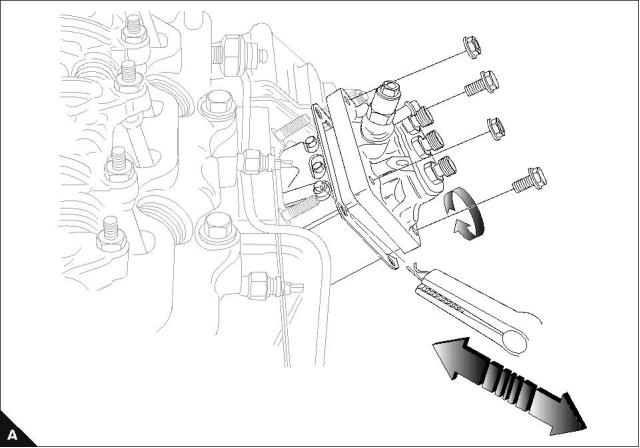
Banjo Bolt
Operation 11-7
The torque setting for the banjo bolt (A1), fitted to the fuel injection pump, for the 103-10 engines (KD) is
20,0 Nm (14.75 lbf ft) 2,04 kgf m. The torque setting for all other engines is 7,0 Nm (5.16 lbf ft) 0,71 kgf m.
1
Workshop Manual, TPD 1377E, issue 4
103
This document has been printed from SPI². Not for Resale
![]()
![]()
![]()
![]()
11
100 Series
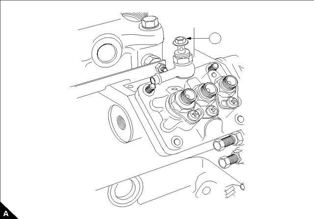
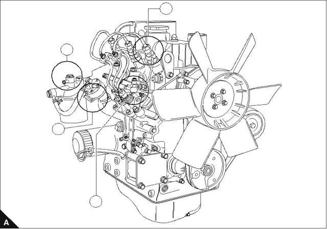
Vent points
To eliminate air from the fuel system
Operation 11-8
To vent the 100 series fuel system
1 Identify the location of fuel lift pump (A3).
2 Locate the vent screw on top of the fuel filter (A2) and loosen off.
3 Operate the hand primer on lift pump until air free fuel flows. Tighten the vent screw.
4 Identify the vent screw on the fuel injection pump (A4) and loosen off. Operate the hand primer until air free
fuel flows. Tighten the vent screw.
5 Identify the fuel pipes from fuel injection pump to the atomiser (A1) and loosen them all off at the atomiser
end. Operate the starter motor until fuel flows from the injector pipes. Tighten all pipe connections.
The engine is now ready to start.
Caution: When the starter motor is operated, do not exceed continuous rotation for more than 15 second
periods. Wait for 30 seconds between periods of turning if fuel does not flow on initial rotation.
1
2
3
4
104
Workshop Manual, TPD 1377E, issue 4
This document has been printed from SPI². Not for Resale
![]()
![]()
![]()
![]()
100 Series
12
Cooling system
12
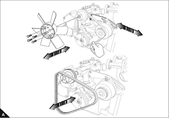
Fan and mounting
To remove and to fit
Operation 12-1
Special requirements
Torque Nm (lbf ft) kgf m
Setscrews
11 (8) 1,1
Depress the fan belt at the centre between the crankshaft pulley and the alternator pulley with a finger force of
49 N (11 lbf) 5 kgf, approximately. The belt deflection is shown in the table below:
Engine type
Belt deflection
4 mm Approx.
5 mm Approx.
6 mm Approx.
7 mm Approx.
102-05, 103-07
103-10
103-13, 103-15, 104-19
104-22
Workshop Manual, TPD 1377E, issue 4
105
This document has been printed from SPI². Not for Resale
![]()
![]()
![]()
![]()
![]()

12
100 Series
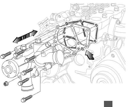
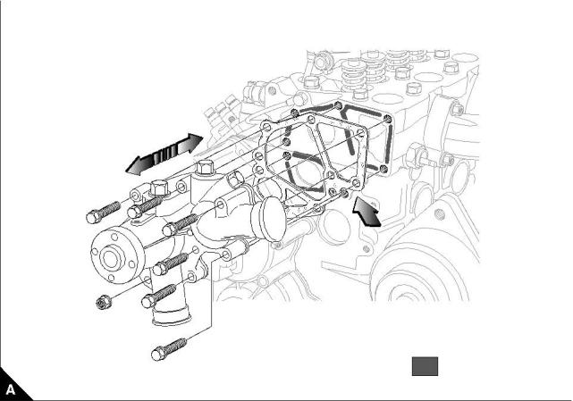
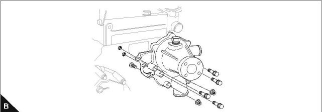
Coolant pump
To remove and to fit
Operation 12-2
Special requirements
POWERPART products
Description
Part number
Silicone RTV sealing and jointing compound
1861108
Notes:
On assembly apply Powerpart silicone RTV sealing and jointing compound to the cylinder block of 102-05,
103-07 and 103-10 engines.
A small amount of leakage of coolant across the surface of the face seal in the coolant pump is normal. Its
purpose is to provide lubrication for the seal. There is a hole in the coolant pump body to allow coolant to
drain. Small amounts of coolant might be seen intermittently from the drain hole during the engine operation
cycle.
Signs of a coolant through the drain hole are not an indication that the pump is faulty. Coolant stains or
intermittent drops of coolant from the hole, indicate normal operation of the pump.
102-05
103-07
103-10
A
POWERPART silicone
gasket sealant
Continued
106
Workshop Manual, TPD 1377E, issue 4
This document has been printed from SPI². Not for Resale
![]()
![]()
![]()
![]()
![]()
![]()
![]()

12
100 Series
103-13
103-15
104-19
104-22
Workshop Manual, TPD 1377E, issue 4
107
This document has been printed from SPI². Not for Resale
![]()
![]()
12
100 Series
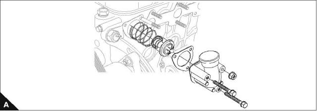
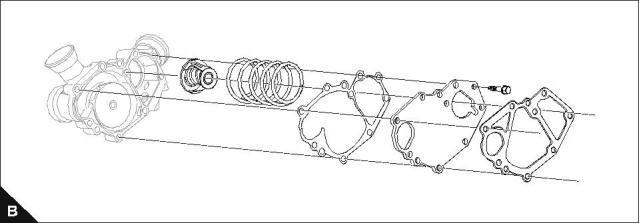
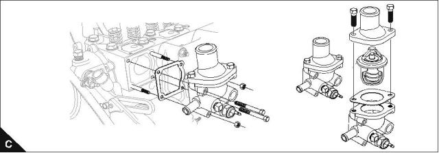
Thermostat
To remove and to fit
Operation 12-3
Note: The vent hole on the thermostat must be fitted in the "12 o'clock" position.
102-05
103-07
103-10
103-13
103-15
104-19
104-22
108
Workshop Manual, TPD 1377E, issue 4
This document has been printed from SPI². Not for Resale
![]()
![]()
![]()
![]()
12
100 Series
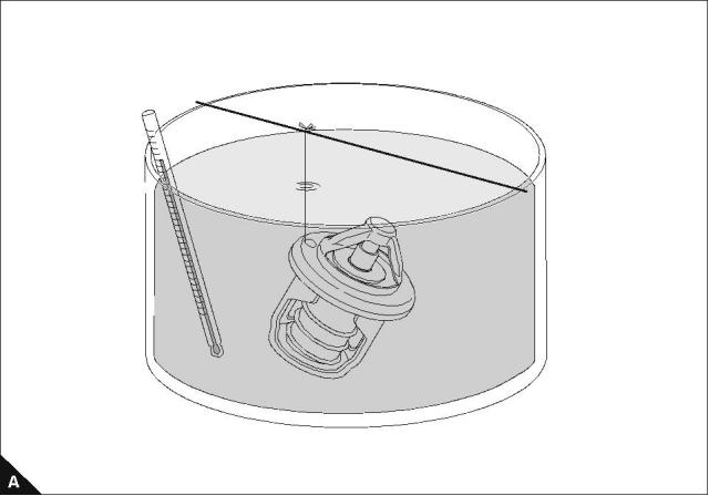
To test and inspect
Operation 12-4
Special requirements
Engine model
Temperature when valve
Temperature when fully
(wax pellet type thermostat)
starts to open °C (°F)
open °C (°F)
73 to 77
(163.4 to 170.6)
87
(188.6)
102-05, 103-07
80 to 84
(176 to 183.2)
95
(203)
103-10, 103-13, 103-15, 104-19, 104-22
Renew the thermostat if the valve is:
Open at ambient temperature.
Closed at the fully open temperature.
1 Place the thermostat into the water.
2 Increase the water temperature gradually and record the water temperature when the valve starts to open
and the temperature when the valve is fully open. The standard values are given in the table.
Notes:
The "Start to open" temperature will be stamped on the thermostat.
3 to 5 minutes will be required before the valve starts to open.
Workshop Manual, TPD 1377E, issue 4
109
This document has been printed from SPI². Not for Resale
![]()
![]()
![]()
![]()
![]()
![]()
![]()
![]()

This page is intentionally blank
This document has been printed from SPI². Not for Resale
100 Series
13
Flywheel and housing
13
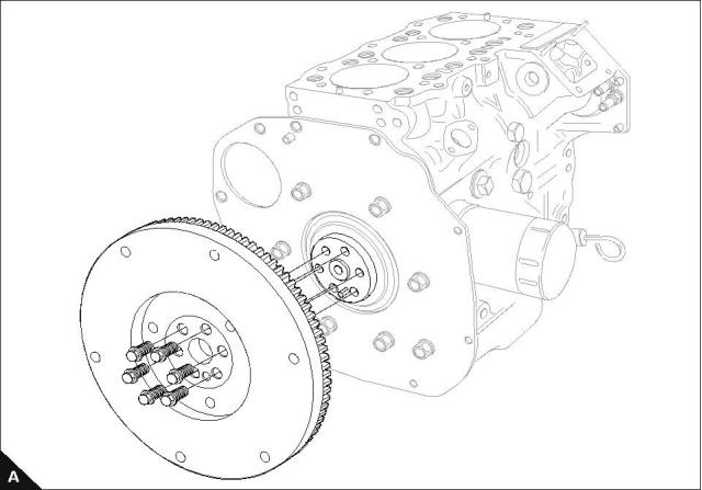
Flywheel
To remove and to fit
Operation 13-1
Special requirements
Torque Nm (lbf ft) kgf m
Flywheel setscrews
73 (54) 7,4
Workshop Manual, TPD 1377E, issue 4
111
This document has been printed from SPI². Not for Resale
![]()
![]()
![]()
![]()
![]()
13
100 Series
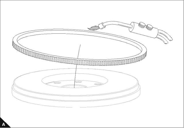
To inspect
Operation 13-2
If the ring gear is excessively damaged or worn, renew.
When wear is not excessive remove ring gear and reinstall 90° from original position. To install, preheat the
ring gear to 120 °C to 150 °C.
Caution: Heat evenly, do not locally overheat.
112
Workshop Manual, TPD 1377E, issue 4
This document has been printed from SPI². Not for Resale
![]()
![]()
![]()
![]()
13
100 Series
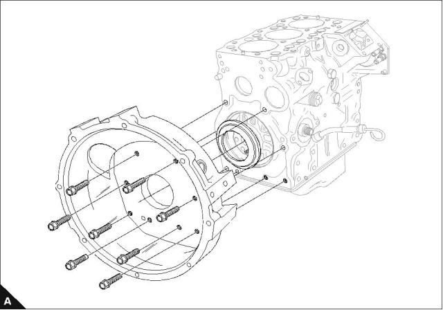
Flywheel housing (if fitted)
To remove and to fit
Operation 13-3
Special requirements
Torque Nm (lbf ft) kgf m
102-05, 103-07
15 (11) 1,5
50 (37) 5,1
25 (18) 2,6
103-10
103-13, 103-15, 104-19, 104-22
Note: Only 104-22 engines have the backplate and housing fitted together.
Workshop Manual, TPD 1377E, issue 4
113
This document has been printed from SPI². Not for Resale
![]()
![]()
![]()
![]()

This page is intentionally blank
This document has been printed from SPI². Not for Resale
100 Series
14
Electrical equipment
14
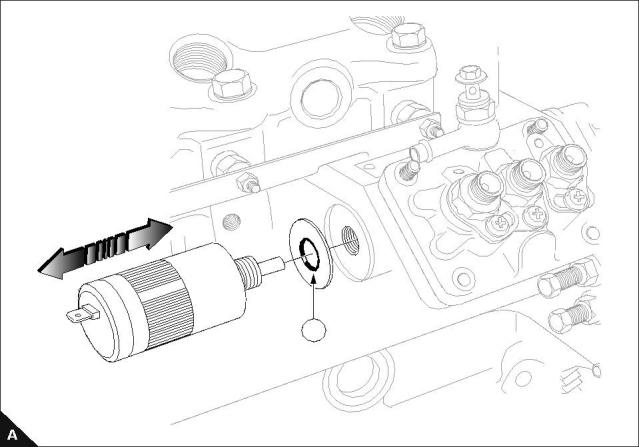
Electrical shut off solenoid (ESOS)
To remove and to fit
Operation 14-1
Special requirements
Torque Nm (lbf ft) kgf m
Solenoid
17 (12) 1,7
Note: Remember the location of special washer (A1).
1
Workshop Manual, TPD 1377E, issue 4
115
This document has been printed from SPI². Not for Resale
![]()
![]()
![]()
![]()
![]()
14
100 Series
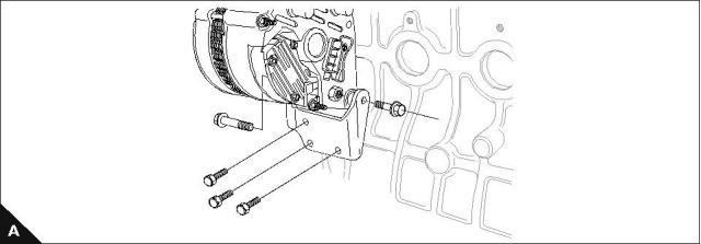
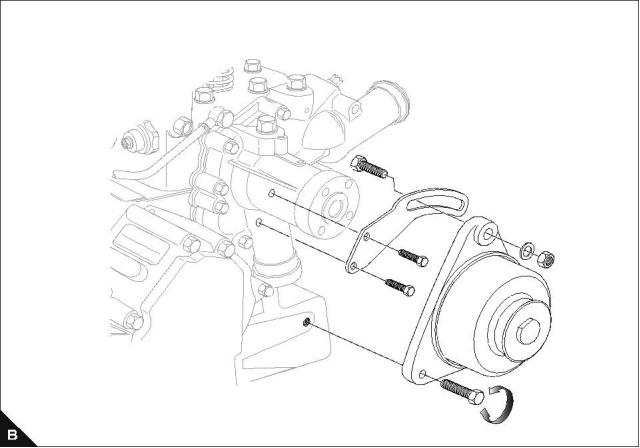
Alternator
To remove and to fit
Operation 14-2
103-13
103-15
104-19
104-22
102-05
103-07
103-10
116
Workshop Manual, TPD 1377E, issue 4
This document has been printed from SPI². Not for Resale
![]()
![]()
![]()
![]()
14
100 Series
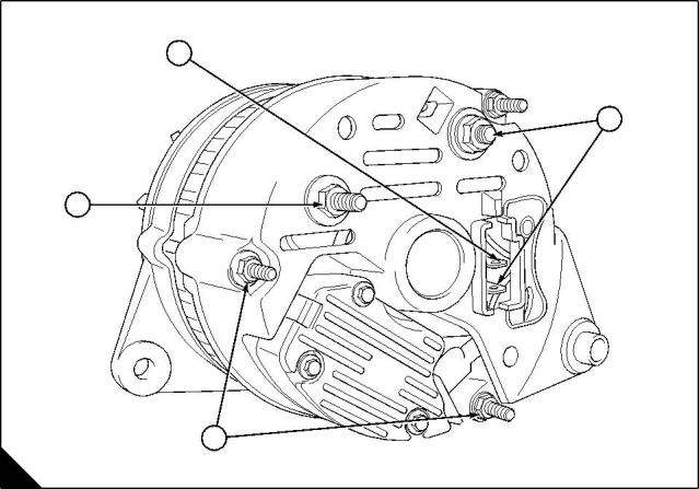
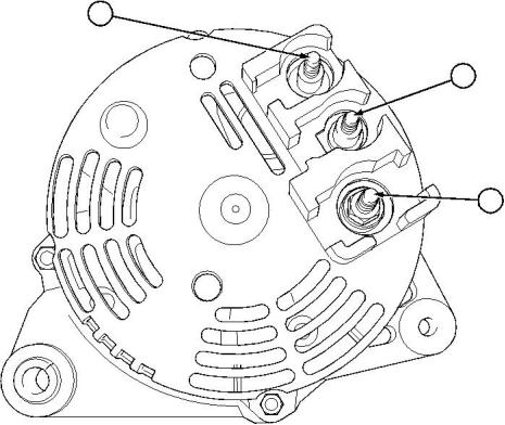
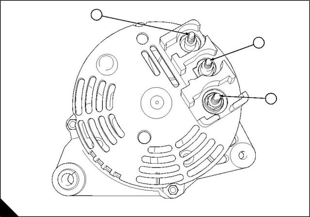
Alternator Testing
Operation 14-3
To avoid the return of parts that are not faulty, follow this procedure for all suspected failures. This will isolate
the problem between either the alternator or the main electrical system.
Check that all connections to the alternator are secure and free from contamination. If the alternator is earthed
using the engine block check that there is a good connection between the alternator, the earth connection and
the engine block. If the alternator mounting bracket is of the black painted type, the bracket should be removed
from the engine block and the paint removed from the mounting surfaces between the alternator, the mounting
bracket and the engine block.
If the machine tachometer is not operating, check the security of the ‘W’ terminal (A3, B3).
If the alternator is excessively contaminated by dust or dirt, use an airline and compressed air applied to the
vent holes on the alternator.
If the ignition warning lamp is illuminated, check the phase wiring (A4, B1).
Check the alternator charging voltage with a volt meter between the alternator +Ve (A1, B2) and the alternator
earth terminal (A2) when the engine is operating at idle, with the minimal electrical load. The voltage should
be between 13.6 and 14.7 volts, if it is outside this range then the alternator is faulty.
Notes:
Graphic A - External fan type.
Graphic B - Internal fan type.
4
1
3
2
A
K1242
Workshop Manual, TPD 1377E, issue 4
117
This document has been printed from SPI². Not for Resale
![]()
![]()
![]()
![]()
![]()
![]()
14
100 Series
3
1
2
B
K1243
118
Workshop Manual, TPD 1377E, issue 4
This document has been printed from SPI². Not for Resale
![]()
![]()
14
100 Series
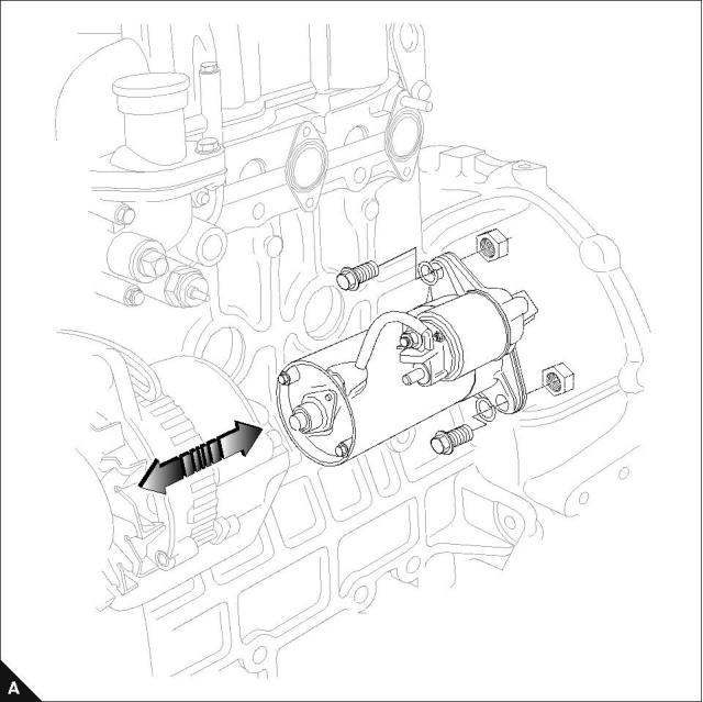
Starter motor
To remove and to fit
Operation 14-4
Workshop Manual, TPD 1377E, issue 4
119
This document has been printed from SPI². Not for Resale
![]()
![]()
![]()
![]()
14
100 Series
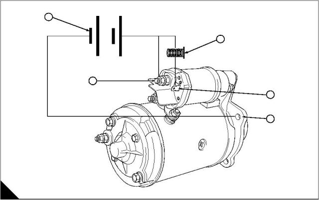
Starter Motor Testing
Operation 14-5
Before removing a suspect faulty starter motor, check the security of all of the electrical connections on the
starter motor.
To test the starter motor use:
12 volt fully charged battery (A5).
Two heavy duty cables with suitable clips.
One small lead with an in-line switch capacity of 5 amperes minimum. The switch (A1) should be of the
push to make type.
Secure the starter motor in a vice.
Connect the leads as shown in the diagram (A2, A3, A4), there should be no operation of the starter motor. If
there is any smoke, buzzing or sparking from the starter motor, it is faulty.
Operate the switch and the solenoid should operate, moving the pinion forward to engage the starter. The
starter motor pinion will then rotate. Releasing the switch will allow the pinion to retract and stop rotating.
If there is any abnormal noise, such as knocking, electrical buzzing, smoke, the starter does not operate, or
the pinion does not move forward or backward, or the pinion does not rotate, the starter motor is faulty.
If the starter motor operates correctly then the machine electrical system is faulty.
A1 - Lead with push button switch.
A2 - Lucar connector for ignition switch.
A3 - Starter earth connection 8.0 - 8.5 Nm
A4 - Solenoid connection 5.6 - 6.2 Nm.
A5 - 12 volt battery.
Note: The starter motor earth (A3) should be connected directly to B- or via another earth. This should not be
used as the main engine earth.
-
+
5
1
4
2
3
A
K1244
120
Workshop Manual, TPD 1377E, issue 4
This document has been printed from SPI². Not for Resale
![]()
![]()
![]()
![]()
![]()
![]()
![]()
![]()
![]()
![]()
![]()
![]()
14
100 Series
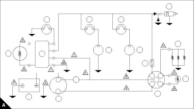
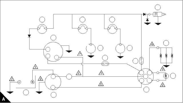
Wiring diagram 14 and 15 amp alternator - 102-05, 103-07, 103-10
Maximum circuit
resistance
Maximum circuit
volt drop
Circuit
Cable number
Circuit current
Remarks
Alternator
charging
14 amp (2 cyl)
15 amp (3 cyl)
0.036 Ù (2 cyl)
0.033 Ù (3 cyl)
See Glow Plugs
Circuit
0.5 Volt
Starter motor
solenoid
See Glow Plugs
Circuit
15.75 amp
0.04 Ù
0.63 Volt
0.5 Volt
(Peak max)
26 amp (2 cyl)
39 amp (3 cyl)
STD glow plugs
(via glow signal)
0.0192 Ù (2 cyl)
0.0128 Ù (3 cyl)
Wiring diagram maximum circuit resistance
The resistance of battery cables 1, 2 and 3 must not exceed 0.0018 Ù.
Note: If a glow signal is not used - it is still necessary to connect terminal 19 and 17 on the switch.
1 Alternator warning lamp
2 Regulator
9 Thermostat switch
10 Fuse
3 Alternator
11 Key switch
4 Battery
12 Glow signal
5 Starter motor
13 Glow plugs
6 Oil pressure warning lamp
7 Oil pressure switch (1)
8 Water temperature warning lamp
14 Solenoid switch
15 A delayed fuse can be fitted if required
(1) Max current draw for standard oil pressure switch is 0.42 amps (5 Watt lamp max).
= Diode. Capacity: Current 3 amp. Reverse Voltage: 600V. (This is mandatory).
14
1
6
8
Sb
Sb
G
Y
R
B
13
7
9
3
2
10
AC
50
17
19
12
15
30
B
S
11
4
5
Workshop Manual, TPD 1377E, issue 4
121
This document has been printed from SPI². Not for Resale
![]()
![]()

![]()
14
100 Series
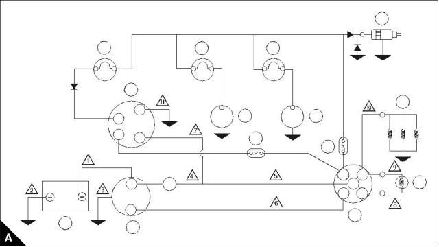
Wiring diagram 40 amp alternator - 103-10 (when fitted with optional alternator)
Maximum circuit
resistance
Maximum circuit
volt drop
Circuit
Cable number
Circuit current
Remarks
Alternator
charging
See Glow Plugs
Circuit
40 amp
0.0125 Ùs
0.04 Ùs
0.5 Volt
0.63 Volt
0.5 Volt
Starter motor
solenoid
See Glow Plug
Circuit
15.75 amp
STD glow plugs
(via glow signal)
(Peak max)
39 amp
0.0128 Ùs
Wiring diagram maximum circuit resistance
The resistance of battery cables 1,2 and 3 must not exceed 0.0018 Ù.
1 Alternator warning lamp
2 Alternator
9 Key switch
10 Glow signal
11 Glow plugs
12 Fuse
3 Battery
4 Starter motor
5 Oil pressure warning lamp
6 Oil pressure switch (1)
7 Water temperature warning lamp
8 Thermostat switch
13 Fuse
14 Solenoid switch
15 A delayed fuse can be fitted if required
(1) Max current draw for standard oil pressure switch is 0.42 amps (5 Watt lamp max).
= Diode. Capacity: Current 3 amp. Reverse Voltage: 600V. (This is mandatory).
14
1
5
7
2
11
6
8
N
F
B
12
13
AC
50
17
19
10
B
15
30
S
9
3
4
122
Workshop Manual, TPD 1377E, issue 4
This document has been printed from SPI². Not for Resale
![]()
![]()

![]()
14
100 Series
Wiring diagram 55 amp alternator - 103-15, 104-19, 104-22
Maximum circuit
resistance
Maximum circuit
volt drop
Circuit
Cable number
Circuit current
Remarks
Alternator
charging
See Glow Plugs
Circuit
55 amp
0.009 Ù
0.04 Ù
0.5 Volt
Starter motor
solenoid
See Glow Plugs
Circuit
15.75 amp
0.63 Volt
0.5 Volt
(Peak max)
39 amp (3 cyl)
52 amp (4 cyl)
STD glow plugs
(via glow signal)
0.0128 Ù (3 cyl)s
0.0096 Ù (4 cyl)s
Wiring diagram maximum circuit resistance
The resistance of battery cables 1, 2 and 3 must not exceed 0.0018 Ù.
2
Note: Maximum cable size for 375 lucar terminals on the alternator is 65/0,3 mm (4,5 mm ) therefore twin
cables are required at the connection to the alternator.
1 Alternator warning lamp
2 Alternator
8 Thermostat switch
9 Key switch
3 Battery
10 Glow signal
4 Starter motor
11 Glow plugs
5 Oil pressure warning lamp
6 Oil pressure switch (1)
7 Water temperature warning lamp
12 Fuse
13 Solenoid switch
14 A delayed fuse can be fitted if desired
(1) Max current draw for standard oil pressure switch is 0.42 amps (5 Watt lamp max).
= Diode. Capacity: Current 3 amp. Reverse Voltage: 600V. (This is mandatory).
14
1
5
7
2
11
B
B
6
8
N
F
12
13
AC
50
17
19
10
B
S
15
30
9
3
4
Workshop Manual, TPD 1377E, issue 4
123
This document has been printed from SPI². Not for Resale
![]()
![]()

![]()
14
100 Series
Wiring diagram 40 amp alternator - 103-13
Maximum circuit
resistance
Maximum circuit
volt drop
Circuit
Cable number
Circuit current
Remarks
Alternator
charging
See Glow Plugs
Circuit
40 amp
0.0125 Ù
0.04 Ù
0.5 Volt
0.63 Volt
0.5 Volt
Starter motor
solenoid
See Glow Plugs
Circuit
15.75 amp
STD glow plugs
(via glow signal)
(Peak max)
39 amp
0.0128 Ù
Wiring diagram maximum circuit resistance
The resistance of battery cables 1,2 and 3 must not exceed 0.0018 Ù.
1 Alternator warning lamp
2 Alternator
9 Key switch
10 Glow signal
11 Glow plugs
12 Fuse
3 Battery
4 Starter motor
5 Oil pressure warning lamp
6 Oil pressure switch (1)
7 Water temperature warning lamp
8 Thermostat switch
13 Fuse
14 Solenoid switch
15 A delayed fuse can be fitted if desired
(1) Max current draw for standard oil pressure switch is 0.42 amps (5 Watt lamp max).
= Diode. Capacity: Current 3 amp. Reverse Voltage: 600V. (This is mandatory).
13
1
5
7
2
11
W
6
8
F
B
12
65A 80/0.4 (10)
AC
50
17
19
14
10
B
30
S
9
3
4
124
Workshop Manual, TPD 1377E, issue 4
This document has been printed from SPI². Not for Resale
![]()
![]()

![]()
14
100 Series
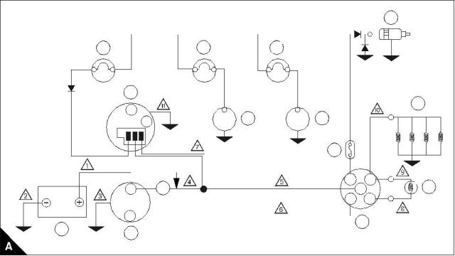
Auto shutdown wiring diagram
55 Amp alternator charge lamp
Note: Alternator charge lamp rating: 12V - 2.2W at 850 rev/min.
When the engine is at rest the alternator charge lamp is illuminated via the battery and it extinguishes when
the alternator operates.
The use of a lower wattage bulb than the above will increase the speed at which self excitation occurs upon
initial run up, e.g. a charge lamp with a lower wattage bulb will have a rating of 12V - 1.2W at 1300 rev/min.
Pin number
connector
Wire colour
Connection
Red
Key Switch - AC
Orange
Red / Black
Brown
Key Switch - 50
Solenoid
Oil Pressure Switch
Water Temperature Switch
Ground (earth)
Blue
Black
3
4
2
5
1
6
Workshop Manual, TPD 1377E, issue 4
125
This document has been printed from SPI². Not for Resale
![]()
![]()


14
100 Series
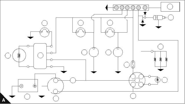
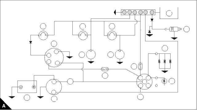
Auto shutdown wiring diagram 14 and 15 amp alternator - 102-05, 103-07, 103-10
Auto shutdown operation conditions
If the conditions below last for more than 10 seconds during the start operation, the engine will shut down.
If the conditions below last for more than 2 seconds while the engine is operated, the engine will shut down.
Warning! There is no protection against low water levels.
Conditions
Water temperature switch: If the water temperature exceeds 105 °C ± 4 °C.
Oil Pressure Switch: If the oil pressure falls below 0,3 kgf/cm² (4.27 lbf/in²).
1 Alternator warning lamp
2 Regulator
9 Thermostat switch
10 Fuse
3 Alternator
11 Key switch
4 Battery
12 Glow signal
5 Starter motor
13 Glow plugs
6 Oil pressure warning lamp
7 Oil pressure switch (1)
8 Water temperature warning lamp
14 Solenoid switch
15 Auto shutdown device
16 A delayed fuse can be fitted if desired
(1) Max current draw for standard oil pressure switch is 0.42 amps (5 Watt lamp max).
= Diode. Capacity: Current 3 amp. Reverse Voltage: 600V. (This is mandatory).
6
4
5
1
2
3
15
14
1
6
8
Sb
Sb
G
Y
R
B
13
7
9
3
2
10
AC
50
17
B
16
30
12
19
S
11
4
5
126
Workshop Manual, TPD 1377E, issue 4
This document has been printed from SPI². Not for Resale
![]()
![]()
![]()
14
100 Series
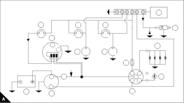
Auto shutdown wiring diagram 40 amp alternator - 103-10
(when fitted with optional alternator)
Auto shutdown operation symptoms
If the conditions below last for more than 10 seconds during the start operation, the engine will shut down.
If the conditions below last for more than 2 seconds while the engine is operated, the engine will shut down.
Warning! There is no protection against low water levels.
Conditions
Water temperature switch: If the water temperature exceeds 105 °C ± 4 °C.
Oil Pressure Switch: If the oil pressure falls below 0,3 kgf/cm² (4.27 lbf/in²).
1 Alternator warning lamp
2 Alternator
9 Key switch
10 Glow signal
3 Battery
11 Glow plugs
4 Starter motor
12 Fuse
5 Oil pressure warning lamp
6 Oil pressure switch (1)
7 Water temperature warning lamp
8 Thermostat switch
13 Fuse
14 Solenoid switch
15 Auto shutdown device
16 A delayed fuse can be fitted if desired
(1) Max current draw for standard oil pressure switch is 0.42 amps (5 Watt lamp max).
= Diode. Capacity: Current 3 amp. Reverse Voltage: 600V. (This is mandatory).
6
4
5
1
2
3
15
1
5
7
14
2
11
6
8
N
F
B
13
12
AC
17
19
B
16
30
10
50
S
3
9
4
Workshop Manual, TPD 1377E, issue 4
127
This document has been printed from SPI². Not for Resale
![]()
![]()
![]()

14
100 Series
Auto shutdown wiring diagram 40 amp alternator - 103-13
Auto shutdown operation symptoms
If the conditions below last for more than 10 seconds during the start operation, the engine will shut down.
If the conditions below last for more than 2 seconds while the engine is operated, the engine will shut down.
Warning! There is no protection against low water levels.
Conditions
Water temperature switch: If the water temperature exceeds 105 °C ± 4 °C.
Oil Pressure Switch: If the oil pressure falls below 0,3 kgf/cm² (4.27 lbf/in²).
1 Alternator warning lamp
2 Alternator
9 Key switch
10 Glow signal
3 Battery
11 Glow plugs
4 Starter motor
12 Fuse
5 Oil pressure warning lamp
6 Oil pressure switch (1)
7 Water temperature warning lamp
8 Thermostat switch
13 Fuse
14 Solenoid switch
15 Auto shutdown device
16 A delayed fuse can be fitted if desired
(1) Max current draw for standard oil pressure switch is 0.42 amps (5 Watt lamp max).
= Diode. Capacity: Current 3 amp. Reverse Voltage: 600V. (This is mandatory).
6
4
5
1
2
3
15
1
5
7
14
2
11
N
6
8
N
F
B
13
12
AC
17
19
B
16
30
10
50
S
9
3
4
128
Workshop Manual, TPD 1377E, issue 4
This document has been printed from SPI². Not for Resale
![]()
![]()
![]()
14
100 Series
Auto shutdown wiring diagram 40 amp alternator - 103-15, 104-19, 104-22
Auto shutdown operation symptoms
If the conditions below last for more than 10 seconds during the start operation, the engine will shut down.
If the conditions below last for more than 2 seconds while the engine is operated, the engine will shut down.
Warning! There is no protection against low water levels.
Conditions
Water temperature switch: If the water temperature exceeds 105 °C ± 4 °C.
Oil Pressure Switch: If the oil pressure falls below 0,3 kgf/cm² (4.27 lbf/in²).
1 Alternator warning lamp
2 Alternator
9 Key switch
10 Glow signal
3 Battery
11 Glow plugs
4 Starter motor
12 Fuse
5 Oil pressure warning lamp
6 Oil pressure switch (1)
7 Water temperature warning lamp
8 Thermostat switch
13 Solenoid switch
14 Auto shutdown device
15 A delayed fuse can be fitted if desired
(1) Max current draw for standard oil pressure switch is 0.42 amps (5 Watt lamp max).
= Diode. Capacity: Current 3 amp. Reverse Voltage: 600V. (This is mandatory).
6
4
5
1
2
3
14
1
5
7
13
2
W
11
F
6
8
B
IND
12
55A 80/0.4 (10)
AC
17
19
B
15
30
10
50
S
3
9
4
Workshop Manual, TPD 1377E, issue 4
129
This document has been printed from SPI². Not for Resale
![]()
![]()
![]()
This page is intentionally blank
This document has been printed from SPI². Not for Resale
100 Series
15
Auxiliary equipment
15
Radiator Anti-Vibration mountings
A new radiator mounting (part number 2638D017) has been introduced from engine serial number
KD-----141489H for 103-10 engines, and from engine serial number KE\KF\KR-----954917H for 103-15, 104-
19, and 104-22 engines.
Caution: New mountings should not be mixed with older mountings. The new mounting is identified with a
yellow mark, the old mounting is identified with an orange mark. If it is necessary to replace any of the three
radiator anti-vibration mountings, then all three should be replaced at the same time using the new
specification mounting.
Note: All mountings supplied via Perkins Parts Distribution Centre (PDC), Irlam, England will be to the latest
specification.
Workshop Manual, TPD 1377E, issue 4
131
This document has been printed from SPI². Not for Resale
![]()
![]()
![]()
This page is intentionally blank
This document has been printed from SPI². Not for Resale
100 Series
16
Special tools
16
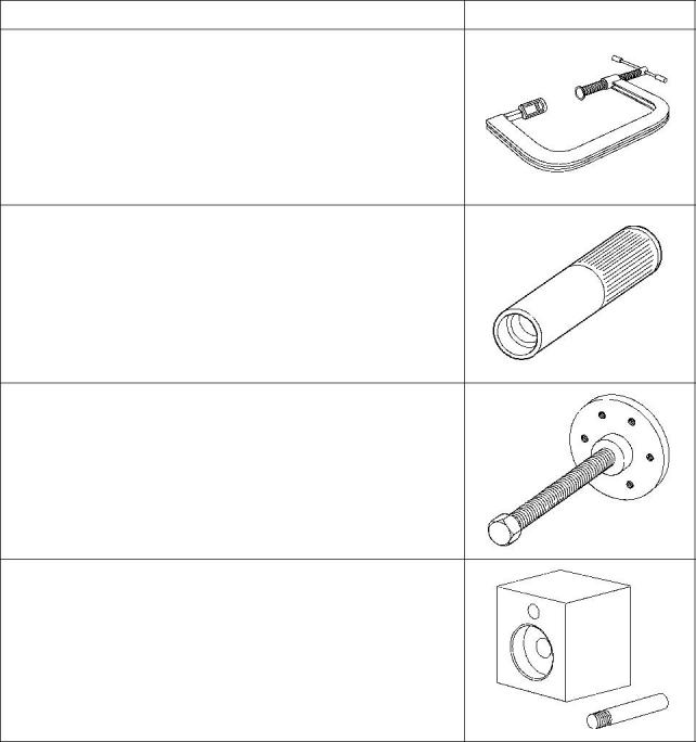
Special tools list
These tools are available through your nearest Perkins Dealer/Distributor.
Description
Illustration
Valve spring remover
Part number 21825663
Valve stem seal replacer
102-05, 103-07: Part number 21825622
103-10, 103-13, 103-15, 104-19, 104-22: Part number 21825623
Crankshaft pulley remover
Part number 21825619
Idler hub assembly tool
102-05, 103-07: Part number 21825624
103-10: Part number 21825625
103-13, 103-15, 104-19, 104-22: Part number 21825626
Workshop Manual, TPD 1377E, issue 4
133
This document has been printed from SPI². Not for Resale
![]()
![]()
16
100 Series
Description
Illustration
Fuel pump spill pipe
Part number: 21825680
Front oil seal protector
102-05, 103-07, 103-10: Part number 21825620
103-13, 103-15, 104-19, 104-22: Part number 21825621
134
Workshop Manual, TPD 1377E, issue 4
This document has been printed from SPI². Not for Resale
![]()
![]()

Models 102-05, 103-07, 103-10, 103-13, 103-15, 104-19,
104-22
WORKSHOP MANUAL
102-05
Two cylinder diesel engines
Three cylinder diesel engines
103-07
103-10
103-13
103-15
104-19
104-22
Four cylinder diesel engines
Publication TPD 1377E, Issue 4
© Proprietary information of Perkins Engines Company Limited, all rights reserved.
The information is correct at the time of print.
Published in September 2003 by Technical Publications.
i
This document has been printed from SPI². Not for Resale