 English
 Espaol
 Franais
 阿拉伯
阿拉伯 中文
中文 Deutsch
 Italiano
 Português
 日本
日本 韩国
韩国 български
 hrvatski
 esky
esky Dansk
Dansk Nederlands
 suomi
suomi Ελληνικ
 印度
印度 norsk
norsk Polski
 Roman
Roman русский
 Svenska
Perkins珀金斯100维修手册供应商,Perkins珀金斯100维修手册技术价格规格咨询服务,Perkins珀金斯100维修手册零配件供应,Perkins珀金斯100维修手册售后服务中心,Perkins珀金斯100维修手册,Perkins珀金斯100维修手册详细的技术参数,

产品中心
Perkins珀金斯100维修手册(英文)一
详细描述
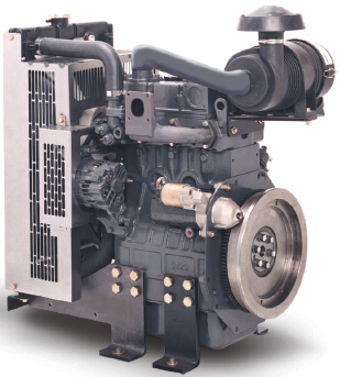
Perkins 100 Series
Models 102-05, 103-07, 103-10, 103-13, 103-15, 104-19,
104-22
WORKSHOP MANUAL
102-05
Two cylinder diesel engines
Three cylinder diesel engines
103-07
103-10
103-13
103-15
104-19
104-22
Four cylinder diesel engines
Publication TPD 1377E, Issue 4
© Proprietary information of Perkins Engines Company Limited, all rights reserved.
The information is correct at the time of print.
Published in September 2003 by Technical Publications.
i
This document has been printed from SPI². Not for Resale
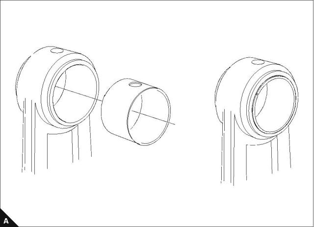
Small end bush
To remove and to fit
Operation 4-7
Special requirements
Clearance mm (in)
Engine model
Standard
Service limit
0,1 (0.004)
0,1 (0.004)
0,1 (0.004)
102-05, 103-07
0,013 - 0,028 (0.00051 - 0.00110)
0,008 - 0,023 (0.00031 - 0.00091)
0,010 - 0,025 (0.00040 - 0.00099)
103-10
103-13, 103-15, 104-19, 104-22
Calculate the clearance between the small end bush and the gudgeon pin. If the clearance exceeds the service
limit, renew.
Workshop Manual, TPD 1377E, issue 4
55
This document has been printed from SPI². Not for Resale
![]()
![]()
![]()
![]()

4
100 Series
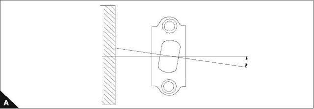
Connecting rod
To inspect
Operation 4-8
Special requirements
Dimension mm (in)
Standard
Service limit
Distortion for 100 (3.937)
Parallel for 100 (3.937)
Less than 0,08 (0.0031)
0,20 (0.0079) max
0,15 (0.0059) max
Less than 0,05 (0.0020)
56
Workshop Manual, TPD 1377E, issue 4
This document has been printed from SPI². Not for Resale
![]()
![]()
![]()
![]()


100 Series
5
Crankshaft assembly
5
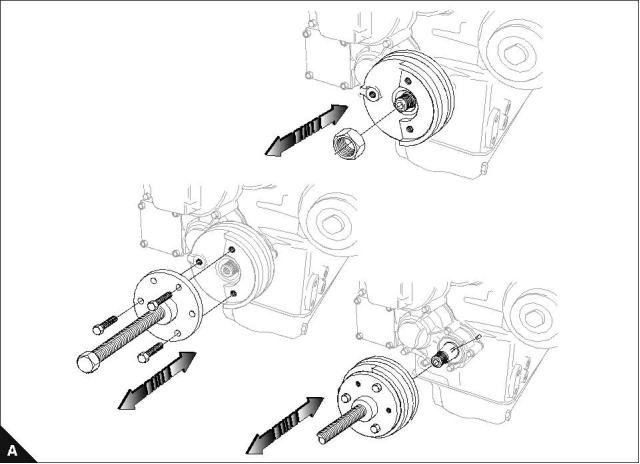
Crankshaft pulley
To remove and to fit
Operation 5-1
Special requirements
Special tools
Description
Torque Nm (lbf ft) kgf m
Part number
102-05, 103-07
93 (69) 9,5
123 (91) 12,5
304 (224) 31
103-10
Crankshaft pulley remover
21825619
103-13, 103-15, 104-19, 104-22
Note: Store the key (A1) in a safe place until assembly.
Workshop Manual, TPD 1377E, issue 4
57
This document has been printed from SPI². Not for Resale
![]()
![]()
![]()
![]()

5
100 Series
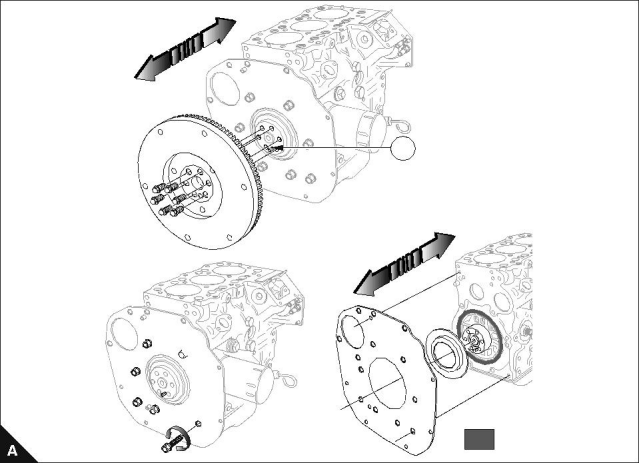
Flywheel, backplate and oil seal
To remove and to fit
Operation 5-2
Special requirements
POWERPART products
Description
Part number
Silicone RTV sealing and jointing compound
1861108
Flywheel setscrews : Torque Nm (lbf ft) kgf m
Backplate setscrews : Torque Nm (lbf ft) kgf m
102-05, 103-07
73 (54) 7,4
102-05, 103-07
15 (11) 1,5
50 (37) 5,1
15 (11) 1,5
103-10
73 (54) 7,4
73 (54) 7,4
103-10
103-13, 103-15, 104-19, 104-22
103-13, 103-15, 104-19, 104-22
Notes:
To remove and fit the flywheel, see Operation 13-1.
On assembly, apply Powerpart silicone RTV sealing and jointing compound to the block (around screw
holes) before the backplate is fitted.
103-10, 103-13 and 103-15 engines only: Remember the position of the dowel (A1).
1
POWERPART silicone
gasket sealant
58
Workshop Manual, TPD 1377E, issue 4
This document has been printed from SPI². Not for Resale
![]()
![]()
![]()
![]()
![]()
![]()
![]()


5
100 Series
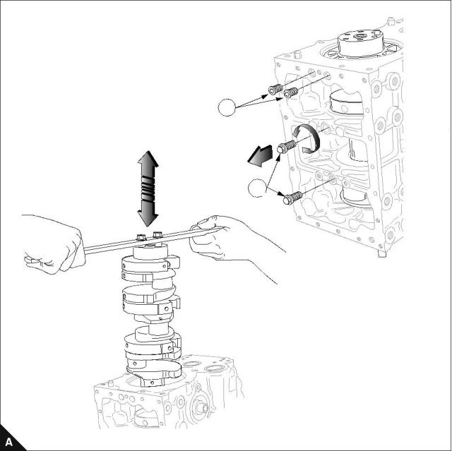
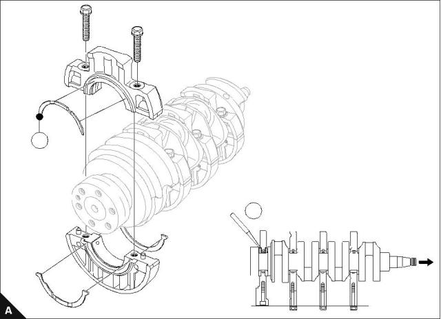
Crankshaft retainer setscrews and crankshaft
To remove and to fit
Operation 5-3
Special requirements
Hex hole setscrews (A1) : Torque Nm (lbf ft) kgf m
Hex setscrews (A2) : Torque Nm (lbf ft) kgf m
102-05, 103-07, 103-10
27 (20) 2,7
27 (20) 2,7
102-05, 103-07, 103-10
27 (20) 2,7
51 (38) 5,2
103-13, 103-15, 104-19, 104-22
103-13, 103-15, 104-19, 104-22
Check that the oil ways of the bearings match up with the oil ways in the block.
Caution: Before removal and fitting of the crankshaft ensure that the pressure relief valve has been removed.
Notes:
For emissions approved engines. The fuel adjustment screw must not be altered from the original setting.
The maximum No Load Speed must be checked after assembly.
If a new crankshaft is fitted, see Operation 3-13.
Continued
Workshop Manual, TPD 1377E, issue 4
59
This document has been printed from SPI². Not for Resale
![]()
![]()
![]()
![]()
![]()
![]()
![]()

5
100 Series
1
2
60
Workshop Manual, TPD 1377E, issue 4
This document has been printed from SPI². Not for Resale
![]()
![]()
5
100 Series
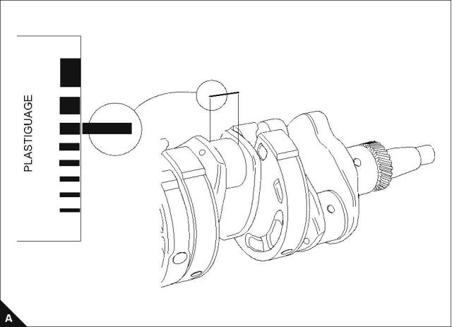
Bearing clearance
To check
Operation 5-4
Special requirements
Clearance mm (in)
Engine model
Standard
Service limit
0,20 (0.0079)
0,20 (0.0079)
0,20 (0.0079)
102-05, 103-07
0,031 - 0,079 (0.00122 - 0.00311)
0,035 - 0,083 (0.00138 - 0.00327)
0,035 - 0,085 (0.00138 - 0.00335)
103-10
103-13, 103-15, 104-19, 104-22
Use Plastigauge® to check the bearing clearance.
Tighten the main bearings to the torque settings given in Operation 5-5 for two and three cylinder engines or
Operation 5-6 for four cylinder engines.
1.0
2.0
2.5
3.0
4.0
5.0
6.0
7.0
INCH
Workshop Manual, TPD 1377E, issue 4
61
This document has been printed from SPI². Not for Resale
![]()
![]()
![]()
![]()

5
100 Series
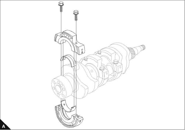
Main bearings
To dismantle and to assemble (two and three cylinder engines)
Operation 5-5
Special requirements
Bearing holder (Aluminium) : Thickness mm (in)
Torque Nm (lbf ft) kgf m
Standard
Service limit
102-05, 103-07, 103-10
Aluminium Bearings
22 (16) 2,2
21,85 - 21,95 (0.8602 - 0.8641)
21,6 (0.8503)
102-05, 103-07, 103-10
Cast Iron Bearings
27 (19.9) 2,7
N/A
N/A
End Float : Clearance mm (in)
Engine model
Standard
Service limit
0,50 (0.0197)
0,50 (0.0197)
102-05, 103-07
103-10
0,10 - 0,30 (0.0040 - 0.0120)
0,05 - 0,30 (0.0020 - 0.0120)
1 Identify position of bearing carriers on shaft.
2 Install bearing carriers on the crankshaft ensuring oil holes align with feed holes in cylinder block.
3 Check end float.
4 Check number 2 bearing holder on 102-05 engines and number 3 bearing holder on 103-07 and 103-10
engines for wear, poor contact, look burnt or other defects. Defective bearing holders must be renewed.
Notes:
For emissions approved engines. The fuel adjustment screw must not be altered from the original setting.
The maximum No Load Speed must be checked after assembly.
62
Workshop Manual, TPD 1377E, issue 4
This document has been printed from SPI². Not for Resale
![]()
![]()
![]()
![]()
![]()
![]()


5
100 Series
To dismantle and to assemble (four cylinder engines)
Operation 5-6
Special requirements
Torque Nm (lbf ft) kgf m
103-13, 103-15, 104-19, 104-22
51 (38) 5,2
End float : Clearance mm (in)
Thrust washer : Thickness mm (in)
Standard
Service limit
Standard
Service limit
0,10 - 0,40 (0.0040 - 0.0160)
0,50 (0.0197) max
2,95 - 3,00 (0.1161 - 0.1181)
2,80 (0.1102) max
1 Identify position of bearing carriers on shaft.
2 Install bearing carriers on shaft ensuring oil holes align with feed holes in cylinder block.
3 Check end float clearance (A2).
Note: Ensure that the thrust washers are aligned correctly, and are fitted with their oil grooves towards the
crankshaft.
4 Check the thrust washers for wear, poor contact, look burnt, or have any other defects. Defective washers
must be renewed.
Note: Item (A1) is only used on 104-19 and 104-22 engines.
1
2
Workshop Manual, TPD 1377E, issue 4
63
This document has been printed from SPI². Not for Resale
![]()
![]()
![]()
![]()
![]()

This page is intentionally blank
This document has been printed from SPI². Not for Resale
100 Series
6
Timing case and drive assembly
6
Fuel injection pump
To remove and to fit
Operation 6-1
Special requirements
Torque Nm (lbf ft) kgf m
Solenoid
17 (12) 1,7
When the shim (A1) is not required, assemble using a 0,5 mm bead of silicone sealant.
Note: Blank off the connections of the fuel injection pump until assembly.
1
Workshop Manual, TPD 1377E, issue 4
65
This document has been printed from SPI². Not for Resale
![]()
![]()
![]()
![]()
![]()
6
100 Series
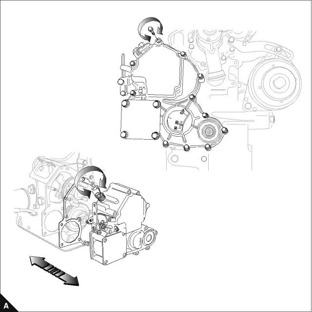
Timing cover
To remove and to fit
Operation 6-2
For crankshaft pulley removal refer to Operation 5-1.
Notes:
Make sure that the governor springs are correctly attached before the timing cover is fitted, see Operation
6-14.
On assembly hold arm clockwise.
After fitting the timing cover, look through the ESOS mounting holeand check that the linkage moves
correctly when the throttle lever on the fuel injection pump is operated.
For emissions approved engines. The fuel adjustment screw should not be altered from original setting.
The Maximum No Load Speed must be checked after assembly.
If a new timing case is fitted, a new emissions label must be fitted.
66
Workshop Manual, TPD 1377E, issue 4
This document has been printed from SPI². Not for Resale
![]()
![]()
![]()
![]()
![]()
![]()
![]()
![]()
![]()
![]()
6
100 Series
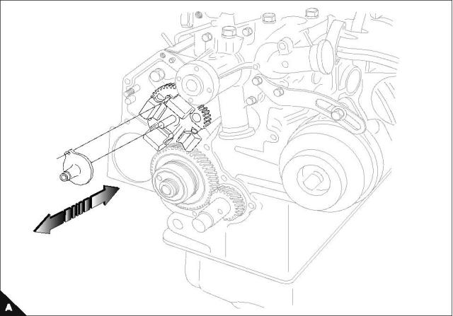
Slider
To remove and to fit
Operation 6-3
Workshop Manual, TPD 1377E, issue 4
67
This document has been printed from SPI². Not for Resale
![]()
![]()
![]()
![]()
6
100 Series
Camshaft retainer plate
To remove and to fit
Operation 6-4
Special requirements
Torque Nm (lbf ft) kgf m
Camshaft retainer plate setscrews
11 (8) 1,1
Notes:
For emissions approved engines. The fuel adjustment screw must not be altered from the original setting.
The maximum No Load Speed must be checked after assembly.
68
Workshop Manual, TPD 1377E, issue 4
This document has been printed from SPI². Not for Resale
![]()
![]()
![]()
![]()
![]()
![]()
![]()
6
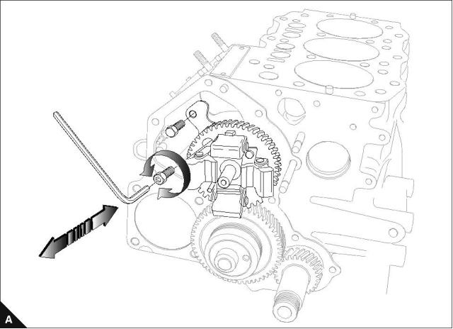
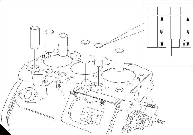
100 Series
Camshaft and cam followers
To remove
Operation 6-5
Caution: Remove fuel lift pump and all the cam followers before removing the camshaft.
Workshop Manual, TPD 1377E, issue 4
69
This document has been printed from SPI². Not for Resale
![]()
![]()
![]()
![]()
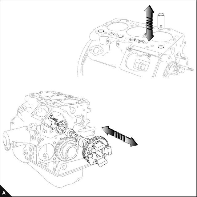
6
100 Series
To fit
Operation 6-6
Cautions:
The new camshaft is not interchangeable with the old camshaft.
If a new camshaft is fitted, new cam followers of the correct type must be fitted as well.
From engine serial number 333367J the camshaft and the cam followers fitted to the 103-07 engine have
changed.
The width of the injection cams for N°2 and N°3 cylinders have been increased by 0,5 mm.
To prevent interference with the wider injection cam on the camshaft, the diameter of the tappet end of the
exhaust cam follower for N°1 cylinder has been decreased by 1,0 mm to 17 mm.
Tappet
Ø 18
Ø 18
Ø 17
Current
New
120116100
120116180
B
70
Workshop Manual, TPD 1377E, issue 4
This document has been printed from SPI². Not for Resale
![]()
![]()
![]()
![]()
![]()
![]()
6
100 Series
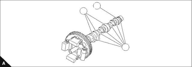
Camshaft assembly
To inspect
Operation 6-7
Cam height (intake and exhaust cams) (A1)
Engine model
Height mm (in)
Standard
Service limit
26,1 (1.028)
26,1 (1.028)
33,7 (1.327)
102-05, 103-07
26,565 - 26,620 (1.04590 - 1.04803)
26,445 - 26,500 (1.04114 - 1.04330)
34,065 - 34,120 (1.34114 - 1.34330)
103-10
103-13, 103-15, 104-19, 104-22
Height of cam for injection pump (A2)
Engine model
Height mm (in)
Standard
Service limit
34,3 (1.351)
33,8 (1.331)
41,8 (1.645)
102-05, 103-07
34,480 - 34,520 (1.3575 - 1.3591)
33,940 - 34,060 (1.3362 - 1.34094)
41,940 - 42,060 (1.65120 - 1.65590)
103-10
103-13, 103-15, 104-19, 104-22
Height of cam for fuel feed pump (A3)
Engine model
Height mm (in)
Standard
Service limit
27,0 (1.063)
30,0 (1.181)
102-05, 103-07, 103-10
27,900 - 28,000 (1.09842 - 1.10236)
31,900 - 32,000 (1.25590 - 1.25984)
103-13, 103-15, 104-19, 104-22
3
2
1
Workshop Manual, TPD 1377E, issue 4
71
This document has been printed from SPI². Not for Resale
![]()
![]()
![]()
![]()


6
100 Series
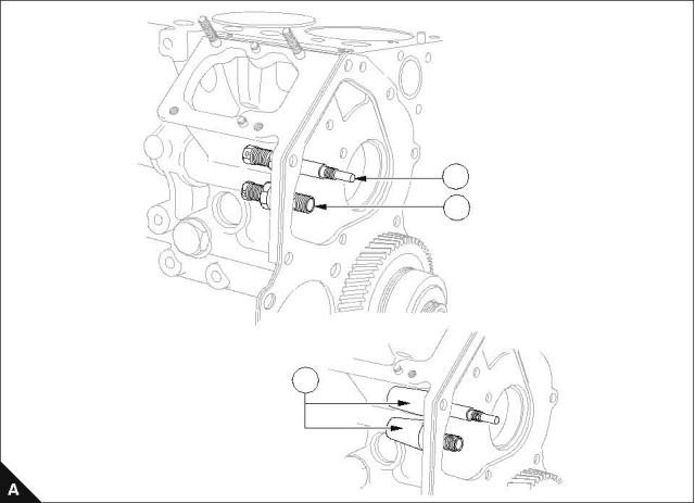
Max fuel screw and max speed screw
To locate
Operation 6-8
Notes:
The max fuel screw (A1) and max speed screw (A2) should not be adjusted by the operator.
An anti tamper device (A3) may be fitted. Where this device is present, see Operation 6-9.
If adjustment of the maximum fuel screw or the no load speed is necessary, the adjustment must be done
on an engine test facility by personnel approved by Perkins Engines Company Ltd.
1
2
3
72
Workshop Manual, TPD 1377E, issue 4
This document has been printed from SPI². Not for Resale
![]()
![]()
![]()
![]()
![]()
![]()
![]()
6
100 Series
To remove and to fit
Operation 6-9
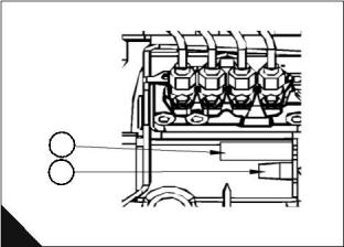
A requirement of emissions legislation is that access to adjustments (A1, A2) that affect the engine's exhaust
emissions is limited to personnel approved by Perkins Engines Company Ltd.
The fuel adjustment screw (B2) and maximum speed adjustment (B5) are affected. The fuel adjustment screw
has a tamper resistant body (B1) fitted over the screw and the maximum speed adjustment is protected by a
tamper evident plastic cap (B4).
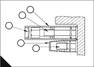
To remove the tamper resistant body
1 Strike the tamper resistant device metal body (B1) with a suitable cold chisel approximately 10-15 mm from
the cylinder block flange. This will deform the body against the screw lock nut. This operation is necessary until
the metal tube cannot freely rotate around the fuel adjustment screw.
2 Rotate the metal body and the fuel adjustment screw together using a pair of pliers at the D-plug (B3) end
of the tube.
3 Remove the fuel adjustment screw (B2) as a single assembly completely from the cylinder block.
As the removal procedure for the original fuel adjustment screw and tamper resistant device body will cause
permanent damage to both these items, replacements must be obtained from PDC Irlam.
To re-fit a new fuel screw and service tamper resistant body
1 The fuel adjustment screw assembly (B2) may vary according to the engine build code. The appropriate
replacement must be obtained from PDC Irlam.
1
2
3
1
2
4
5
A
B
Continued
Workshop Manual, TPD 1377E, issue 4
73
This document has been printed from SPI². Not for Resale
![]()
![]()
![]()
![]()
6
100 Series
A special service version of the tamper evident body (D) must be fitted when a new fuel screw is fitted. A kit
part number U5MK0619 is available from PDC. This kit will be supplied only to permitted personnel and must
not be supplied to end users. A groove (D4) around the circumference of the tamper evident body is used to
identify it as a service part.
2 Fit the fuel adjustment screw assembly (C3) to the engine ensuring that there is a metal snap ring (C1)
located in the lock nut groove and a o-ring (C2) fitted.
3 On a suitable calibrated test facility, reset the engine performance parameters to the certified specification
indicated on the engine's emissions control information label mounted on the timing case.
4 Having set the full load fuel delivery to the certified specification and ensuring the lock nut is correctly
tightened, insert the D-plug (D2) into the service tamper resistant body (D3) at the opposite end of the internal
groove (D1). Fit the new service tamper resistant body assembly (D) over the fuel adjustment screw.
5 Tap on the tube until the internal groove (D1) in the body engages over the metal snap ring (C1) in the lock
nut.
To remove and re-fit the tamper evident maximum engine speed cap
The maximum speed adjustment has a plastic cap (B4) fitted by Perkins. The length of this fitted cap will be
either 22mm or 30mm in length depending on the original protrusion of the maximum speed adjustment screw
(B5). The cap is pressed by hand onto the adjustment screw and an internal lip locates into a groove on the
lock nut.
1 Remove the plastic cap (B4) from the maximum speed bolt (B5) with a suitable lever, taking care not to
damage the seal between the cylinder block and the locknut.
2 Make the necessary adjustment to maximum (no load) engine speed by rotating bolt clockwise to reduce
speed and anti-clockwise to increase speed with the engine throttle lever fully open.
Note: The only permitted adjustment to the maximum engine speed is to correct the speed in accordance with
the high idle speed shown on the emissions compliance label mounted on the engine timing case.
3 After adjustment to within the certified maximum speed range, a new service cap of the appropriate length
can be obtained from PDC Irlam. The replacement service cap will be red in colour part number 131276440 -
30mm length or 131276450 - 22 mm length. This cap will be supplied only to permitted personnel and must
not be supplied to end users.
4 Hand press the replacement service cap onto maximum speed bolt (C4) lock nut.
A warranty claim will not be accepted if it can be seen that an adjustment to the maximum engine speed setting
(B5) or the fuel adjustment screw (B2) has been made by personnel not approved by Perkins.
1
2
3
4
1
3
2
4
c
C
D
74
Workshop Manual, TPD 1377E, issue 4
This document has been printed from SPI². Not for Resale