 English
 Espaol
 Franais
 阿拉伯
阿拉伯 中文
中文 Deutsch
 Italiano
 Português
 日本
日本 韩国
韩国 български
 hrvatski
 esky
esky Dansk
Dansk Nederlands
 suomi
suomi Ελληνικ
 印度
印度 norsk
norsk Polski
 Roman
Roman русский
 Svenska
我们是***的珀金斯Perkins100维修维护供应服务商.我们可提供珀金斯Perkins100维修维护销售维修保养零配件服务.珀金斯Perkins100维修维护想要更多的类型,请现在联系湖南英珀威机械有限公司!

产品中心
珀金斯Perkins100维修维护车间手册(英文)
详细描述
Perkins 100 Series
Models 102-05, 103-07, 103-10, 103-13, 103-15, 104-19,
104-22
WORKSHOP MANUAL
102-05
Two cylinder diesel engines
Three cylinder diesel engines
103-07
103-10
103-13
103-15
104-19
104-22
Four cylinder diesel engines
Publication TPD 1377E, Issue 4
© Proprietary information of Perkins Engines Company Limited, all rights reserved.
The information is correct at the time of print.
Published in September 2003 by Technical Publications.
i
This document has been printed from SPI². Not for Resale
![]()
![]()
This publication is written in
Perkins Approved Clear English
Chapters
1 General information
2 Specifications
3 Cylinder head assembly
4 Piston and connecting rod assemblies
5 Crankshaft assembly
6 Timing case and drive assembly
7 Cylinder block assembly
8 Engine timing
9 Aspiration system
10 Lubrication system
11 Fuel system
12 Cooling system
13 Flywheel and housing
14 Electrical equipment
15 Auxiliary equipment
16 Special tools
The following pages contain a detailed table of contents
ii
This document has been printed from SPI². Not for Resale
![]()
![]()
![]()

100 Series
Contents
1 General information
Introduction .. ... ... ... ... ... ... ... ... ... ... ... ... ... ... ... ... ... ... ... ... ... ... ... ... ... ... ... ... ... ... ... ... ... ... ... 1
Safety precautions . ... ... ... ... ... ... ... ... ... ... ... ... ... ... ... ... ... ... ... ... ... ... ... ... ... ... ... ... ... ... ... ... 2
Engine preservation .. ... ... ... ... ... ... ... ... ... ... ... ... ... ... ... ... ... ... ... ... ... ... ... ... ... ... ... ... ... ... ... 4
POWERPART recommended consumable products ... ... ... ... ... ... ... ... ... ... ... ... ... ... ... ... 5
Engine I.D. location ... ... ... ... ... ... ... ... ... ... ... ... ... ... ... ... ... ... ... ... ... ... ... ... ... ... ... ... ... ... ... ... 7
Engine views - 3 cylinder front and rear ... ... ... ... ... ... ... ... ... ... ... ... ... ... ... ... ... ... ... ... ... ... 8
Engine views - 2 cylinder front and 4 cylinder front ... ... ... ... ... ... ... ... ... ... ... ... ... ... ... ... 9
Engine lift equipment ... ... ... ... ... ... ... ... ... ... ... ... ... ... ... ... ... ... ... ... ... ... ... ... ... ... ... ... ... ... .. 10
Viton seals . ... ... ... ... ... ... ... ... ... ... ... ... ... ... ... ... ... ... ... ... ... ... ... ... ... ... ... ... ... ... ... ... ... ... ... .. 11
Safety cautions, when an engine is cleaned ... ... ... ... ... ... ... ... ... ... ... ... ... ... ... ... ... ... ... .. 11
Engines that conform to Emissions Levels ... ... ... ... ... ... ... ... ... ... ... ... ... ... ... ... ... ... ... .. 11
Compression test data . ... ... ... ... ... ... ... ... ... ... ... ... ... ... ... ... ... ... ... ... ... ... ... ... ... ... ... ... ... .. 12
Publication Type, TPD 1377E, issue 4
iii
This document has been printed from SPI². Not for Resale
![]()
![]()
100 Series
2 Specifications
Basic engine data . ... ... ... ... ... ... ... ... ... ... ... ... ... ... ... ... ... ... ... ... ... ... ... ... ... ... ... ... ... ... ... ... 13
Thread Sealant ... ... ... ... ... ... ... ... ... ... ... ... ... ... ... ... ... ... ... ... ... ... ... ... ... ... ... ... ... ... ... ... ... ... 14
Recommended torque tensions . ... ... ... ... ... ... ... ... ... ... ... ... ... ... ... ... ... ... ... ... ... ... ... ... ... 14
Data and dimensions .. ... ... ... ... ... ... ... ... ... ... ... ... ... ... ... ... ... ... ... ... ... ... ... ... ... ... ... ... ... ... 15
Injection timing .. ... ... ... ... ... ... ... ... ... ... ... ... ... ... ... ... ... ... ... ... ... ... ... ... ... ... ... ... ... ... ... ... ... 15
Cylinder bore dimensions . ... ... ... ... ... ... ... ... ... ... ... ... ... ... ... ... ... ... ... ... ... ... ... ... ... ... ... ... 16
Piston and piston ring dimensions ... ... ... ... ... ... ... ... ... ... ... ... ... ... ... ... ... ... ... ... ... ... ... ... 17
Gudgeon pin ... ... ... ... ... ... ... ... ... ... ... ... ... ... ... ... ... ... ... ... ... ... ... ... ... ... ... ... ... ... ... ... ... ... ... 18
Crankshaft deflection .. ... ... ... ... ... ... ... ... ... ... ... ... ... ... ... ... ... ... ... ... ... ... ... ... ... ... ... ... ... ... 19
Crankshaft inspection ... ... ... ... ... ... ... ... ... ... ... ... ... ... ... ... ... ... ... ... ... ... ... ... ... ... ... ... ... ... 19
Crankshaft journal diameters .. ... ... ... ... ... ... ... ... ... ... ... ... ... ... ... ... ... ... ... ... ... ... ... ... ... ... 20
Crankshaft pin diameters .. ... ... ... ... ... ... ... ... ... ... ... ... ... ... ... ... ... ... ... ... ... ... ... ... ... ... ... ... 21
Bearing holder ... ... ... ... ... ... ... ... ... ... ... ... ... ... ... ... ... ... ... ... ... ... ... ... ... ... ... ... ... ... ... ... ... ... 22
Undersize bearing shell chart .. ... ... ... ... ... ... ... ... ... ... ... ... ... ... ... ... ... ... ... ... ... ... ... ... ... ... 23
Crankshaft bearing bush ... ... ... ... ... ... ... ... ... ... ... ... ... ... ... ... ... ... ... ... ... ... ... ... ... ... ... ... ... 24
3 Cylinder head assembly
Rocker cover and inlet manifold
Operation 3-1 To remove and to fit .. ... ... ... ... ... ... ... ... ... ... ... ... ... ... ... ... ... ... ... ... ... ... ... ... 25
Rocker assembly
Operation 3-2 To remove and to fit .. ... ... ... ... ... ... ... ... ... ... ... ... ... ... ... ... ... ... ... ... ... ... ... ... 26
Rocker shaft (102-05, 103-07, 103-10)
Operation 3-3 To dismantle, to inspect and to assemble .. ... ... ... ... ... ... ... ... ... ... ... ... ... ... 27
Rocker shaft (103-13, 103-15, 104-19, 104-22)
Operation 3-4 To dismantle, to inspect and to assemble .. ... ... ... ... ... ... ... ... ... ... ... ... ... ... 28
Fan and mounting
Operation 3-5 To remove ... ... ... ... ... ... ... ... ... ... ... ... ... ... ... ... ... ... ... ... ... ... ... ... ... ... ... ... ... 29
iv
Publication Type, TPD 1377E, issue 4
This document has been printed from SPI². Not for Resale
![]()
![]()
100 Series
Exhaust manifold and gasket
Operation 3-6 To remove and to fit ... ... ... ... ... ... ... ... ... ... ... ... ... ... ... ... ... ... ... ... ... ... ... ... .. 30
Fuel injection pipes / fuel return pipes
Operation 3-7 To remove and to fit ... ... ... ... ... ... ... ... ... ... ... ... ... ... ... ... ... ... ... ... ... ... ... ... .. 31
Oil pipes
Operation 3-8 To remove and to fit ... ... ... ... ... ... ... ... ... ... ... ... ... ... ... ... ... ... ... ... ... ... ... ... .. 32
Atomisers
Operation 3-9 To remove and to fit ... ... ... ... ... ... ... ... ... ... ... ... ... ... ... ... ... ... ... ... ... ... ... ... .. 33
Busbar / glowplugs
Operation 3-10 To remove and to fit . ... ... ... ... ... ... ... ... ... ... ... ... ... ... ... ... ... ... ... ... ... ... ... .. 34
Head bolts
Operation 3-11 To remove and to fit . ... ... ... ... ... ... ... ... ... ... ... ... ... ... ... ... ... ... ... ... ... ... ... .. 35
Cylinder head gasket
Operation 3-12 To remove and to fit . ... ... ... ... ... ... ... ... ... ... ... ... ... ... ... ... ... ... ... ... ... ... ... .. 36
Operation 3-13 To select the correct thickness of cylinder head gasket ... ... ... ... ... ... ... .. 37
Head bolts - all variants
Operation 3-14 Tightening sequence ... ... ... ... ... ... ... ... ... ... ... ... ... ... ... ... ... ... ... ... ... ... ... .. 38
Valve and valve springs
Operation 3-15 To remove and to fit . ... ... ... ... ... ... ... ... ... ... ... ... ... ... ... ... ... ... ... ... ... ... ... .. 39
Valve spring
Operation 3-16 To inspect ... ... ... ... ... ... ... ... ... ... ... ... ... ... ... ... ... ... ... ... ... ... ... ... ... ... ... ... .. 40
Valve stem diameter and thickness of valve head
Operation 3-17 To inspect ... ... ... ... ... ... ... ... ... ... ... ... ... ... ... ... ... ... ... ... ... ... ... ... ... ... ... ... .. 41
Valve guide clearance
Operation 3-18 To inspect ... ... ... ... ... ... ... ... ... ... ... ... ... ... ... ... ... ... ... ... ... ... ... ... ... ... ... ... .. 42
Cylinder head
Operation 3-19 To check the distortion of the lower face ... ... ... ... ... ... ... ... ... ... ... ... ... ... .. 43
Valve seat width
Operation 3-20 To correct ... ... ... ... ... ... ... ... ... ... ... ... ... ... ... ... ... ... ... ... ... ... ... ... ... ... ... ... .. 44
Valve depth
Operation 3-21 To correct ... ... ... ... ... ... ... ... ... ... ... ... ... ... ... ... ... ... ... ... ... ... ... ... ... ... ... ... .. 45
Publication Type, TPD 1377E, issue 4
v
This document has been printed from SPI². Not for Resale
![]()
![]()
100 Series
Valve seat contact face
Operation 3-22 Lapping ... ... ... ... ... ... ... ... ... ... ... ... ... ... ... ... ... ... ... ... ... ... ... ... ... ... ... ... ... ... 46
Valve tip clearance
Operation 3-23 To check . ... ... ... ... ... ... ... ... ... ... ... ... ... ... ... ... ... ... ... ... ... ... ... ... ... ... ... ... ... 47
4 Piston and connecting rod assemblies
Big end bearing and cap
Operation 4-1 To remove and to fit .. ... ... ... ... ... ... ... ... ... ... ... ... ... ... ... ... ... ... ... ... ... ... ... ... 49
Piston and connecting rod
Operation 4-2 To dismantle and to assemble ... ... ... ... ... ... ... ... ... ... ... ... ... ... ... ... ... ... ... ... 50
Operation 4-3 To fit ... ... ... ... ... ... ... ... ... ... ... ... ... ... ... ... ... ... ... ... ... ... ... ... ... ... ... ... ... ... ... ... 51
Piston and piston ring
Operation 4-4 To inspect . ... ... ... ... ... ... ... ... ... ... ... ... ... ... ... ... ... ... ... ... ... ... ... ... ... ... ... ... ... 52
Operation 4-5 To measure piston ring clearance ... ... ... ... ... ... ... ... ... ... ... ... ... ... ... ... ... ... 53
Piston ring and block
Operation 4-6 To inspect . ... ... ... ... ... ... ... ... ... ... ... ... ... ... ... ... ... ... ... ... ... ... ... ... ... ... ... ... ... 54
Small end bush
Operation 4-7 To remove and to fit .. ... ... ... ... ... ... ... ... ... ... ... ... ... ... ... ... ... ... ... ... ... ... ... ... 55
Connecting rod
Operation 4-8 To inspect . ... ... ... ... ... ... ... ... ... ... ... ... ... ... ... ... ... ... ... ... ... ... ... ... ... ... ... ... ... 56
5 Crankshaft assembly
Crankshaft pulley
Operation 5-1 To remove and to fit .. ... ... ... ... ... ... ... ... ... ... ... ... ... ... ... ... ... ... ... ... ... ... ... ... 57
Flywheel, backplate and oil seal
Operation 5-2 To remove and to fit .. ... ... ... ... ... ... ... ... ... ... ... ... ... ... ... ... ... ... ... ... ... ... ... ... 58
Crankshaft retainer setscrews and crankshaft
Operation 5-3 To remove and to fit .. ... ... ... ... ... ... ... ... ... ... ... ... ... ... ... ... ... ... ... ... ... ... ... ... 59
Bearing clearance
Operation 5-4 To check ... ... ... ... ... ... ... ... ... ... ... ... ... ... ... ... ... ... ... ... ... ... ... ... ... ... ... ... ... ... 61
vi
Publication Type, TPD 1377E, issue 4
This document has been printed from SPI². Not for Resale
![]()
![]()
100 Series
Main bearings
Operation 5-5 To dismantle and to assemble (two and three cylinder engines) .. ... ... ... .. 62
Operation 5-6 To dismantle and to assemble (four cylinder engines) . ... ... ... ... ... ... ... ... .. 63
6 Timing case and drive assembly
Fuel injection pump
Operation 6-1 To remove and to fit ... ... ... ... ... ... ... ... ... ... ... ... ... ... ... ... ... ... ... ... ... ... ... ... .. 65
Timing cover
Operation 6-2 To remove and to fit ... ... ... ... ... ... ... ... ... ... ... ... ... ... ... ... ... ... ... ... ... ... ... ... .. 66
Slider
Operation 6-3 To remove and to fit ... ... ... ... ... ... ... ... ... ... ... ... ... ... ... ... ... ... ... ... ... ... ... ... .. 67
Camshaft retainer plate
Operation 6-4 To remove and to fit ... ... ... ... ... ... ... ... ... ... ... ... ... ... ... ... ... ... ... ... ... ... ... ... .. 68
Camshaft and cam followers
Operation 6-5 To remove .. ... ... ... ... ... ... ... ... ... ... ... ... ... ... ... ... ... ... ... ... ... ... ... ... ... ... ... ... .. 69
Operation 6-6 To fit . ... ... ... ... ... ... ... ... ... ... ... ... ... ... ... ... ... ... ... ... ... ... ... ... ... ... ... ... ... ... ... .. 70
Camshaft assembly
Operation 6-7 To inspect .. ... ... ... ... ... ... ... ... ... ... ... ... ... ... ... ... ... ... ... ... ... ... ... ... ... ... ... ... .. 71
Max fuel screw and max speed screw
Operation 6-8 To locate ... ... ... ... ... ... ... ... ... ... ... ... ... ... ... ... ... ... ... ... ... ... ... ... ... ... ... ... ... .. 72
Operation 6-9 To remove and to fit ... ... ... ... ... ... ... ... ... ... ... ... ... ... ... ... ... ... ... ... ... ... ... ... .. 73
Idler gear and oil pump
Operation 6-10 To remove and to fit . ... ... ... ... ... ... ... ... ... ... ... ... ... ... ... ... ... ... ... ... ... ... ... .. 75
Idler hub
Operation 6-11 To fit .. ... ... ... ... ... ... ... ... ... ... ... ... ... ... ... ... ... ... ... ... ... ... ... ... ... ... ... ... ... ... .. 76
Gear teeth backlash
Operation 6-12 To check backlash ... ... ... ... ... ... ... ... ... ... ... ... ... ... ... ... ... ... ... ... ... ... ... ... .. 77
Oil pump end float
Operation 6-13 To check .. ... ... ... ... ... ... ... ... ... ... ... ... ... ... ... ... ... ... ... ... ... ... ... ... ... ... ... ... .. 78
Governor spring
Operation 6-14 To locate and to check ... ... ... ... ... ... ... ... ... ... ... ... ... ... ... ... ... ... ... ... ... ... .. 79
Publication Type, TPD 1377E, issue 4
vii
This document has been printed from SPI². Not for Resale
![]()
![]()
100 Series
Oil seal protector
Operation 6-15 To fit . ... ... ... ... ... ... ... ... ... ... ... ... ... ... ... ... ... ... ... ... ... ... ... ... ... ... ... ... ... ... ... 80
Timing cover
Operation 6-16 To fit . ... ... ... ... ... ... ... ... ... ... ... ... ... ... ... ... ... ... ... ... ... ... ... ... ... ... ... ... ... ... ... 81
7 Cylinder block assembly
Front bush
Operation 7-1 To fit ... ... ... ... ... ... ... ... ... ... ... ... ... ... ... ... ... ... ... ... ... ... ... ... ... ... ... ... ... ... ... ... 83
Cylinder block top face
Operation 7-2 To inspect . ... ... ... ... ... ... ... ... ... ... ... ... ... ... ... ... ... ... ... ... ... ... ... ... ... ... ... ... ... 84
8 Engine timing
Fuel injection pump timing
Operation 8-1 To check timing .. ... ... ... ... ... ... ... ... ... ... ... ... ... ... ... ... ... ... ... ... ... ... ... ... ... ... 85
9 Aspiration system
Breather system
Operation 9-1 To clean and renew ... ... ... ... ... ... ... ... ... ... ... ... ... ... ... ... ... ... ... ... ... ... ... ... ... 89
10 Lubrication system
Oil filter canister
Operation 10-1 To remove and to fit ... ... ... ... ... ... ... ... ... ... ... ... ... ... ... ... ... ... ... ... ... ... ... ... 91
Pressure relief valve
Operation 10-2 To remove and to fit ... ... ... ... ... ... ... ... ... ... ... ... ... ... ... ... ... ... ... ... ... ... ... ... 92
Lubricating oil sump
Operation 10-3 To remove and to fit ... ... ... ... ... ... ... ... ... ... ... ... ... ... ... ... ... ... ... ... ... ... ... ... 93
Strainer and suction pipe
Operation 10-4 To remove and to fit ... ... ... ... ... ... ... ... ... ... ... ... ... ... ... ... ... ... ... ... ... ... ... ... 94
Lubricating oil pump
Operation 10-5 To remove, to fit and to inspect ... ... ... ... ... ... ... ... ... ... ... ... ... ... ... ... ... ... ... 95
viii
Publication Type, TPD 1377E, issue 4
This document has been printed from SPI². Not for Resale
![]()
![]()
100 Series
Oil pressure switch
Operation 10-6 To remove and to fit . ... ... ... ... ... ... ... ... ... ... ... ... ... ... ... ... ... ... ... ... ... ... ... .. 96
11 Fuel system
Atomisers
Operation 11-1 To remove ... ... ... ... ... ... ... ... ... ... ... ... ... ... ... ... ... ... ... ... ... ... ... ... ... ... ... ... .. 97
Operation 11-2 To fit . ... ... ... ... ... ... ... ... ... ... ... ... ... ... ... ... ... ... ... ... ... ... ... ... ... ... ... ... ... ... .. 98
Fuel lift pump
Operation 11-3 To remove and to fit early fuel lift pump . ... ... ... ... ... ... ... ... ... ... ... ... ... ... .. 99
Operation 11-4 To remove and to fit the latest fuel lift pump . ... ... ... ... ... ... ... ... ... ... ... ... 100
Operation 11-5 To dismantle and to assemble the early fuel lift pump ... ... ... ... ... ... ... ... 101
Fuel injection pump
Operation 11-6 To remove and to fit . ... ... ... ... ... ... ... ... ... ... ... ... ... ... ... ... ... ... ... ... ... ... ... 102
Operation 11-7 Banjo Bolt ... ... ... ... ... ... ... ... ... ... ... ... ... ... ... ... ... ... ... ... ... ... ... ... ... ... ... ... 103
Vent points
Operation 11-8 To eliminate air from the fuel system .. ... ... ... ... ... ... ... ... ... ... ... ... ... ... ... 104
12 Cooling system
Fan and mounting
Operation 12-1 To remove and to fit . ... ... ... ... ... ... ... ... ... ... ... ... ... ... ... ... ... ... ... ... ... ... ... 105
Coolant pump
Operation 12-2 To remove and to fit . ... ... ... ... ... ... ... ... ... ... ... ... ... ... ... ... ... ... ... ... ... ... ... 106
Thermostat
Operation 12-3 To remove and to fit . ... ... ... ... ... ... ... ... ... ... ... ... ... ... ... ... ... ... ... ... ... ... ... 108
Operation 12-4 To test and inspect ... ... ... ... ... ... ... ... ... ... ... ... ... ... ... ... ... ... ... ... ... ... ... ... 109
13 Flywheel and housing
Flywheel
Operation 13-1 To remove and to fit . ... ... ... ... ... ... ... ... ... ... ... ... ... ... ... ... ... ... ... ... ... ... ... 111
Operation 13-2 To inspect ... ... ... ... ... ... ... ... ... ... ... ... ... ... ... ... ... ... ... ... ... ... ... ... ... ... ... ... 112
Flywheel housing (if fitted)
Operation 13-3 To remove and to fit . ... ... ... ... ... ... ... ... ... ... ... ... ... ... ... ... ... ... ... ... ... ... ... 113
Publication Type, TPD 1377E, issue 4
ix
This document has been printed from SPI². Not for Resale
![]()
![]()
100 Series
14 Electrical equipment
Electrical shut off solenoid (ESOS)
Operation 14-1 To remove and to fit ... ... ... ... ... ... ... ... ... ... ... ... ... ... ... ... ... ... ... ... ... ... ... ..115
Alternator
Operation 14-2 To remove and to fit ... ... ... ... ... ... ... ... ... ... ... ... ... ... ... ... ... ... ... ... ... ... ... ..116
Operation 14-3 Alternator Testing ... ... ... ... ... ... ... ... ... ... ... ... ... ... ... ... ... ... ... ... ... ... ... ... ..117
Starter motor
Operation 14-4 To remove and to fit ... ... ... ... ... ... ... ... ... ... ... ... ... ... ... ... ... ... ... ... ... ... ... ..119
Operation 14-5 Starter Motor Testing .. ... ... ... ... ... ... ... ... ... ... ... ... ... ... ... ... ... ... ... ... ... ... ..120
Wiring diagram 14 and 15 amp alternator - 102-05, 103-07, 103-10 . ... ... ... ... ... ... ... ..121
Wiring diagram 40 amp alternator - 103-10 (when fitted with optional alternator) ..122
Wiring diagram 55 amp alternator - 103-15, 104-19, 104-22 ... ... ... ... ... ... ... ... ... ... ... ..123
Wiring diagram 40 amp alternator - 103-13 ... ... ... ... ... ... ... ... ... ... ... ... ... ... ... ... ... ... ... ..124
Auto shutdown wiring diagram .. ... ... ... ... ... ... ... ... ... ... ... ... ... ... ... ... ... ... ... ... ... ... ... ... ..125
Auto shutdown wiring diagram 14 and 15 amp alternator - 102-05, 103-07, 103-10 126
Auto shutdown wiring diagram 40 amp alternator - 103-10
(when fitted with optional alternator) ... ... ... ... ... ... ... ... ... ... ... ... ... ... ... ... ... ... ... ... ... ... ..127
Auto shutdown wiring diagram 40 amp alternator - 103-13 ... ... ... ... ... ... ... ... ... ... ... ..128
Auto shutdown wiring diagram 40 amp alternator - 103-15, 104-19, 104-22 ... ... ... ..129
15 Auxiliary equipment
Radiator Anti-Vibration mountings ... ... ... ... ... ... ... ... ... ... ... ... ... ... ... ... ... ... ... ... ... ... ... ..131
16 Special tools
Special tools list ... ... ... ... ... ... ... ... ... ... ... ... ... ... ... ... ... ... ... ... ... ... ... ... ... ... ... ... ... ... ... ... ..133
x
Publication Type, TPD 1377E, issue 4
This document has been printed from SPI². Not for Resale
![]()
![]()
100 Series
1
General information
1
Introduction
This Workshop Manual has been written to provide the trained technician with enough information to service
and overhaul all of the latest Perkins 100 Series engines. It has been compiled for use in conjunction with
normal workshop practice and information contained in current service bulletins. Certain accepted practices
have been purposely omitted in order to avoid repetition. For overhaul procedures the assumption is made that
the engine is removed from the application.
How to use this manual
This manual is illustration based and is divided into 16 chapters. The illustrations in each chapter follow the
sequence for the complete dismantle of a particular assembly or component. Assembly is achieved by the use
of the illustrations in reverse order from the rear of the chapter. In assembly and inspection, all parts are to be
thoroughly cleaned, lubricated, and where present, burrs and scale to be removed. Any open ports of high
precision components, e.g. fuel injection equipment that are exposed when dismantled, must be blanked off
until assembly, to prevent the ingress of foreign matter.
Where the information applies to certain types of engine only, this is indicated in the illustrations. When set
screws are fitted in "through" holes into the cylinder block, a suitable sealant should be used. In this manual,
when the "left" or "right" of the engine is referred to, it is that side of the engine when viewed from the flywheel
end.
Special tools have been made available and a list of these is given in Chapter 16. At the start of each operation
reference to the relevant special tools is made.
POWERPART consumable products are listed on page 5. At the start of each operation reference to the
necessary consumable products is made.
Data and dimensions are provided as part of each operation and also in Chapter 2.
Always use the full engine number to order new parts.
Read and remember the "Safety precautions" on page 2. They are given for your protection and must
be used at all times.
Danger is indicated in the text by two methods:
Warning! This indicates that there is a possible danger to the person.
Caution: This indicates that there is a possible danger to the engine.
Note: Is used where the information is important, but there is not a danger.
Workshop Manual, TPD 1377E, issue 4
1
This document has been printed from SPI². Not for Resale
![]()
![]()
1
100 Series
Safety precautions
These safety precautions are important. You must refer also to the local regulations in the country of use.
Some items only refer to specific applications.
Only use these engines in the type of application for which they have been designed.
Do not change the specification of the engine.
Do not smoke when you put fuel in the tank.
Clean away any fuel which has been spilt. Material which has been contaminated by fuel must be moved
to a safe place.
Do not put diesel fuel in the tank during engine operation (unless absolutely necessary).
Do not clean, add lubricating oil, or adjust the engine during operation (unless you have had the correct
training; even then extreme caution must be used to prevent injury).
Do not make any adjustments you do not understand.
Ensure the engine does not run in a location where it can cause a concentration of toxic emissions. Other
persons must be kept at a safe distance whilst the engine and auxiliary equipment is in operation. Do not
permit loose clothing or long hair near parts which move.
Keep away from moving parts during engine operation.
Warning! Some parts cannot be seen clearly while the engine is running.
Do not run the engine with any safety guards removed.
Do not remove the filler cap or any component of the cooling system whilst the engine is hot and while the
coolant is under pressure, because dangerous hot coolant can be discharged.
Do not use salt water in the fresh water cooling system or any other coolant which can cause corrosion.
Do not allow sparks or fire near the batteries (especially during charging), as the gases from the electrolyte
are highly flammable. The battery fluid can burn and is also dangerous to the skin and especially the eyes.
Disconnect the battery terminals before you make a repair to the electrical system.
Only one person must be in control of the engine. Ensure the engine is only operated from the control panel
or operator's position.
If your skin comes into contact with high pressure fuel, get medical assistance immediately.
Diesel fuel and used engine oils can cause skin damage to some persons. Use protection on the hands
(gloves or special protection solutions).
Do not move equipment unless the brakes are in good condition.
Do not use ether or other starting fluids to start these engines.
Do not wear clothing which is contaminated by lubricating oil.
Do not put material which is contaminated with oil into the pockets of clothing.
Discard used lubricating oil in a safe place to prevent contamination.
Use extreme care if emergency repairs must be made in adverse conditions.
The combustible material of some components of the engine can be extremely dangerous if burnt. Never
let this material come into contact with skin or the eyes. Refer to "Viton seals" on page 11.
Do not allow compressed air to contact the skin. If compressed air enters the skin seek medical help
immediately.
Always use a safety cage to protect the operator when a component is to be pressure tested in a container
of water. Fit safety wires to secure the plugs which seal the hose connections of a component which is to
be pressure tested.
Do not clean an engine whilst it is running. If cold cleaning fluids are applied to a hot engine, certain
components on the engine may be damaged.
Continued
2
Workshop Manual, TPD 1377E, issue 4
This document has been printed from SPI². Not for Resale
![]()
![]()
![]()
![]()
![]()
![]()
![]()
![]()
![]()
![]()
![]()
![]()
![]()
![]()
![]()
![]()
![]()
![]()
![]()
![]()
![]()
![]()
![]()
![]()
![]()
![]()
![]()
![]()
![]()
1
100 Series
Ensure that the control lever of the transmission drive is in the "out of drive" position before the engine is
started.
Read and use the instructions relevant to "Engine lift equipment" on page 10.
Do not use more than 50% anti freeze concentration by volume at high ambients, otherwise engine damage
will result.
Fit only genuine Perkins Parts.
Workshop Manual, TPD 1377E, issue 4
3
This document has been printed from SPI². Not for Resale
![]()
![]()
![]()
![]()
![]()
![]()
1
100 Series
Engine preservation
Introduction
The recommendations indicated below are designed to prevent damage to the engine when it is withdrawn
from service for a prolonged period. Use these procedures after the engine is withdrawn from service. The
instructions for the use of POWERPART products are given on the outside of each container.
Procedure
1 Completely clean the outside of the engine.
2 When a preservative fuel is to be used, drain the fuel system and fill it with the preservative fuel.
POWERPART Lay-Up 1 can be added to the normal fuel to change it to a preservative fuel. If preservative fuel
is not used, the system can be completely filled with normal fuel but the fuel must be drained and discarded at
the end of the storage period together with the fuel filter canister.
3 Operate the engine until it is warm. Then correct leakages of fuel, lubricating oil or air. Stop the engine and
drain the lubricating oil from the sump.
4 Renew the canister of the lubricating oil filter.
5 Fill the sump to the full mark with new and clean lubricating oil and add POWERPART Lay-up 2 to the oil to
protect the engine against corrosion. If POWERPART Lay-Up 2 is not available, use a correct preservative
fluid instead of the lubricating oil. If a preservative fluid is used, this must be drained and the lubricating oil
sump must be filled to the correct level with normal lubricating oil at the end of the storage period.
6 Drain the coolant circuit, In order to protect the cooling system against corrosion, fill it with an approved
antifreeze mixture because this gives protection against corrosion.
Caution: Certain corrosion inhibitor mixtures could cause damage to some engine components. It is
recommended that you consult the Perkins Service Department, Peterborough.
7 Operate the engine for a short period in order to circulate the lubricating oil and the coolant in the engine.
8 Disconnect the battery. Then put the battery into safe storage in a fully charged condition. Before the battery
is put into storage, protect its terminals against corrosion. POWERPART Lay-Up 3 can be used on the
terminals.
9 Clean the engine breather pipe (if one is fitted) and seal the end of the pipe.
10 Remove the atomisers and spray POWERPART Lay-Up 2 for one to two seconds into each cylinder bore
with the piston at BDC.
Slowly turn the crankshaft one revolution and then fit the atomisers, complete with new seat washers.
11 Remove the air filter. Then, if necessary, remove the pipe installed between the air filter and the induction
manifold. Release the cap screws and remove the rocker cover. Spray POWERPART Lay-Up 2 around the
rocker shaft assembly and into the induction ports in the cylinder head, as indicated on the container label. Fit
the rocker cover. Seal the manifold with waterproof tape.
12 Remove the exhaust pipe. Spray POWERPART Lay-Up 2 into the exhaust manifold. Seal the manifold with
waterproof tape.
13 Seal the vent pipe of the fuel tank or the fuel filler cap with waterproof tape.
14 Remove the alternator drive belt and put it into storage.
15 In order to prevent corrosion, spray the engine with POWERPART Lay-Up 3. Do not spray the area inside
the alternator cooling fan.
Caution: After a period in storage, but before the engine is started, operate the starter motor with the stop
switch held in the "STOP" position until oil pressure is indicated. Oil pressure is indicated when the low
pressure warning light is extinguished. If a solenoid stop control is used on the fuel injection pump, it must be
disconnected for this operation.
If the engine protection is done correctly according to the above recommendations, no corrosion damage will
normally occur. Perkins are not responsible for damage which may occur when an engine is in storage after a
period in service.
4
Workshop Manual, TPD 1377E, issue 4
This document has been printed from SPI². Not for Resale
![]()
![]()
1
100 Series
POWERPART recommended consumable products
Perkins have made available the products recommended below in order to assist in the correct operation,
service and maintenance of your engine and your machine. The instructions for the use of each product are
given on the outside of each container. These products are available from your Perkins distributor.
POWERPART Anti-freeze
Protects the cooling system against frost and corrosion (1 litre).
Part number 21825166.
POWERPART Easyflush
Cleans the cooling system.
Part number 21825001.
POWERPART Gasket and flange sealant
To seal flat faces of components where no joint is used. Especially suitable for aluminium components.
Part number 21820518.
POWERPART Gasket remover
An aerosol for the removal of sealants and adhesives.
Part number 21820116.
POWERPART Griptite
To improve the grip of worn tools and fasteners.
Part number 21820129.
POWERPART Hydraulic threadseal
To retain and seal pipe connections with fine threads. Especially suitable for hydraulic and pneumatic systems.
Part number 21820121.
POWERPART Industrial grade super glue
Instant adhesive designed for metals, plastics and rubbers.
Part number 21820125.
POWERPART Lay-up 1
A diesel fuel additive for protection against corrosion.
Part number 1772204.
POWERPART Lay-up 2
Protects the inside of the engine and other closed systems.
Part number 1762811.
POWERPART Lay-up 3
Protects outside metal parts.
Part number 1734115.
POWERPART Repel
Dries damp equipment and gives protection against corrosion. Passes through dirt and corrosion to lubricate
and to assist removal of components.
Part number 21825164.
POWERPART Platelock
For tight fitted metal surfaces. Suitable for metal plated surfaces and stainless steel.
Workshop Manual, TPD 1377E, issue 4
5
This document has been printed from SPI². Not for Resale
![]()
![]()
1
100 Series
Part number 21826039.
POWERPART Metal repair putty
Designed for external repair of metal and plastic.
Part number 21820126.
POWERPART Pipe sealant and sealant primer
To retain and seal pipe connections with coarse threads. Pressure systems can be used immediately.
Part number 21820122.
POWERPART Radiator stop leak
For the repair of radiator leaks.
Part number 21820127.
POWERPART Retainer (high strength)
To retain components that have an interference fit.
Part number 21820638.
POWERPART Red rubber grease
Provides lubrication for the fitting “O” rings.
Part number 21820221.
POWERPART Safety cleaner
General cleaner in an aerosol container.
Part number 21820128.
POWERPART Silicone adhesive
An RTV silicone adhesive for application where low pressure tests occur before the adhesive sets. Used for
sealing flange where oil resistance is needed and movement of the joint occurs.
Part number 21826038.
POWERPART Silicone RTV sealing and jointing compound
Silicone rubber sealant that prevents leakage through gaps.
Part number 1861108.
POWERPART Stud and bearing lock
To provide a heavy duty seal to components that have a light interference fit.
Part number 21820119 or 21820120.
POWERPART Threadlock and nutlock
To retain small fasteners where easy removal is necessary.
Part number 21820117 or 21820118.
POWERPART Universal jointing compound
Universal jointing compound that seals joints.
Part number 1861117.
6
Workshop Manual, TPD 1377E, issue 4
This document has been printed from SPI². Not for Resale
![]()
![]()
1
100 Series
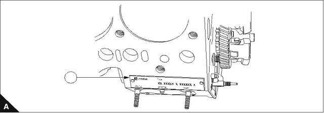
Engine I.D. location
The engine identification plate (A1) is located on the front right side of the engine, just above the fuel injection
pump.
It consists of the following:
Abbreviations and codes
Engine build list (parts list) numbering system
The standard engine parts list numbering code system is defined as follows:
Code
I
II
III
IV
V
Example
KE
30260
U
000001
D
Code I Engine Build Code
Engine
102 - 05
103 - 07
103 - 10
103 - 13
Build code
Engine
103 - 15
104 - 19
104 - 22
Build code
KN
KL
KE
KF
KR
KD
KH
Code II Engine parts list
Parts list increases numerically for both OEMS and distributors.
Code III Country of manufacture
Code
Country of manufacture
Made in Japan
J
U
Made in U.K.
Code IV Engine serial number
Individual engine serial number commencing with 000001 increasing numerically.
Code V Year of Manufacture
Code
Year
Code
Year
Code
Year
Code
Year
Code
Year
01/01/99
31/03/99
M
1985
T
1989
Y
1994
E
J
2002
01/04/99
31/12/99
N
1986
U
1990
A
1995
F
K
L
2003
2004
O
P
not used
1987
V
W
X
1991
1992
1993
B
C
D
1996
1997
1998
G
H
I
2000
2001
Q/S
1988
not used‘
1
Workshop Manual, TPD 1377E, issue 4
7
This document has been printed from SPI². Not for Resale
![]()
![]()
![]()


1
100 Series
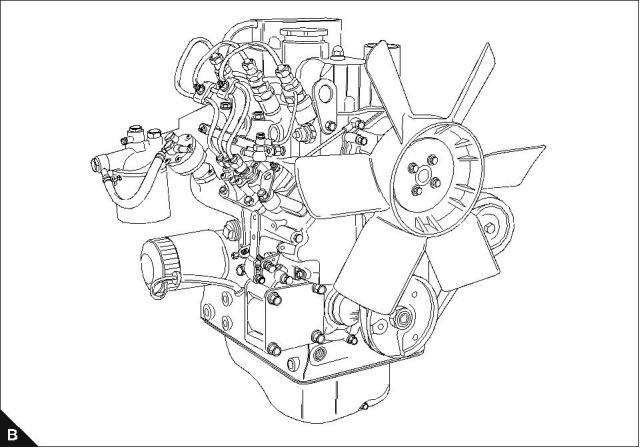
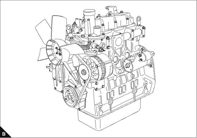
Engine views - 3 cylinder front and rear
8
Workshop Manual, TPD 1377E, issue 4
This document has been printed from SPI². Not for Resale
![]()
![]()

1
100 Series
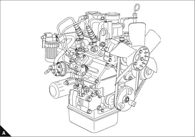
Engine views - 2 cylinder front and 4 cylinder front
Workshop Manual, TPD 1377E, issue 4
9
This document has been printed from SPI². Not for Resale
![]()
![]()
1
100 Series
Engine lift equipment
Special requirements
Torque Nm (lbf ft) kgf m
Lifting hook bolts (A1)
26 (19) 2,6
Maximum engine weights (dry) with flywheel and housing fitted
Engine model
Engine build code
Max engine weight
102-05
KN
103-07
KL
103-10
KD
103-13
KH
103-15
KE
104-19
KF
104-22
KR
79 kg
87 kg
111 kg
164 kg
176 kg
207 kg
220 kg
1
1
10
Workshop Manual, TPD 1377E, issue 4
This document has been printed from SPI². Not for Resale
![]()
![]()
![]()


1
100 Series
Viton seals
Some seals used in engines and in components fitted to engines are made of Viton.
Viton is used by many manufacturers and is a safe material under normal conditions of operation.
If Viton is burned, a product of this burnt material is an acid which is extremely dangerous. Never allow this
burnt material to come into contact with the skin or with the eyes.
If it is necessary to come into contact with components which have been burnt, ensure that the precautions
which follow are used:
Ensure that the components have cooled.
Use neoprene gloves and discard the gloves safely after use.
Wash the area with calcium hyd, roxide solution and then with clean water.
Disposal of components and gloves which are contaminated must be in accordance with local regulations.
Warning! If there is contamination of the skin or eyes, wash the affected area with a continuous supply of
clean water or with calcium hydroxide solution for 15-60 minutes. Obtain immediate medical attention.
Safety cautions, when an engine is cleaned
Care should be taken, when an engine is cleaned with the use of a high pressure hose.
Cautions:
Do not wash an engine while the engines runs or if it is hot. If cold cleaning fluids are applied to a hot engine,
certain components on the engine could be damaged.
Leave the engine to cool for at least one hour and disconnect the battery connections before cleaning.
Do not wash any part of the Fuel Injection Pump (FIP), glow plugs, electrical shut off solenoid (ESOS) or
electrical connectors.
Ensure that the alternator, starter motor and any other electrical components are shielded and not directly
cleaned by the high pressure cleaning system.
If these cautions are ignored, the engine or certain components of the engine could be damaged, fail to operate
and also make the manufacturer’s warranty invalid.
Engines that conform to Emissions Levels
Engines that are fitted with an emissions label on the timing case conform to stage 1 emissions legislation and,
for certain service procedures, additional information is included to ensure that the engine remains emissions
approved.
Workshop Manual, TPD 1377E, issue 4
11
This document has been printed from SPI². Not for Resale
![]()
![]()
![]()
![]()
![]()
![]()
![]()
![]()
![]()
![]()
1
100 Series
Compression test data
Tests have shown that many factors affect compression pressures. Battery, starter motor condition, ambient
conditions and the type of gauge used can give a wide variation of results for a given engine.
Pressure kPa (lbf/in²)
Engine model
Standard
To be repaired
<2450 (355.5)
<2450 (355.5)
102-05, 103-07, 103-10, 103-13
103-15, 104-19, 104-22
>2940 (426.6) @ 200 rev/min
>2940 (426.6) @ 250 rev/min
A compression test should only be used to compare between cylinders of an engine. If one or more cylinders
vary by more than 350 KPa (50 lbf/in²) then those cylinders may be faulty.
A compression test should not be the only method used to show the condition of an engine, but it should be
used together with other symptoms and tests.
How to do a compression test
Note: Before the compression test, ensure that the battery is in good condition and that it is fully charged. Also
ensure that the starter motor is in good condition.
1 To ensure that the engine cannot start, disconnect the engine stop solenoid or ensure the engine stop
control is in the ‘stop’ position.
2 Ensure that the valve tip clearances are set correctly.
3 Remove the atomisers.
4 Fit a suitable gauge into the atomiser hole of the cylinder to be tested.
5 Operate the starter motor and record the pressure indicated on the gauge.
6 Repeat for each cylinder.
12
Workshop Manual, TPD 1377E, issue 4
This document has been printed from SPI². Not for Resale
![]()
![]()


100 Series
2
Specifications
2
Basic engine data
Engine model
Engine build code
Number of cylinders
102-05
KN
103-07
103-10
KD
103-13
KH
103-15
KE
104-19
104-22
KR
KL
3
KF
4
2
3
3
3
4
Cylinder
arrangement and
cycle
Vertical in line, four stroke cycle
Direction of rotation
Induction system
Combustion system
Nominal bore
Clockwise, viewed from front
Naturally aspirated
IDI special swirl
67 mm
(2.6 in)
67 mm
(2.6 in)
75 mm
(2.9 in)
84 mm
(3.3 in)
84 mm
(3.3 in)
84 mm
(3.3 in)
84 mm
(3.3 in)
64 mm
(2.5 in)
64 mm
(2.5 in)
72 mm
(2.8 in)
80 mm
(3.1 in)
90 mm
(3.5 in)
90 mm
(3.5 in)
100 mm
(3.9 in)
Stroke
Compression ratio
24:1
24:1
23:1
22:1
22.5:1
22:1
22:1
0,451 ltrs.
(27.5 in³)
0,676 ltrs.
(41.2 in³)
0,954 ltrs.
(58.2 in³)
1,330 ltrs.
(81.1 in³)
1,496 ltrs.
(91.2 in³)
1,995 ltrs.
(121.7 in³)
2,216 ltrs.
(135.2 in³)
Cubic capacity
Firing order
1, 2
1, 2, 3
1, 2, 3
1, 2, 3
1, 2, 3
1, 3, 4, 2
1, 3, 4, 2
352-448
KPa
Oil pressure relief
Oil pressure switch
262-359 KPa
29,6 KPa
Valve tip clearance
(cold)
0,2 mm
(0.0078 in)
-Inlet
0,2 mm
(0.0078 in)
-Exhaust
Electrical system
Governor
12 volt
Mechanical all speed
Fuel injection
Cassette type fuel injection system
Workshop Manual, TPD 1377E, issue 4
13
This document has been printed from SPI². Not for Resale
![]()
![]()

2
100 Series
Thread Sealant
When setscrews or studs are fitted into holes which are tapped through the cylinder block, a suitable sealant
must be used to prevent leakage.
Micro encapsulated anaerobic sealant (M.E.A.S) fasteners have been introduced instead of jointing
compounds or other sealants when the fasteners are fitted in through holes into oil or coolant passages. The
identification of these fasteners, as supplied, is by a red, blue, or other colour sealant around the fastener
threads.
With M.E.A.S. sealed studs, the sealed end must be fitted into the cylinder head / cylinder block etc. Ensure
that the threaded holes have a 1,59 mm (0.0625 in) 45° chamfer, to ensure that when the new fasteners are
fitted the M.E.A.S. sealant is not removed. If the fasteners have to be removed and fitted again, the threads
must be cleaned and a suitable sealant used.
Note: New setscrews have sealant applied by the manufacturer to the first 13,0 mm (0.50 in) of the threads.
If the setscrews are to be used again, clean the old sealant from the male and female threads and apply new
sealant, (Powerpart Threadlock and Nutlock) to the setscrews.
Recommended torque tensions
Most of the torques on the engine are standard. Torques specific to individual operations are listed in the
relevant operation. The standard torques listed in the tables below can be used when a specific torque is not
necessary.
Note: The torques below apply to components lubricated lightly with clean engine oil before they are fitted.
Standard torques for setscrews, studs and nuts
Coarse Screw Thread
Fine Screw Thread
Thread
size
Bolt
Strength
Pitch
(mm)
Torque
(Nm)
Torque
(lbf ft)
Torque
(kgf m)
Pitch
(mm)
Torque
(Nm)
Torque
(lbf ft)
Torque
(kgf m)
8.8
11T
3
4
2
3
0,3
0,4
M4
M5
0,7
0,8
8.8
11T
6
8
4
6
0,6
0,8
8.8
11T
10
14
7
10
1,0
1,4
M6
1,0
8.8
11T
26
32
19
24
2,7
3,3
30
35
22
26
3,0
3,6
M8
1,25
1,5
1,0
1,25
1,25
1,5
8.8
11T
50
62
37
46
5,1
6,3
56
66
41
49
5,7
6,7
M10
M12
M14
M16
8.8
11T
75
104
55
77
7,6
10,6
84
113
62
83
8,6
11,5
1,75
2,0
8.8
11T
118
157
87
116
12,0
16,0
132
167
97
123
13,5
17,0
8.8
11T
167
230
123
170
17,0
23,4
175
245
129
181
17,8
20,5
2,0
1,5
Examples of applicable material
Bolt
Example
Strength
8.8
S45C
11T
SCM435
14
Workshop Manual, TPD 1377E, issue 4
This document has been printed from SPI². Not for Resale
![]()
![]()


2
100 Series
Data and dimensions
Note: The information in this Workshop Manual is given as a guide for personnel engaged on engine
overhauls. The dimensions which are shown are those which are mainly used in production.
Injection timing
Engine build list
Engine type
102-05
Injection timing
25.5° ± 1°
KN30305, KN30306
KN30308, KN30309
KN30304, KN30327
102-05
27.5° ± 1°
KL30317, KL30318
KL30319, KL30320
KL30323, KL30324
KL30325, KL30326
103-07
17.0° ± 1°
KD30238, KD30239
KD30240
103-10
103-10
103-10
103-13
103-15
103-15
104-19
104-22
104-22
23.0° ± 1°
22.5° ± 1°
18.5° ± 1°
22.5° ± 1°
22.5° ± 1°
16.0° ± 1°
21.5° ± 1°
16.0° ± 1°
20.0° ± 1°
KD30241, KD30242
KD30247, KD30248
KD30245, KD30246
KH30255, KH30256
KH30273
KE30260, KE30261
KE30274
KE30262, KE30263
KF30265, KF30266
KF30276
KR30334, KR30335
KR30331, KR30332
KR30333
Note: OEM build lists can be found on the relevant service bulletin. If the timing is incorrect refer to "Fuel
injection pump timing" on page 85.
Workshop Manual, TPD 1377E, issue 4
15
This document has been printed from SPI². Not for Resale
![]()
![]()

2
100 Series
Cylinder bore dimensions
Bore dimension mm (in)
Engine model/Block specification
Standard
Service limit
102-05, 103-07
New Block
67,000 - 67,019 (2.63780 - 2.63854)
67,500 - 67,519 (2.65750 - 2.65822)
68,000 - 68,019 (2.67720 - 2.67791)
67,2 (2.646)
67,7 (2.666)
68,2 (2.685)
1st oversize bore 0,5 mm (0.2 in)
2nd oversize bore 1,0 mm (0.4 in)
103-10
New Block
75,000 - 75,019 (2.95280 - 2.95350)
75,500 - 75,519 (2.97244 - 2.97318)
76,000 - 76,019 (2.99212 - 2.99287)
75,2 (2.961)
75,7 (2.981)
76,2 (2.999)
1st oversize bore 0,5 mm (0.2 in)
2nd oversize bore 1,0 mm (0.4 in)
103-13, 103-15, 104-19, 104-22
New Block
84,000 - 84,019 (3.30710 - 3.30783)
84,500 - 84,519 (3.32677 - 3.32751)
85,000 - 85,019 (3.34650 - 3.34719)
84,2 (3.315)
84,7 (3.335)
85,2 (3.354)
1st oversize bore 0,5 mm (0.2 in)
2nd oversize bore 1,0 mm (0.4 in)
Caution: When service limits are exceeded following a second oversize bore operation, the block must be
renewed.
16
Workshop Manual, TPD 1377E, issue 4
This document has been printed from SPI². Not for Resale
![]()
![]()

![]()
![]()
![]()
2
100 Series
Piston and piston ring dimensions
Piston
If the outer surface of the piston is excessively damaged (cracked, scored, or it shows signs of being burnt etc.)
it must be renewed.
Piston skirt
1 Check the larger diameter of the piston skirt (10 mm from bottom) with reference to the following tables.
102-05, 103-07, 103-10, 103-13
Diameter mm (in)
Piston
size
102-05, 103-07
103-10
103-13
66,9375 - 66,9525
(2.6353- 2.6359)
74,9325 - 74,9475
(2.950100 - 2.950690)
83,948 - 83,963
(3.30503 - 3.30562)
Standard
0,5 mm
oversize
67,4375 - 67,4525
(2.6550 - 2.6556)
75,4325 - 75,4475
(2.969780 - 2.970370)
84,448 - 84,463
(3.32472 - 3.32531)
1,0 mm
oversize
75,9325 - 75,9475
(2.989463 - 2.990060)
84,948 - 84,963
(3.34440 - 3.34499)
Not applicable
103-15, 104-19, 104-22
Diameter mm (in)
Piston
size
103-15, 104-19
104-22
83,948 - 83,963
(3.30503 - 3.30567)
83,948 - 83,963
(3.30503 - 3.30562)
Standard
0,5 mm
84,448 - 84,463
84,448 - 84,463
oversize
(3.32472 - 3.32531)
(3.32472 - 3.32531)
1,0 mm
84,948 - 84,963
84,948 - 84,963
oversize
(3.34440 - 3.34499)
(3.34440 - 3.34499)
2 Check inside diameter (thrust direction) of the cylinder.
Diameter mm (in)
Engine model
Standard
Service limit
66,7 (2.626)
74,7 (2.941)
83,7 (3.295)
102-05, 103-07
66,9375 - 66,9525 (2.6353 - 2.6359)
74,9325 - 74,9475 (2.950100 - 2.950690)
83,948 - 83,963 (3.30503 - 3.30562)
103-10
103-13, 103-15, 104-19, 104-22
3 Calculate the clearance between the cylinder and piston. If this clearance is more than standard, or the
piston diameter is less than the service limit, renew the piston.
Clearance mm (in)
Engine model
Standard
Service limit
0,25 (0.010)
0,25 (0.010)
0,25 (0.010)
102-05, 103-07
0,048 - 0,082 (0.00189 - 0.00323)
0,0525 - 0,0865 (0.002070 - 0.003406)
0,038 - 0,072 (0.00150 - 0.00283)
103-10
103-13, 103-15, 104-19, 104-22
Oversized piston
When the cylinder is oversized, ensure that the correct oversized piston and piston ring set is used.
Note: Ring sets are available for all pistons listed above.
Workshop Manual, TPD 1377E, issue 4
17
This document has been printed from SPI². Not for Resale
![]()
![]()


2
100 Series
Gudgeon pin
1 Check the outside diameter of the gudgeon pin. If it is less than the service limit, renew the pin.
Diameter mm (in)
Engine model
Standard
Service limit
102-05, 103-07
103-10
18,998 - 19,002 (0.74795 - 0.74811)
20,998 - 21,002 (0.82669 - 0.82685)
24,996 - 25,00 (0.98410 - 0.98425)
27,996 - 28,000 (1.10220 - 1.10240)
27,996 - 28,000 (1.10220 - 1.10240)
27,996 - 28,000 (1.10220 - 1.10240)
18,98 (0.7472)
20,98 (0.8259)
24,98 (0.9835)
27,98 (1.1016)
27,98 (1.1016)
27,98 (1.1016)
103-13
103-15
104-19
104-22
2 Check the clearance between gudgeon pin hole and gudgeon pin. Check the inside diameter of the gudgeon
pin hole and the outside diameter of the gudgeon pin, and calculate the clearance between them. If the
clearance is more than the service limit, renew the piston and gudgeon pin.
Clearance mm (in)
Engine model
Standard
Service limit
0,02 (0.0008)
0,02 (0.0008)
102-05, 103-07, 103-10
-0,004 to +0,004 (-0.00016 to +0.00016)
-0,001 to +0,007 (-0.00040 to +0.00030)
103-13, 103-15, 104-19, 104-22
18
Workshop Manual, TPD 1377E, issue 4
This document has been printed from SPI². Not for Resale
![]()
![]()


2
100 Series
Crankshaft deflection
1 Support the crankshaft with a V-block.
2 Position a dial gauge on the crankshaft centre journal, and turn the crankshaft gradually by one full turn.
3 If the gauge reading is more than the service limit correction or replacement of the crankshaft is needed.
Deflection mm (in)
Standard
Service limit
0,03 or less (0.011)
0,06 (0.0023)
4 If measured diameter is less than the service limit, correct by grinding and use undersized bearings and bush.
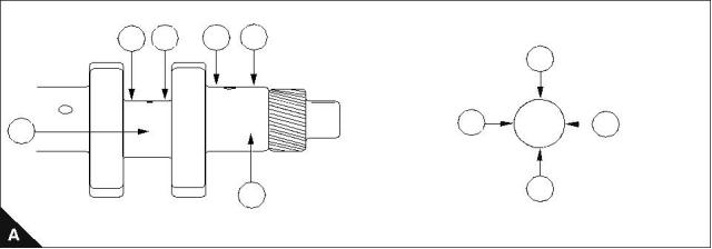
Crankshaft inspection
1 Check the oil seal contact face for damage or wear.
2 Check oil holes for blockage.
3 Check crankshaft journal (A4) and pin (A3) for stepped wear. Take measurements of diameters (A5-A5) and
(A6-A6) at positions (A1) and (A2). If the maximum difference between the measurements (stepped wear) is
more than the service limit of 0,05 mm (0.0019 in) then correction is required.
Grinding specification
When grinding the crankshaft, work with the following specifications:
Radius at pin/journal (B1):
Finish precision (B2):
3 mm ± 0,2 mm (0.118 in ± 0.0078 in).
1.6Z
Radius around oil hole (B3):
2 mm (0.0787 in) maximum/5 mm (0.196 in) minimum.
Note: Use No. 400 emery cloth for final polishing.
1
2
1
2
5
5
6
6
3
4
1
2
3
Workshop Manual, TPD 1377E, issue 4
19
This document has been printed from SPI². Not for Resale
![]()
![]()

![]()

2
100 Series
Crankshaft journal diameters
Diameter mm (in)
Journal
No.
Engine model/Journal type
Standard
Service limit
102-05
1
2
1
2
1
2
42,964 - 42,975 (1.69150 - 1.69193)
45,948 - 45,959 (1.80897 - 1.80941)
42,714 - 42,725 (1.68165 - 1.68210)
45,698 - 45,709 (1.79913 - 1.79960)
42,464 - 42,475 (1.67181 - 1.67224)
45,448 - 45,459 (1.78930 - 1.78972)
42,90 (1.689)
45,90 (1.807)
42,65 (1.679)
45,65 (1.797)
42,40 (1.669) (1)
45,40 (1.787) (1)
Standard
Undersize 0,25 mm (0.01 in)
Undersize 0,50 mm (0.02 in)
103-07
1, 2
3
42,964 - 42,975 (1.69150 - 1.69193)
45,948 - 45,959 (1.80897 - 1.80941)
42,714 - 42,725 (1.68165 - 1.68210)
45,698 - 45,709 (1.79913 - 1.79960)
42,464 - 42,475 (1.67181 - 1.67224)
45,448 - 45,459 (1.78930 - 1.78972)
42,90 (1.689)
45,90 (1.807)
42,65 (1.679)
45,65 (1.797)
42,40 (1.669) (1)
45,40 (1.787) (1)
Standard
1, 2
3
Undersize 0,25 mm (0.01 in)
Undersize 0,50 mm (0.02 in)
1, 2
3
103-10
Standard
1, 2, 3
1, 2, 3
1, 2, 3
45,964 - 45,975 (1.80960 - 1.81004)
45,714 - 45,725 (1.79980 - 1.80020)
45,464 - 45,475 (1.78992 - 1.79035)
45,90 (1.807)
45,65 (1.797)
Undersize 0,25 mm (0.01 in)
Undersize 0,50 mm (0.02 in)
103-13
45,40 (1.787) (1)
Standard
1, 2, 3
1, 2, 3
1, 2, 3
57,957 - 57,970 (2.28177 - 2.28228)
57,707 - 57,720 (2.27192 - 2.27244)
57,457 - 57,470 (2.26210 - 2.26260)
57,9 (2.280)
57,6 (2.268)
Undersize 0,25 mm (0.01 in)
Undersize 0,50 mm (0.02 in)
103-15
57,4 (2.260) (1)
Standard
1, 2, 3
1, 2, 3
1, 2, 3
67,957 - 67,970 (2.67550 - 2.67597)
67,707 - 67,720 (2.66563 - 2.66614)
67,457 - 67,470 (2.65579 - 2.65630)
67,90 (2.6732)
67,65 (2.6634)
67,40 (2.6535) (1)
Undersize 0,25 mm (0.01 in)
Undersize 0,50 mm (0.02 in)
104-19, 104-22
Standard
1, 2, 3, 4
1, 2, 3, 4
1, 2, 3, 4
67,957 - 67,970 (2.67550 - 2.67597)
67,707 - 67,720 (2.66563 - 2.66614)
67,457 - 67,470 (2.65579 - 2.65630)
67,90 (2.6732)
67,65 (2.6634)
67,40 (2.6535) (1)
Undersize 0,25 mm (0.01 in)
Undersize 0,50 mm (0.02 in)
(1) If the diameter is less than this value, the crankshaft must be renewed.
20
Workshop Manual, TPD 1377E, issue 4
This document has been printed from SPI². Not for Resale
![]()
![]()

2
100 Series
Crankshaft pin diameters
Diameter mm (in)
Engine model/Pin type
Standard
Service limit
102-05, 103-07
Standard
34,964 - 34,975 (1.37653 - 1.37697)
34,714 - 34,725 (1.36669 - 1.36712)
34,464 - 34,475 (1.35685 - 1.35728)
34,90 (1.374)
34,65 (1.364)
Undersize 0,25 mm (0.01 in)
Undersize 0,50 mm (0.02 in)
103-10
34,40 (1.354) (1)
Standard
38,964 - 38,975 (1.53401 - 1.53445)
38,714 - 38,725 (1.52417 - 1.52460)
38,464 - 38,475 (1.51433 - 1.51476)
38,90 (1.531)
38,65 (1.5216)
Undersize 0,25 mm (0.01 in)
Undersize 0,50 mm (0.02 in)
103-13
38,40 (1.5118) (1)
Standard
43,964 - 43,975 (1.73090 - 1.73130)
43,714 - 43,725 (1.72102 - 1.72145)
43,464 - 43,475 (1.71120 - 1.71161)
43,90 (1.728)
43,65 (1.719)
Undersize 0,25 mm (0.01 in)
Undersize 0,50 mm (0.02 in )
103-15, 104-19, 104-22
Standard
43,40 (1.709) (1)
51,964 - 51,975 (2.04582 - 2.04626)
51,714 - 51,725 (2.03598 - 2.03641)
51,464 - 51,475 (2.02614 - 2.02660)
51,90 (2.0433)
51,65 (2.0335)
51,40 (2.0236) (1)
Undersize 0,25 mm (0.01 in)
Undersize 0,50 mm (0.02 in)
(1) If the diameter is less than this value, the crankshaft must be renewed.
Workshop Manual, TPD 1377E, issue 4
21
This document has been printed from SPI². Not for Resale
![]()
![]()

2
100 Series
Bearing holder
Centre bearing
1 Remove the bearing holder and check it for stepped wear and other damage. If it is excessively damaged
renew.
2 Using the Plastigauge ®, measure the oil clearance between the crankshaft centre journal and the bearing.
If the oil clearance is more than the service limit, renew the bearing or grind the crankshaft centre journal and
use an undersize bearing.
Clearance mm (in)
Engine model/Journal No.
Standard
Service limit
102-05
No. 1
0,035 - 0,088 (0.00140 - 0.00350)
0,039 - 0,092 (0.00154 - 0.00362)
0,20 (0.0078)
0,20 (0.0078)
No. 2
103-07
No. 1, 2
0,035 - 0,088 (0.00140 - 0.00350)
0,039 - 0,092 (0.00154 - 0.00362)
0,20 (0.0078)
0,20 (0.0078)
No. 3
103-10
No. 1, 2, 3
103-13, 103-15
No. 1, 2, 3
104-19, 104-22
No. 1, 2, 3, 4
0,039 - 0,092 (0.00154 - 0.00362)
0,044 - 0,102 (0.00173 - 0.00401)
0,044 - 0,102 (0.00173 - 0.00401)
0,20 (0.0078)
0,20 (0.0078)
0,20 (0.0078)
22
Workshop Manual, TPD 1377E, issue 4
This document has been printed from SPI². Not for Resale
![]()
![]()

2
100 Series
Undersize bearing shell chart
Journal
No.
Crankshaft centre
journal diameter mm (in)
Engine model/Bearing size
102-05
1
2
1
2
1
2
42,964 - 42,975 (1.69150 - 1.69193)
45,948 - 45,959 (1.80897 - 1.80941)
42,714 - 42,725 (1.68165 - 1.68210)
45,698 - 45,709 (1.79913 - 1.79956)
42,464 - 42,475 (1.67181 - 1.67224)
45,448 - 45,459 (1.78930 - 1.78972)
Standard
Undersize 0,25 mm (0.01 in)
Undersize 0,50 mm (0.02 in)
103-07
1, 2
3
42,964 - 42,975 (1.69150 - 1.69193)
45,948 - 45,959 (1.80897 - 1.80941)
42,714 - 42,725 (1.68165 - 1.68210)
45,698 - 45,709 (1.79913 - 1.79956)
42,464 - 42,475 (1.67181 - 1.67224)
45,448 - 45,459 (1.78930 - 1.78972)
Standard
1, 2
3
Undersize 0,25 mm (0.01 in)
Undersize 0,50 mm (0.02 in)
1, 2
3
103-10
Standard
1, 2, 3
1, 2, 3
1, 2, 3
45,964 - 45,975 (1.80960 - 1.81004)
45,714 - 45,725 (1.79976 - 1.80019)
45,464 - 45,475 (1.78992 - 1.79035)
Undersize 0,25 mm (0.01 in)
Undersize 0,50 mm (0.02 in)
103-13
Standard
1, 2, 3
1, 2, 3
1, 2, 3
57,957 - 57,970 (2.28177 - 2.28228)
57,707 - 57,720 (2.27192 - 2.27244)
57,457 - 57,470 (2.26210 - 2.26260)
Undersize 0,25 mm (0.01 in)
Undersize 0,50 mm (0.02 in)
103-15
Standard
1, 2, 3
1, 2, 3
1, 2, 3
67,957 - 67,970 (2.67550 - 2.67597)
67,707 - 67,720 (2.66563 - 2.66614)
67,457 - 67,470 (2.65579 - 2.65630)
Undersize 0,25 mm (0.01 in)
Undersize 0,50 mm (0.02 in)
104-19, 104-22
Standard
1, 2, 3, 4
1, 2, 3, 4
1, 2, 3, 4
67,957 - 67,970 (2.67550 - 2.67597)
67,707 - 67,720 (2.66563 - 2.66614)
67,457 - 67,470 (2.65579 - 2.65630)
Undersize 0,25 mm (0.01 in)
Undersize 0,50 mm (0.02 in)
Workshop Manual, TPD 1377E, issue 4
23
This document has been printed from SPI². Not for Resale
![]()
![]()

2
100 Series
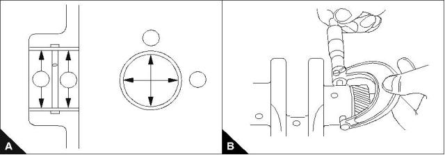
Crankshaft bearing bush
1 Check the bearing (bush) for damage or poor contact. If found to be defective, renew.
2 Using a cylinder gauge and micrometer, measure the clearance between the bearing (bush) and the
crankshaft journal (B).
3 Measure inside diameters at positions (A1) and (A2). At each position measure in both directions (A3) and
(A4) as shown. The oil clearance can be obtained by subtracting this value from the maximum crankshaft
journal diameter.
Clearance mm (in)
Engine model
Standard
Service limit
0,20 (0.0078)
0,20 (0.0078)
0,20 (0.0078)
102-05, 103-07
0,035 - 0,102 (0.00140 - 0.00401)
0,039 - 0,106 (0.00154 - 0.00420)
0,044 - 0,116 (0.00173 - 0.00456)
103-10
103-13, 103-15, 104-19, 104-22
4 If the oil clearance exceeds the service limit renew the bearing (bush), or grind the crankshaft journal to the
required specifications. In this case use an undersize bearing (bush).
5 To renew the crankshaft journal (bush), use a press to install.
Crankshaft journal
Engine model/Bush size
O.D. finished size mm (in)
102-05, 103-07
Standard
42,964 - 42,975 (1.69150 - 1.69193)
42,714 - 45,725 (1.68165 - 1.68210)
42,464 - 42,475 (1.67181 - 1.67224)
Undersize 0,25 mm (0.01 in)
Undersize 0,50 mm (0.02 in)
103-10
Standard
45,964 - 45,975 (1.80960 - 1.81004)
45,714 - 45,725 (1.79980 - 1.80020)
45,464 - 45,475 (1.78992 - 1.79035)
Undersize 0,25 mm (0.01 in)
Undersize 0,50 mm (0.02 in)
103-13
Standard
57,957 - 57,970 (2.28177 - 2.28228)
57,707 - 57,720 (2.27192 - 2.27244)
57,457 - 57,470 (2.26210 - 2.26260)
Undersize 0,25 mm (0.01 in)
Undersize 0,50 mm (0.02 in)
103-15, 104-19, 104-22
Standard
67,957 - 67,970 (2.67550 - 2.67597)
67,707 - 67,720 (2.66563 - 2.66614)
67,457 - 67,470 (2.65579 - 2.65630)
Undersize 0,25 mm (0.01 in)
Undersize 0,50 mm (0.02 in)
3
1
2
4
24
Workshop Manual, TPD 1377E, issue 4
This document has been printed from SPI². Not for Resale
![]()
![]()


100 Series
3
Cylinder head assembly
3
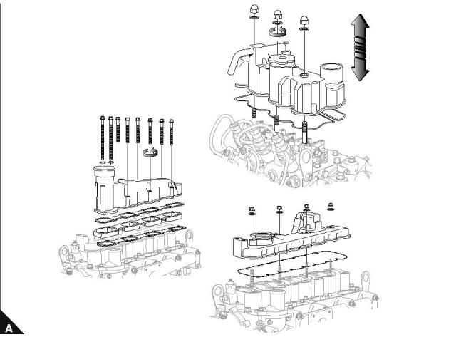
Rocker cover and inlet manifold
To remove and to fit
Operation 3-1
Special requirements
Torque Nm (lbf ft) kgf m
102-05, 103-07, 103-10
103-13, 103-15
11 (8) 1,1
10 (7) 1,0
14 (10) 1,4
104-19, 104-22
Note: Inspect the joint, renew if necessary.
102-05
103-07
103-10
103-13
103-15
104-19
104-20
103-13
103-15
104-19
104-20
Workshop Manual, TPD 1377E, issue 4
25
This document has been printed from SPI². Not for Resale
![]()
![]()
![]()
![]()

3
100 Series
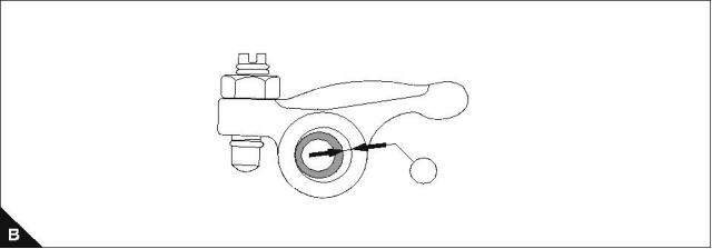
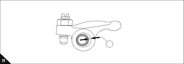
Rocker assembly
To remove and to fit
Operation 3-2
Special requirements
Torque Nm (lbf ft) kgf m
102-05, 103-07, 103-10
103-13, 103-15
104-19, 104-22
Bolts (A2)
23 (17) 2,3
23 (17) 2,3
33 (24) 3,3
6 (4) 0,6
Note: Ensure that the valve stem caps (A1) remain on the valve stems.
102-05
103-07
103-10
1
2
103-13
103-15
104-19
104-22
26
Workshop Manual, TPD 1377E, issue 4
This document has been printed from SPI². Not for Resale
![]()
![]()
![]()
![]()


3
100 Series
Rocker shaft (102-05, 103-07, 103-10)
To dismantle, to inspect and to assemble
Operation 3-3
Special requirements
Diameter (A) mm (in)
Clearance (B1) mm (in)
Standard
Service limit
Standard
Service limit
11,65 - 11,67 (0.4587 - 0.4595)
11,57 (0.4555) max
0,032 - 0,068 (0.00126 - 0.00268)
0,2 (0.008) max
1
Workshop Manual, TPD 1377E, issue 4
27
This document has been printed from SPI². Not for Resale
![]()
![]()
![]()
![]()


3
100 Series
Rocker shaft (103-13, 103-15, 104-19, 104-22)
To dismantle, to inspect and to assemble
Special requirements
Operation 3-4
Diameter (A) mm (in)
Engine model
Standard
Service limit
103-13, 103-15
104-19, 104-22
11,65 - 11,67 (0.4587 - 0.4595)
14,95 - 14,97 (0.5886 - 0.5894)
11,57 (0.4555) max
14,87 (0.5854) max
Clearance (B1) mm (in)
Engine model
Standard
Service limit
0,2 (0.008) max
0,2 (0.008) max
103-13, 103-15
104-19, 104-22
0,032 - 0,068 (0.00126 - 0.00268)
0,030 - 0,093 (0.00120 - 0.00366)
Note: Be aware of the position of the shaft location recess (A1).
1
1
28
Workshop Manual, TPD 1377E, issue 4
This document has been printed from SPI². Not for Resale
![]()
![]()
![]()
![]()


3
100 Series
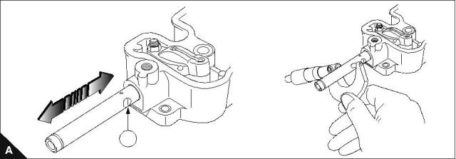
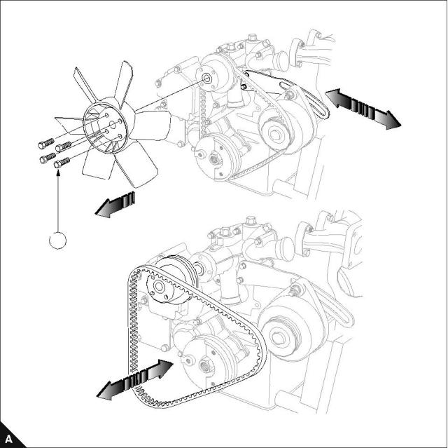
Fan and mounting
To remove
Operation 3-5
Special requirements
Tension Nm (lbf ft) kgf m
Bolts (A1)
11 (8) 1,1
To fit and tension the fan belt refer to Operation 12-1.
1
Workshop Manual, TPD 1377E, issue 4
29
This document has been printed from SPI². Not for Resale
![]()
![]()
![]()
![]()
![]()
3
100 Series
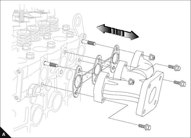
Exhaust manifold and gasket
To remove and to fit
Operation 3-6
30
Workshop Manual, TPD 1377E, issue 4
This document has been printed from SPI². Not for Resale
![]()
![]()
![]()
![]()
3
100 Series
Fuel injection pipes / fuel return pipes
To remove and to fit
Operation 3-7
Special requirements
Torque Nm (lbf ft) kgf m
102-05, 103-07, 103-10
22 (16) 2,2
103-13, 103-15, 104-19, 104-22
20 (15) 2,0
Notes:
Be aware of holes in washers (A1).
For emissions approved engines. It is essential that the fuel adjustment screw is not altered from the
original setting.
For emissions approved engines. The maximum No Load Speed must be checked after assembly.
1
Workshop Manual, TPD 1377E, issue 4
31
This document has been printed from SPI². Not for Resale
![]()
![]()
![]()
![]()
![]()
![]()
![]()


3
100 Series
Oil pipes
To remove and to fit
Operation 3-8
Special requirements
Torque Nm (lbf ft) kgf m
102-05, 103-07, 103-10
11 (8) 1,1
12 (9) 1,2
103-13, 103-15, 104-19, 104-22
Notes:
Be aware of the oil restriction in the banjo bolts (A1).
The diagram below shows a typical arrangement only.
1
32
Workshop Manual, TPD 1377E, issue 4
This document has been printed from SPI². Not for Resale
![]()
![]()
![]()
![]()
![]()
![]()


3
100 Series
Atomisers
To remove and to fit
Operation 3-9
Special requirements
Torque Nm (lbf ft) kgf m
Test Pressure kgf/cm² (lbf/in²) ats
102-05, 103-07
64 (47) 6,5
81 (60) 8,2
64 (47) 6,5
102-05, 103-07
120 (1707) 116
120 (1707) 116
150 (2133) 145
103-10
103-10
103-13, 103-15, 104-19, 104-22
103-13, 103-15, 104-19, 104-22
Cautions:
Deep sockets should always be used during this procedure.
Connections should be blanked off until assembly.
Notes:
Item (A1) is used on 103-10 engines only.
For emissions approved engines. It is essential that the fuel adjustment screw is not altered from the
original setting.
For emissions approved engines. The maximum No Load Speed must be checked after assembly.
103-13
103-15
104-19
104-22
102-05
103-07
103-10
1
Workshop Manual, TPD 1377E, issue 4
33
This document has been printed from SPI². Not for Resale
![]()
![]()
![]()
![]()
![]()
![]()
![]()
![]()
![]()


3
100 Series
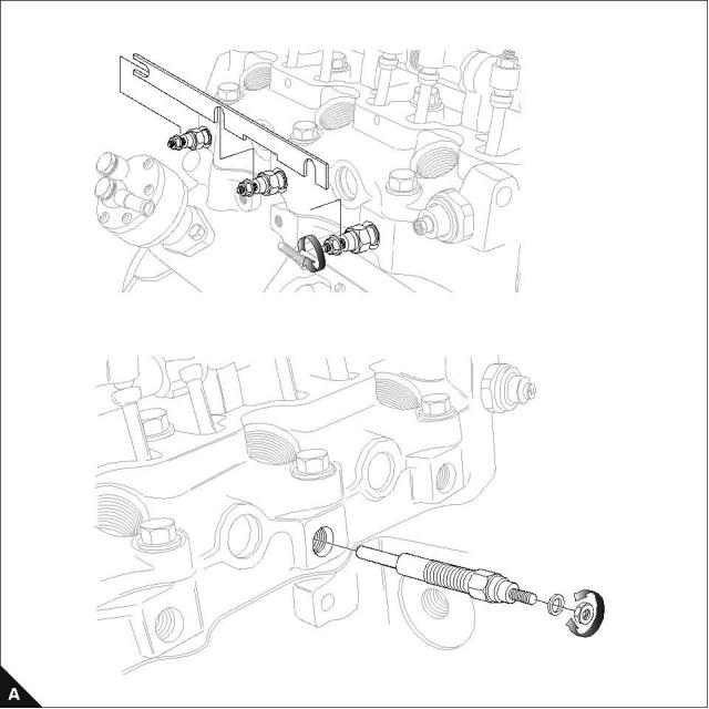
Busbar / glowplugs
To remove and to fit
Operation 3-10
Special requirements
Torque Nm (lbf ft) kgf m
Glowplugs
Contacts
17 (12) 1,7
17 (12) 1,7
Note: The diagram below shows a typical arrangement only.
34
Workshop Manual, TPD 1377E, issue 4
This document has been printed from SPI². Not for Resale
![]()
![]()
![]()
![]()

3
100 Series
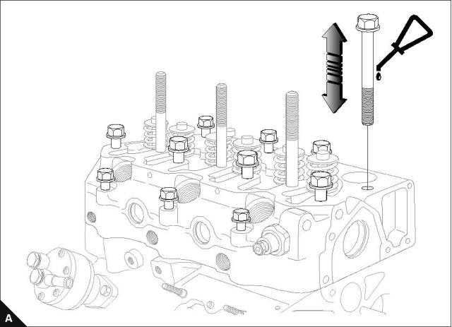
Head bolts
To remove and to fit
Operation 3-11
For recommended torques and tightening sequences refer to Operation 3-14.
Notes:
Lubricate bolts with engine lubricating oil.
For emissions approved engines. It is essential that the fuel adjustment screw is not altered from the
original setting.
For emissions approved engines. The maximum No Load Speed must be checked after assembly.
Workshop Manual, TPD 1377E, issue 4
35
This document has been printed from SPI². Not for Resale
![]()
![]()
![]()
![]()
![]()
![]()
![]()
3
100 Series
Cylinder head gasket
To remove and to fit
Operation 3-12
Align gasket on dowels, gasket must only be assembled with markings (A1) facing up.
Notes:
Always fit dry.
For emissions approved engines. If the cylinder block, crankshaft, connecting rods or pistons are changed,
the piston height must be checked and the correct thickness gasket used, refer to operation 3-13.
1
36
Workshop Manual, TPD 1377E, issue 4
This document has been printed from SPI². Not for Resale
![]()
![]()
![]()
![]()
![]()
![]()

3
100 Series
To select the correct thickness of cylinder head gasket
Operation 3-13
Caution: If the correct piston height above or below the cylinder block is not obtained, damage to the engine
can occur. The difference between the highest and the lowest piston height must not exceed 0.1 mm.
1 Put the piston height tool (A) on the face of the cylinder block and rotate the gauge dial to the zero position.
2 Rotate the crankshaft until the piston crown is approximately at top dead centre (TDC).
3 Carefully put the tool over the top of the piston with the plunger of the gauge in contact with the piston above
the axis of the gudgeon pin.
4 Rotate the crankshaft to ensure that the piston is at the highest position and make a note of the gauge
indication.
Notes:
If the cylinder block, crankshaft, connecting rods or pistons are changed the piston height will have to be
checked and the correct thickness gasket used.
If the original piston is used, ensure that it is assembled to the correct connecting rod and is used in the
original cylinder.
Cylinder head gasket selection
Engine
Protrusion above cylinder block top face
0,45 to 0,55 mm
Gasket thickness
1,1 mm
0,56 to 0,65 mm
1,2 mm
0,66 to 0,75 mm
1,3 mm
103-13
103-15
0,60 to 0,70 mm
1,3 mm
0,71 to 0,80 mm
1,4 mm
0,50 to 0,60 mm
1,2 mm
104-19
Engine
102-05
0,61 to 0,70 mm
1,3 mm
Protrusion below cylinder block top face
-0,30 to -0,15 mm
Gasket thickness
0,5 mm
-0,16 to +0,05 mm
0,6 mm
-0,40 to -0,25 mm
0,4 mm
103-07
104-22
-0,26 to -0,15 mm
0,5 mm
-0,45 to -0,30 mm
0,4 mm
-0,29 to -0,20 mm
0,5 mm
A
H1044
Workshop Manual, TPD 1377E, issue 4
37
This document has been printed from SPI². Not for Resale
![]()
![]()
![]()
![]()
![]()
![]()


3
100 Series
Head bolts - all variants
Tightening sequence
Operation 3-14
Special requirements
Torque Nm (lbf ft) kgf m
102-05, 103-07
103-10
37 (27) 3,7
103-13, 103-15, 104-19, 104-22
100 (74) 10,2
51 (38) 5,2
Note: All torques should be rechecked after tightening. Item (C1) is present on 104-19 models only.
102-05
3
1
2
5
9
7
8
10
4
6
103-07
103-10
103-13
103-15
5
11
9
13
1
3
7
8
6
4
2
14
4
10
5
12
104-19
104-22
12
13
8
1
9
16
15
17
18
1
7
2
10
11
3
6
14
38
Workshop Manual, TPD 1377E, issue 4
This document has been printed from SPI². Not for Resale
![]()
![]()
![]()
![]()


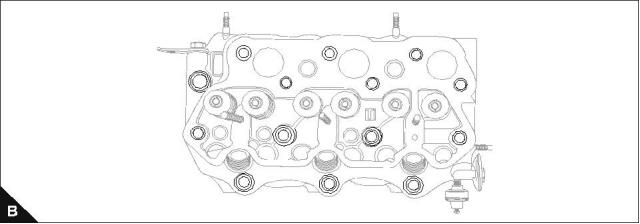
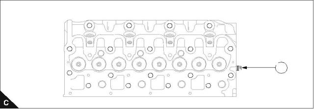
3
100 Series
Valve and valve springs
To remove and to fit
Operation 3-15
Special requirements
Special tools
Description
Valve spring remover
Part number
Description
Part number
21825663
21825622
Stem seal replacer - 103-10, 103-13,
103-15, 104-19, 104-22
21825623
Stem seal replacer - 102-05, 103-07
Caution: Always wear safety glasses.
Inlet and exhaust seals are different on 103-10 and above:
Inlet: Silver garter spring.
Exhaust: Black garter spring with small "EX" inscribed on garter.
Workshop Manual, TPD 1377E, issue 4
39
This document has been printed from SPI². Not for Resale