强鹿JOHN DEERE柴油机配件、发动机配件、发电机组:
RE507980、RE531703、RE24619、RE187966、RE205726、RE507264、RE504836、RE509036、RE533910、RE532952、RE530107、RE508971、RE523502、RE518520、RE68345、RE53307、RE62240、RE533095、RE502513、RE38009、R30402、RE521538、RE521540、RE62240、P524837、RE60021、RE507236、RE59588、RE549153、RE530870、SE501610、SE501609、RE70960
麦克福斯约翰迪尔发动机零配件
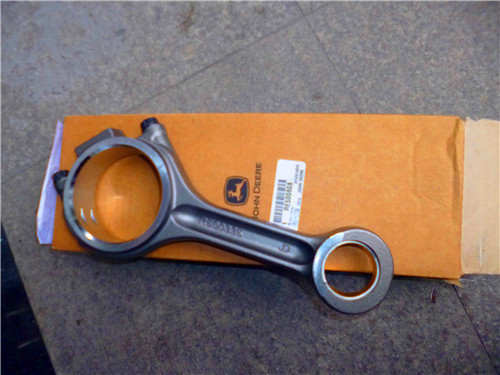
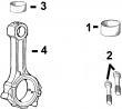
约翰迪尔 6081 低压缩活塞
|
型号 |
数量 |
描述 |
|
TAR49025 |
1 |
约翰迪尔(John Deere) 强鹿6081发动机后油封/ WITH WEAR SLEEVE |
|
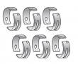
TR116081 |
6 |
约翰迪尔(John Deere) 强鹿6081发动机连杆瓦(标准 |
|
TR501035 |
12 |
约翰迪尔(John Deere) 强鹿6081发动机连杆螺钉 |
|
TR74008 |
6 |
约翰迪尔(John Deere) 强鹿6081发动机连杆衬套 |
|
TR87561 |
4 |
约翰迪尔(John Deere) 强鹿6081发动机凸轮轴衬套 |
|
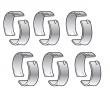
TRE529319 |
6 |
约翰迪尔(John Deere) 强鹿6081发动机主轴瓦(标准) |
|
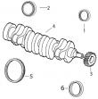
TRE529320 |
1 |
约翰迪尔(John Deere) 强鹿6081发动机止推瓦(标准) |
|
TRE506220 |
1 |
约翰迪尔(John Deere) 强鹿6081发动机大修包 |
|
TRE508156 |
6 |
约翰迪尔(John Deere) 强鹿6081发动机活塞缸套四配套,包括活塞,活塞环,活塞销,缸套,卡簧,阻水圈,低压缩 |
|
TRE520036 |
1 |
约翰迪尔(John Deere) 强鹿6081发动机SEAL, 曲轴 REAR |
|
型号 |
数量 |
描述 |
|
TR116081 |
6 |
约翰迪尔(John Deere) 强鹿6081发动机连杆瓦(标准 |
|
TR66452 |
12 |
约翰迪尔(John Deere) 强鹿6081发动机连杆螺钉 |
|
TR71918 |
1 |
约翰迪尔(John Deere) 强鹿6081发动机GASKET, OIL PAN |
|
TRE529319 |
6 |
约翰迪尔(John Deere) 强鹿6081发动机主轴瓦(标准) |
|
TRE529320 |
1 |
约翰迪尔(John Deere) 强鹿6081发动机止推瓦(标准) |
|
TRE506222 |
1 |
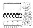
约翰迪尔(John Deere) 强鹿6081发动机GASKET, CYL HEAD SET |
|
TRE508156 |
6 |
约翰迪尔(John Deere) 强鹿6081发动机活塞缸套四配套,包括活塞,活塞环,活塞销,缸套,卡簧,阻水圈,低压缩 |
|
|
| 发动机和设备型号 |
低压缩活塞
4802 4806
发动机型号:
6081HF001
孔径:
4.56 in 116 mm
销径 Ø:
1.8742 in (+/- .0002) = 47 mm
连杆(米):
R116340 (To ESN 86,536)
R501034 (从 86,537)
| |
|
together. 3. use jdg1145 cylinder liner service set (a) with a 2.27 kg (5.0 lb) slide hammer (b) to remove cylinder liner. important: when using jdg1145 as shown (a) to remove liners, make sure puller is properly assembled before attempting to remove liners. step in bottom plate of puller assembly should fit in id of liner. do not over-tighten liner puller to remove liners. doing so could easily break liners. 4. install liner puller (c) in liner. 5. attach a 2.27 kg (5.0 lb) slide hammer (b) to liner puller as shown&remove liner. continued on next page ctm100 (20mar01) 02-030-15 powertech 10.5 l & 12.5 l diesel engines 032001 pn=155 cylinder block, liners, pistons,&rods 02 030 16 dpsg,ouo1004,1026 –19–09sep99–2/2 rg6668 –un–05dec97 cylinder liner packing a—square packing (neoprene) b—red o-ring (silicone) c—black o-ring (viton) d—cylinder block e—cylinder liner f—coolant passage 6. remove the cylinder liner square packing (a) from liner (e). 7. remove red o-ring (b)&black o-ring (c) from cylinder block (d). ctm100 (20mar01) 02-030-16 powertech 10.5 l & 12.5 l diesel engines 032001 pn=156 cylinder block, liners, pistons,&rods 02 030 17 rg,rg34710,110 –19–03aug99–1/2 visually inspect cylinder liners rg4643 –un–05dec97 liner visual inspection a—liner pitting b—erosion c—pitting depth is one-half liner thickness d—erosion depth is one-half packing step important: if pitting has occurred, check condition of coolant. 1. inspect exterior length of liner for pitting (a). check packing step for erosion (b). if pitting/erosion is observed, measure the depth of pits&erosion with a fine wire/needle. replace piston&liner if: ? pitting depth is one-half liner thickness (c)/more. specification cylinder liner wall—thickness 9.39—9.43 mm (0.370—0.371 in.) ? erosion depth is one-half packing step (d)/more. specification cylinder liner packing step— dimension 2.14—2.30 mm (0.084—0.090 in.) note: liners are reusable if the depth of pits/erosion is less than one-half the amount specified. when installing these liners, rotate 90° from original position. the liners should be deglazed&ring sets installed on pistons. continued on next page ctm100 (20mar01) 02-030-17 powertech 10.5 l & 12.5 l diesel engines 032001 pn=157 cylinder block, liners, pistons,&rods 02 030 18 rg,rg34710,110 –19–03aug99–2/2 rg1188 –un–04dec97 liner id inspection a—cracks in the flange area b—cracks in the ring travel area 2. visually examine liner id. replace piston&liner if: ? the crosshatch honing pattern is not visible immediately below the top ring turn-around area. ? liners are pitted/contain deep vertical scratches that can be detected by the fingernail. 3. carefully examine liner for signs of fatigue, such as fine cracks in the flange area (a)&cracks in the ring travel area (b). note: inspect block for cracks/erosion in the o-ring packing areas. (see inspect&clean cylinder block, later in this group.) 4. measure liner od&compare to following specifications. cylinder liners—specification flange area—od 151.565—151.615 mm (5.9671—5.9691 in.) upper od for seating liner—od 145.795—145.845 mm (5.7400—5.7419 in.) . water jacket area—od 144.73—144.99 mm (5.698—5.708 in.) lower od for seating with o-rings—od 140.397—140.447 mm (5.5274—5.5294 in.) . rg,rg34710,111 –19–30sep97–1/2 deglaze cylinder liners r26164 –un–13dec88 deglazing liners 1. secure cylinder liner in a holding fixture. see dfrg3— cylinder liner holding fixture, in section 05, group 190 for assembly of holding fixture. 2. use d17006br flexible cylinder hone to deglaze cylinder liner. note: use honing oil along with flex hone when deglazing liners. ctm100 (20mar01) 02-030-18 powertech 10.5 l & 12.5 l diesel engines 032001 pn=158 continued on next page cylinder block, liners, pistons,&rods 02 030 19 rg,rg34710,111 –19–30sep97–2/2 r26165 –un–13dec88 liner cross-hatch 3. use d17006br hone according to instructions supplied with tool to obtain a 45° cross-hatch pattern. thoroughly clean liners after deglazing. (see clean cylinder liners, next in this group.) rg,rg34710,112 –19–30sep97–1/1 clean cylinder liners 1. use a stiff bristle brush to remove all debris, rust, and scale from od of liners, under liner flange,&in o-ring packing areas. make certain there are no nicks or burrs in areas where packings will seat. important: do not use gasoline, kerosene, or commercial solvent to clean liners. solvents will not remove all the abrasives from liner walls. 2. thoroughly clean liner id with a 50 percent solution of hot water&liquid detergent. 3. rinse thoroughly&wipe dry with a clean rag. 4. swab out liner as many times as necessary with clean sae 10w oil. 5. clean liner until a white rag shows no discoloration. ctm100 (20mar01) 02-030-19 powertech 10.5 l & 12.5 l diesel engines 032001 pn=159 cylinder block, liners, pistons,&rods 02 030 20 rg,rg34710,113 –19–01nov00–1/1 cylinder liner manufacturing date code explanation rg6091 –un–27jan92 liner date code a manufacturing four-digit date code will appear on each liner. for example, sj96 15 means the liner has a non-hardened bore&was manufactured on the 15th day of october 1996. sj96 15 s . liner material type j month liner was manufactured 96 . year liner was manufactured 15 . day of month liner was manufactured liner material specification: s . non-hardened liner bore h . hardened liner bore month liner was manufactured a january b february c . march d april e . may f june g . july h . august i september j . october k november l december year liner was manufactured: 96 . 1996 97 . 1997 etc. ctm100 (20mar01) 02-030-20 powertech 10.5 l & 12.5 l diesel engines 032001 pn=160 cylinder block, liners, pistons,&rods 02 030 21 rg,rg34710,114 –19–01nov00–1/2 disassemble piston/rod assembly and clean piston rg8400 –un–22may98 removing piston pin snap ring note: piston&ring sizes differ between engines. piston part numbers are marked on top of pistons for identification. early engines engine piston ring size 10.5 l re52836, re504801 4 mm 12.5 l re66125 4 mm later engines 10.5 l re504343 3 mm 12.5 l re503969, 3 mm re505901 1. if necessary, check piston ring end gap prior to removing rings. specification no. 1 piston compression ring (4-mm rings)—end gap . 0.43—0.69 mm (0.017—0.027 in.) no. 2 piston compression ring (4-mm rings)—end gap . 1.01—1.27 mm (0.040—0.050 in.) no. 1 piston compression ring (3-mm rings)—end gap . 0.48—0.74 mm (0.019—0.029 in.) no. 2 piston compression ring (3-mm rings)—en, d gap . 1.35—1.65 mm (0.053—0.065 in.) 2. remove piston snap rings. remove piston pin and connecting rod from piston. note: discard snap rings. do not reuse. continued on next page ctm100 (20mar01) 02-030-21 powertech 10.5 l & 12.5 l diesel engines 032001 pn=161 cylinder block, liners, pistons,&rods 02 030 22 rg,rg34710,114 –19–01nov00–2/2 rg8367 –un–09dec97 removing piston rings a—jdg967 piston ring expander b—piston ring 3. remove piston rings (b) using the jdg967 piston ring expander (a). discard rings. caution: always follow manufacturer’s instructions,&safety steps exactly. 4. clean piston ring grooves using a piston ring groove cleaning tool. important: when washing pistons, always use a stiff bristle brush—not a wire brush—to loosen carbon residue. do not bead blast ring groove areas. 5. clean pistons by any of the following methods: ? immersion-solvent “d-part”. ? hydra-jet rinse gun. ? hot water with liquid detergent soap. if cleaning with hot water&liquid detergent, soak pistons in a 50 percent solution of liquid household detergent&hot water for 30 to 60 minutes. use a stiff bristle brush—not a wire brush—to loosen carbon residue. dry with compressed air. ctm100 (20mar01) 02-030-22 powertech 10.5 l & 12.5 l diesel engines 032001 pn=162 cylinder block, liners, pistons,&rods 02 030 23 rg,rg34710,115 –19–01nov00–1/1 check piston compression ring groove wear—6105 engines rg8373 –un–21may98 checking 6105 piston ring groove (jdg1019 shown on re52836 piston) rgr24201 –un–19nov97 jdg1019 ring groove wear gauge shown a—piston with worn ring groove b—keystone ring groove c—jdg1019 ring groove wear gauge d—ring land e—gauge shoulder f—piston with good ring groove note: earlier engines with re52836&re504801 pistons have 4-mm compression rings. later engines with re504343 pistons have 3-mm compression rings. piston part numbers are marked on top of pistons for identification. use the jdg1019 ring groove wear gauge on re52836 and re504801 pistons (early engines) to check wear of top two compression ring grooves. use the jdg1335 ring groove wear gauge on re504343 pistons (later engines) to check wear of top two compression ring grooves. check each groove at several locations. gauge shoulders should not contact ring land (d) of piston. if ring grooves are worn, replace piston&liner as a set. if ring grooves are good, proceed with piston inspection. ctm100 (20mar01) 02-030-23 powertech 10.5 l & 12.5 l diesel engines 032001 pn=163 cylinder block, liners, pistons,&rods 02 030 24 rg,rg34710,116 –19–01nov00–1/1 check piston compression ring groove wear—6125 engines rg8522 –un–10dec97 using jdg1022 - top groove rg8523 –un–10dec97 using jdg1022 - second groove a—jdg1022 ring groove wear gauge b—piston with good ring groove c—acceptable clearance d—piston with worn ring groove e—gauge shoulder contacting piston ring land note: earlier engines with&re66125 pistons have 4-mm compression rings. later engines with re503969&re505901 pistons have 3-mm compression rings. piston part numbers are marked on top of pistons for identification. the illustrations to the right shows use of jdg1022 wear gauge on earlier pistons. use of jdg1335 on later pistons is similar except the two compression ring grooves are the same on these pistons&only one side of the gauge is used to check both. check grooves at several locations around the circumference of piston crown. the word “top” on gauge should always face top of piston. earlier re66125 pistons with 4-mm rings: use the jdg1022 ring groove wear gauge 昆明JohnDeere密封圈修理包RE532713的价格,济南约翰迪尔活塞销R517073哪里买,亳州强鹿原厂进口缸套活塞批发商,海南强鹿柴油机启动马达RE523502价格行情,珠海约翰迪尔发动机配件配件哪家买,牡丹江强鹿启动机RE53186找哪家,清远约翰迪尔4045柴油机张紧轮哪里买,湘潭JohnDeere发动机活塞RE527039代理,赣州强鹿4045柴油机连杆哪里买,阿里强鹿滤芯滤清器RE21748哪家买,汕头强鹿曲轴齿轮R28811的价格,铜川约翰迪尔柴油发电机组启动马达代理商,黑河JohnDeere柴油机连杆瓦RE529318公司,徐州约翰迪尔6068柴油机凸轮轴衬套供货商,韶关JohnDeere气门锁夹R520798批发,海东强鹿6090柴油机四配套价格,巴音郭楞约翰迪尔强鹿3029柴油机气门弹簧座批发,聊城约翰迪尔8270R拖拉机发动机配件市场报价,信阳约翰迪尔R113612批发,淮安约翰迪尔强鹿节温器RE528652供货商,大理约翰迪尔柴油发电机组凸轮轴价格行情,河池强鹿柴油机加热器TRE502079批发,宜春强鹿消防柴油机配件市场报价,通辽约翰迪尔缸套密封水圈AR98850哪里买,黔西南约翰迪尔挖掘机单体泵一级代理,克孜勒苏约翰迪尔强鹿4045发动机内部修理套件信息,湘西约翰迪尔6068柴油机预热塞公司,拉萨强鹿柴油机AT21132止推轴承批发商,伊春强鹿柴油机曲轴瓦信息,北海约翰迪尔6081发动机齿环供货商,新界约翰迪尔联合收割机发动机柱塞公司,济宁强鹿柴油机凸轮轴批发价,宁德约翰迪尔拖拉机发动机发电机批发价,马鞍山约翰迪尔拖拉机发动机活塞销哪里买,衡水约翰迪尔3029DF128输油泵厂家供应,黄石JohnDeere柴油机活塞销R517073哪里买,茂名强鹿柴油机连杆瓦RE65908一级代理,阿拉善约翰迪尔6081柴油机机油泵哪家好,鹤壁强鹿曲轴齿轮R104587价格行情,吴忠强鹿柴油滤芯RE521248批发,昆明强鹿左平衡轴TRE500449厂家供应,荆门强鹿发动机喷油器公司,盐城约翰迪尔4105柴油机涡轮增压器厂家批发,廊坊供应美国原装6068约翰迪尔机油滤清器RE504836价格行情,海南强鹿柴油机启动马达RE523502价格,毕节约翰迪尔曲轴RE506195厂家供货,金昌强鹿6081柴油发动机前油封厂家批发,南充约翰迪尔传感器RE522794诚信推荐,南平约翰迪尔发动机放水阀供应商,梧州强鹿6090柴油发动机进气门厂家供应,九龙约翰迪尔发动机曲轴信息,昭通JohnDeere传感器RE167207诚信推荐,阿克苏强鹿柴油机连杆瓦厂家供货,萍乡强鹿R123461风扇皮带批发商,广元约翰迪尔4045柴油机输油泵哪家买,文山johndeere约翰迪尔强鹿柴油发动机废气热交换器RE521493厂家供应,深圳JohnDeere空气加热器厂家供应,(a), end marked “g1”, to check wear of top compression ring groove. use end marked “g2” of jdg1022 ring groove wear gauge to check wear of middle compression ring groove. if gauge shoulder contacts ring land of piston, ring groove is worn. replace piston&liner as a set. if ring grooves are good (b), proceed with piston inspection. later re503969&re505901 pistons with 3-mm rings: use jdg1335 ring groove wear gauge to check wear of top two compression rings. if gauge shoulder contacts ring land of piston, ring groove is worn. replace piston&liner as a set. if ring grooves are good (b), proceed with piston inspection. ctm100 (20mar01) 02-030-24 powertech 10.5 l & 12.5 l diesel engines 032001 pn=164 cylinder block, liners, pistons,&rods 02 030 25 rg,rg34710,117 –19–01nov00–1/1 check piston oil control ring groove wear—6105&6125 engines rg5234 –un–05dec97 measuring oil control ring groove wear note: piston&ring sizes differ between engines. piston part numbers are marked on top of pistons for identification. early engines engine piston oil control ring size 10.5 l re52836, re504801 4.8 mm 12.5 l re66125 4.8 mm later engines 10.5 l re504343 4 mm 12.5 l re503969, 4 mm re505901 1. check oil control ring-to-groove clearance by installing a new ring in groove. 2. measure clearance with a feeler gauge at several points. compare measurements with specifications given below. specification oil control ring-to-groove (re52836, re504801, re66125 pistons)—clearance 0.064—0.114 mm (0.0025—0.0045 in.) maximum clearance . 0.165 mm (0.0065 in.) oil control ring-to-groove (re504343, re503969 and re505901 pistons)—clearance 0.041—0.091 mm (0.0016—0.0036 in.) maximum clearance . 0.132 mm (0.0052 in.) note: replace piston&liner (as a set) if oil control ring clearance exceeds specifications given. ctm100 (20mar01) 02-030-25 powertech 10.5 l & 12.5 l diesel engines 032001 pn=165 cylinder block, liners, pistons,&rods 02 030 26 rg,rg34710,118 –19–13aug99–1/1 inspect piston pin&pin bore in piston rg5231 –un–05dec97 installing piston pin rg4984 –un–05dec97 piston pin bore inspection a—pin b—tapered bore c—opposite side of bore note: piston pin must be in good condition? worn beyond specification given below. 1. dip piston pin in clean engine oil. note: on 6125 engines, assemble piston crown and skirt. 2. install pin (a) through piston. pin should pass through piston using only light thumb pressure. 3. check taper in piston pin bore by inserting pin from both sides. if pin enters freely, but binds in the center, the bore could be tapered (b). 4. insert pin in piston to check for bore alignment. pin should not “click”/need to be forced into bore on opposite side (c). 5. measure piston pin&piston bore&compare to specifications. if either are not within specification, replace pin, piston,&liner. specification piston pin—od 50.772—50.787 mm (1.9989—1.9995 in.) . piston pin bore in piston (6105)—id 50.795—50.805 mm (1.9998—2.0002 in.) . piston skirt bushing (6125)—id 50.798—50.808 mm (1.9999—2.0003 in.) . piston crown bushing (6125)—id 50.810—50.825 mm (2.0004—2.0010 in.) ctm100 (20mar01) 02-030-26 powertech 10.5 l & 12.5 l diesel engines 032001 pn=166 cylinder block, liners, pistons,&rods 02 030 27 rg,rg34710,119 –19–13aug99–1/2 determine piston-to-liner clearance rg7403 –un–03nov97 measuring piston skirt a—bottom of piston dimension b—6105 skirt od 1. measure 6105 skirt od (b) at right angles to piston pin bore, 29.97 mm (1.180 in.) from the bottom of the piston (a). 2. measure 6125 engine skirt od at right angles to piston pin bore, 35.0 mm (1.38 in.) from bottom of skirt. 3. record measurement&compare measurement obtained from matching liner. specification piston skirt (6105)—od 29.97 mm (1.180 in.) from bottom of piston 126.872—126.898 mm (4.9950—4.9960 in.) . piston skirt (6125)—od 35.0 mm (1.380 in.) from bottom of skirt 126.910—126.930 mm (4.9965—4.9972 in.) . continued on next page ctm100 (20mar01) 02-030-27 powertech 10.5 l & 12.5 l diesel engines 032001 pn=167 cylinder block, liners, pistons,&rods 02 030 28 rg,rg34710,119 –19–13aug99–2/2 rg10049 –un–25may99 measuring liner id important: always measure liners at room temperature. 4. measure liner bore parallel to piston pin at top end of ring travel (a). 5. measure bore in same position at bottom end of ring travel (b). 6. measure bore at right angle to piston pin at top end of ring travel (c). 7. measure bore in same position at bottom end of ring travel (d). 8. compare measurements a, b, c,&d to determine if liner is tapered/out-of-round. 9. compare liner id with matched piston od. specification cylinder liner—id 126.990—127.010 mm (4.9996—5.0004 in.) . max. out of round . 0.020 mm (0.0008 in.) max. wear/taper (ring travel area) . 0.030 mm (0.0012 in.) piston-to-liner clearance (new part 6105)—clearance 0.092—0.138 mm (0.0036—0.0054 in.) max. acceptable wear . 0.152 mm (0.0060 in.) piston-to-liner clearance (new part 6125)—clearance 0.060—0.100 mm (0.0024—0.0039 in.) max. acceptable wear . 0.152 mm (0.0060 in.) replace piston&liners (as a set) if they exceed wear specifications given. ctm100 (20mar01) 02-030-28 powertech 10.5 l & 12.5 l diesel engines 032001 pn=168 cylinder block, liners, pistons,&rods 02 030 29 rg,rg34710,120 –19–30sep97–1/1 measure liner flange thickness rg8199 –un–21may98 measuring liner flange thickness measure cylinder liner flange thickness at several locations&compare with specification given below. if liner flange is not within specification, use liner shims or replace piston&liner as a set. specification cylinder liner flange—thickness 9.525—9.575 mm (0.3750—0.3770 in.) ctm100 (20mar01) 02-030-29 powertech 10.5 l & 12.5 l diesel engines 032001 pn=169 cylinder block, liners, pistons,&rods 02 030 30 rg,rg34710,121 –19–13aug99–1/3 inspect&measure connecting rod bearings rg10246 –un–30jul99 assembled rod with bearing a—rod cap b—rod c—bearings inspect rod bearings for damage of wear. important: never use new connecting rod cap screws when checking rod bearing id. use new cap screws only for final assembly of connecting rods. rod bearing-to-journal oil clearance can be checked with plastigage?, if rod is connected to crankshaft. if rod is out of engine, measure id of connecting rod bearings and compare with od of crankshaft journal. note: use plastigage? as directed by the manufacturer. the use of plastigage? will determine bearing journal clearance, but will not indicate the condition of either surface. 1. with crankshaft removed, measure connecting rod journal od at several points. 2. install connecting rod cap (a) on rod (b) with bearings (c) in correct position. 3. on tongue-and-groove connecting rods: initially tighten blind-hole cap screw, then, tighten open-hole cap screw to the following specifications. specification tongue-and-groove connecting rod cap screw—initial torque . 27 n?m (20 lb-ft) next, tighten rod cap screws to the following specifications. specification tongue-and-groove connecting rod cap screw—final torque 75 n?m (55 lb-ft) plus 90—100° turn clockwise . (see torque-turn connecting rod cap screws, later in this group.) plastigage is a registered trademark of dana corp. ctm100 (20mar01) 02-030-30 powertech 10.5 l & 12.5 l diesel engines 032001 pn=170 continued on next page cylinder block, liners, pistons,&rods 02 030 31 rg,rg34710,121 –19–13aug99–2/3 4. on precision joint? connecting rods: initially tighten rod cap screw closest to piston end, then tighten other cap screw to the following specifications. specification precision joint? connecting rod cap screw—torque 140 n?m (103 lb-ft) plus 90—100° turn clockwise (see torque-turn connecting rod cap screws, later in this group.) precision joint is a trademark of deere & company rg,rg34710,121 –19–13aug99–3/3 rg3824 –un–04dec97 measuring assembled rod bearing id a—inside micrometer 5. using an inside micrometer (a), measure assembled id of bearing. 6. subtract od of each crankshaft journal from id of each respective rod bearing to obtain oil clearance. 7. compare measurements with the specifications given. specification crankshaft rod journal—od 88.844—88.874 mm (3.4980—3.4990 in.) connecting rod bearing for crankshaft journal (assembled)—id 88.93—88.98 mm (3.501—3.502 in.) . connecting rod bearing-to-journal (new part)— oil clearance . 0.06—0.13 mm (0.002—0.005 in.) max. oil clearance . 0.15 mm (0.006 in.) 8. inspect connecting rod bearings for wear/damage. if bearings are worn/not within specification, replace both connecting rod bearing&rod pin bearing. ctm100 (20mar01) 02-030-31 powertech 10.5 l & 12.5 l diesel engines 032001 pn=171 cylinder block, liners, pistons,&rods 02 030 32 rg,rg34710,122 –19–02aug99–1/4 inspect connecting rod&cap rg3749 –un–04dec97 tongue-and-groove rod&cap rg10301 –un–27aug99 precision joint? rod&cap a—tongue-and-groove joints b—cap screw hole c—precision joint? mating surfaces 1. inspect rod&cap for wear/damage, such as chips or nicks in the joint areas (a). important: do not nick the joint surfaces of rod and cap. this is very critical on precision joint? rods to ensure proper seating. never scrape joint surfaces (c) with a wire brush/other tool; the interlocking mating surfaces must be preserved. 2. inspect in&around cap screw holes (b) in cap. if any defects are found, replace rod&cap. important: if replacing a connecting rod, use the same type of joint design. do not intermix precision joint? rods and tongue-and-groove rods on the same engine. see parts catalog for recommendations. precision joint is a trademark of deere & company continued on next page ctm100 (20mar01) 02-030-32 powertech 10.5 l & 12.5 l diesel engines 032001 pn=172 cylinder block, liners, pistons,&rods 02 030 33 rg,rg34710,122 –19–02aug99–2/4 rg4982 –un–05dec97 assembled rod without bearings 3. carefully clamp rod in a soft-jawed vise (cap end upward). important: never use new connecting rod cap screws when checking rod bearing id. use new cap screws only for final assembly of connecting rods. 4. install cap without bearing inserts. 5. on tongue-and-groove connecting rods: initially tighten blind-hole cap screw, then, tighten open-hole cap screw to the following specifications. specification tongue-and-groove connecting rod cap screw—initial torque . 27 n?m (20 lb-ft) next, tighten rod cap screws to the following specifications. specification tongue-and-groove connecting rod cap screw—final torque 75 n?m (55 lb-ft) plus 90—100° turn clockwise . (see torque-turn connecting rod cap screws, later in this group.) 6. on precision joint? connecting rods: initially tighten rod cap screw closest to piston end, then tighten other cap screw to the following specifications. specification precision joint? connecting rod cap screw—torque 140 n?m (103 lb-ft) plus 90—100° turn clockwise (see torque-turn connecting rod cap screws, later in this group.) precision joint is a trademark of deere & company continued on next page ctm100 (20mar01) 02-030-33 powertech 10.5 l & 12.5 l diesel engines 032001 pn=173 cylinder block, liners, pistons,&rods 02 030 34 rg,rg34710,122 –19–02aug99–3/4 rg1549 –un–20nov97 measuring assembled rod bore 7. using an inside micrometer, measure rod bore at center of bore&record measurements as follows: ? (a) at right angle to rod/cap joint. ? (b) at 45 degrees left of measurement (a). ? (c) at 45 degrees right of measurement (a). 8. compare the measurements. specification connecting rod bore (for crankshaft journal bearing)—id 93.76—93.79 mm (3.6915—3.6925 in.) if difference between the greatest&least measurement is more than 0.038 mm (0.0015 in.), the rod&cap are out of round. replace both connecting rod&cap. rg,rg34710,122 –19–02aug99–4/4 rg8420 –un–09dec97 measuring rod center-to-center bores a—rod’s piston pin bore-to-crankshaft bore center-to-center dimension 9. measure rod’s piston pin bore-to-crankshaft bore center-to-center dimension (a)&compare with specification given. if measurement is not within specification, replace rod. specification connecting rod centerline of piston pin bore-to-crankshaft bore (new part)—dimension 263.95—264.05 mm (10.392—10.396 in.) ctm100 (20mar01) 02-030-34 powertech 10.5 l & 12.5 l diesel engines 032001 pn=174 cylinder block, liners, pistons,&rods 02 030 35 rg,rg34710,123 –19–13aug99–1/2 inspect piston pins&rod bushings rg3172 –un–04dec97 a—connecting rod installing piston pin in rod bushing b—piston pin 1. insert piston pin (b) through piston pin bushing and carefully clamp in a soft-jawed vise. 2. rotate connecting rod (a) back&forth several times to make sure connecting rod moves freely on piston pin. 3. remove piston pin from connecting rod. continued on next page ctm100 (20mar01) 02-030-35 powertech 10.5 l & 12.5 l diesel engines 032001 pn=175 cylinder block, liners, pistons,&rods 02 030 36 rg,rg34710,123 –19–13aug99–2/2 rg4924 –un–20nov97 inspecting rod piston pin bushing bore a—tapered bore b—bell-mouthed bore 4. insert pin from either side of rod bushing. if pin is free on one end, but tight on the other, the bore could be tapered (a). if pin enters freely from both sides, but is tight in the center, bore is bell-mouthed (b). 5. inspect piston pin bushing lubrication hole in rod for damage, excessive wear/contaminants. 6. measure pin bushing id for specified clearance. specification piston pin—od 50.772—50.787 mm (1.9989—1.9995 in.) . rod pin bore without bushing— id 55.529—55.555 mm (2.1862—2.1872 in.) . installed rod pin bushing (before boring)—id 50.729—50.781 mm (1.9972—1.9992 in.) installed rod pin bushing (after boring)—id 50.805—50.830 mm (2.0002—2.0012 in.) piston pin bushing bore— out-of-round 0.038 mm (0.0015 in.) piston pin-to-bushing—oil clearance 0.017—0.059 mm (0.0007—0.0023 in.) max. acceptable wear . 0.076 mm (0.0030 in.) press fit of bushing in rod pin bore—press fit 0.100—0.163 mm (0.0039—0.0064 in.) . 7. if necessary, remove&replace piston pin bushing. (see remove piston pin bushing, clean, and inspect bushing bore in this group.) ctm100 (20mar01) 02-030-36 powertech 10.5 l & 12.5 l diesel engines 032001 pn=176 cylinder block, liners, pistons,&rods 02 030 37 rg,rg34710,124 –19–30sep97–1/1 remove piston pin bushing, clean, and inspect bushing bore rg4723 –un–20nov97 removing rod piston pin bushing a—jde98-8 cup b—jde98-10 bushing remover/installer c—std36104 forcing screw important: do not use pneumatic tools to remove or install piston pin bushing. use care to properly align the jde98-10 bushing remover/installer (b) with bushing so that the connecting rod is not damaged. 1. remove the used bushing with jde98-8 cup (a), jde98-10 bushing remover/installer,&std36104 forcing screw (c) from the jde98a connecting rod bushing service set. 2. clean rod bushing bore using a medium grit emery cloth, as burrs will distort bushing. install bushing on side opposite rod burr. 3. if necessary, file a slight chamfer around bushing bore to remove any sharp edges. chamfer will also aid in bushing installation. 4. measure rod bushing bore in three/more places approximately 45° apart. specification connecting rod pin bushing bore (without bushing)—id 55.529—55.555 mm (2.1862—2.1872 in.) connecting rod pin bushing— press fit in rod pin bore 0.100—0.163 mm (0.0039—0.0064 in.) . important: if piston pin bushing bore diameter is not within specification/bushing has spun in rod, discard rod&replace with a new one. ctm100 (20mar01) 02-030-37 powertech 10.5 l & 12.5 l diesel engines 032001 pn=177 cylinder block, liners, pistons,&rods 02 030 38 rg,rg34710,125 –19–30sep97–1/1 install piston pin bushing rg8421 –un–09dec97 installing rod piston pin bushing a—jde98-8 cup1 b—jde98-10 bushing remover/installer1 c—jde98-9 pilot1 d—std36104 forcing screw1 e—bushing f—jde98-6 pilot1 1. lubricate connecting rod bore with clean engine oil. important: do not use power tools to install bushing. 2. assemble jde98-10 bushing remover/installer (b) with jde98-9 pilot (c). install new bushing (e) onto driver. lubricate od of bushing. install&lubricate std36104 forcing screw threads (d). 3. assemble jde98-6 pilot (f) onto driver. 4. engage forcing screw heads with threads in jde98-8 cup (a)&install new bushing. important: boring the connecting rod bushing should be done only by experienced personnel on equipment capable of maintaining bushing finish specification. 5. precision bore new bushing to specification to obtain pin-to-bushing clearance. remove all debris from boring operation. specification piston pin bushing (after boring)—id 50.805—50.830 mm (2.0002—2.0012 in.) piston pin—od 50.772—50.787 mm (1.9989—1.9995 in.) . piston pin-to-bushing—clearance 0.017—0.059 mm (0.0007—0.0023 in.) 1 from jde98a connecting rod bushing service set. ctm100 (20mar01) 02-030-38 powertech 10.5 l & 12.5 l diesel engines 032001 pn=178 cylinder block, liners, pistons,&rods 02 030 39 rg,rg34710,126 –19–02aug99–1/1 complete disassembly of cylinder block (if required) if complete inspection&“hot tank” cleaning of cylinder block is 临沂约翰迪尔RE521348曲轴哪里买,钦州强鹿柴油机水泵AR97708的价格,合肥约翰迪尔连杆RE500608代理,陇南JohnDeere加大连杆瓦RE65909批发,抚顺johndeere约翰迪尔强鹿柴油机节温器厂家批发,衢州强鹿6081柴油发动机修理包找哪家,昌吉迪尔强鹿后油封re530121价格,鄂尔多斯强鹿柴油机曲轴RE505921市场报价,伊春约翰迪尔收割机RE51630空气滤芯多少钱,吴忠JOHNDEERE强鹿3029DF120配件厂家供货,泉州美国强鹿RE60021柴油滤芯诚信推荐,博尔塔拉强鹿RE170084皮带张紧轮批发商,高雄约翰迪尔曲轴齿轮R104587厂家供货,山南约翰迪尔挖掘机大修包厂家批发,required, refer to the appropriate group for removal of all external&internal mounted components listed below: 1. remove crankshaft&pulley if not previously removed. (see remove crankshaft in group 040.) 2. remove coolant pump&all remaining cooling system components. (see remove coolant pump in group 070.) 3. remove timing gear cover. (see remove timing gear cover in group 040.). remove front plate. (see remove&install cylinder block front plate earlier in this group.) 4. remove engine oil pump&all remaining lubrication system components. (see remove engine oil pump in group 060.) 5. remove all components (water gallery plugs, oil gallery plugs, bushings,&engine serial number plate) before inspecting&cleaning cylinder block. use jdg782 oil gallery plug tool to remove&install gallery plugs. ctm100 (20mar01) 02-030-39 powertech 10.5 l & 12.5 l diesel engines 032001 pn=179 cylinder block, liners, pistons,&rods 02 030 40 rg,rg34710,127 –19–09sep99–1/2 inspect&clean cylinder block rg8210 –un–21may98 cleaning head bolt threads in block note: all components, water gallery plugs,&oil gallery plugs must be removed from the cylinder block for inspection&cleaning. refer to the proper group for removal of all external and internal mounted components. 1. use d17015br o-ring groove cleaning brush/an equivalent brush to thoroughly clean all debris from cylinder liner o-ring bores. 2. remove cylinder head locating dowels, if not previously removed. clean out all threaded holes for cylinder head mounting cap screws in top deck of cylinder block. use jdg978 tap/an equivalent m16 x 2.0 tap approximately 152.4 mm (6.0 in.) long. use compressed air to remove any debris/fluid which may be present in the cap screw hole. important: if cylinder block is cleaned in a hot tank, be sure to remove any aluminum parts. aluminum parts can be damaged or destroyed by hot tank solutions. remove all serial number plates. 3. clean block thoroughly using cleaning solvent, pressure steam,/a hot tank. continued on next page ctm100 (20mar01) 02-030-40 powertech 10.5 l & 12.5 l diesel engines 032001 pn=180 cylinder block, liners, pistons,&rods 02 030 41 rg,rg34710,127 –19–09sep99–2/2 rg7142 –un–05dec97 liner counterbore depth rg10340 –un–09sep99 lap liner flange a—liner flange counterbore depth b—block c—liner support flange d—jdg1145 liner service set note: jdg1145 cylinder liner service set (d) can be used with lapping compound, as shown, to lap liner flange to blockKEY PART NO. PART NAME QTY SERIAL NO. F F F REMARKS
1 RE57151 FUEL LINE 1 X NO. 6
2 RE57150 FUEL LINE 1 X NO. 5
3 RE57149 FUEL LINE 1 X NO. 4
4 R71398 SCREW 5 X
R58186 CLAMP 10 X
R59305 STRAP 5 X
R61144 STRAP 5 X
R74030 CLAMP 1 X
5 RE57148 FUEL LINE 1 X NO. 3
6 RE57147 FUEL LINE 1 -081549 X NO. 2
RE502933 FUEL LINE 1 081550- X NO. 2
7 RE57146 FUEL LINE 1 -081549 , X NO. 1
RE502932 FUEL LINE 1 081550- X NO. 1
8 21H1463 CAP SCREW 2 X 0.190" X 7/8"
R59298 STRAP 1 X
R61145 STRAP 1 X
R120184 STRAP 1 X
R59297 HALF CLAMP 2 X
9 R59298 STRAP 1 X
R58186 CLAMP 1 X
R71212 CLAMP 1 X
R74804 CLAMP 1 X
R71398 SCREW 1 X
R61145 STRAP 1 X
R120182 STRAP 1 X
10 21H1463 CAP SCREW 1 X 0.190" X 7/8"
R59297 HALF CLAMP 2 X
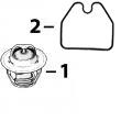
R59598 GASKET 2 X
11 RE55662 ABSORBER 1 X
12 24H1884 WASHER 1 X 13/32" X 13/16" X 0.120" 13/32" X
13/16" X 0.120", (NLR)
13 19M7166 CAP SCREW 1 X M10 X 20 M10 X 20
14 RE57152 INJECTION NOZZLE 6 X (A) (ROBERT BOSCH)
R51603 O-RING 6 X
15 R84472 WASHER 6 X 7.360 X 18.160 X 2 MM (0.290" X 0.715"
X 0.079") 7.360 X 18.160 X 2 MM
(0.290" X 0.715" X 0.079")
16 R504057 O-RING 6 087550- X
17 RE501970 ADAPTER 6 087550- X
18 R79604 TUBE NUT 6 087550- X
19 R51937 TUBE NUT 1 X
20 AR85519 PLUG 1 X
21 RE500803 FUEL LINE 1 087550- X
22 R77551 O-RING 6 -087549 X
23 R87082 FITTING 6 -087549 X
24 R79604 TUBE NUT 6 -087549 X
25 R79605 WASHER 6 -087549 X
26 R79606 TEE FITTING 6 -087549 X
27 R51936 SEALING WASHER 11 -087549 X
28 RE15807 FUEL LINE 2 -087549 X
29 RE15808 FUEL LINE 2 -087549 X
30 RE36421 FUEL LINE 2 -087549 X
31 R97061 TEE FITTING 1 -087549 X
(A) 2 ORANGE DOT
(2) POINT ORANGE
(2) ORANGEFARBENER PUNKT
(2) PUNTO ARANCIONE
(2) PUNTO ANARANJADO
(2) ORANGEFAERGAD PUNKT
KEY PART NO. PART NAME QTY SERIAL NO. F F F REMARKS
1 R60277 SNAP RING 1 X
2 R375R O-RING 1 X
3 R60279 NUT 1 X
4 R60278 SNAP RING 1 X
5 .. NOZZLE HOLDER 1 X (SUB RE61593)
6 R83720 WASHER 1 X 1.02 MM (.0402")
R83721 WASHER 1 X 1.08 MM (.0425")
R83722 WASHER 1 X 1.12 MM (.0441")
R83723 WASHER 1 X 1.18 MM (.0465")
R83724 WASHER 1 X 1.22 MM (.0480")
R83725 WASHER 1 X 1.28 MM (.0504")
R83726 WASHER 1 X 1.30 MM (.0512")
R83727 WASHER 1 X 1.38 MM (.0543")
R83728 WASHER 1 X 1.42 MM (.0559")
R83729 WASHER 1 X 1.48 MM (.0583")
R83730 WASHER 1 X 1.50 MM (.0591")
R83731 WASHER 1 X 1.58 MM (.0622")
R83732 WASHER 1 X 1.60 MM (.0630")
R83733 WASHER 1 X 1.68 MM (.0661")
R83734 WASHER 1 X 1.70 MM (.0669")
R83735 WASHER 1 X 1.78 MM (.0701")
R83736 WASHER 1 X 1.82 MM (.0717")
R83737 WASHER 1 X 1.88 MM (.0740")
R83738 WASHER 1 X 1.90 MM (.0748")
R83739 WASHER 1 X 1.98 MM (.0780")
7 R108699 SPRING 1 X
8 R108700 SEAT 1 X
9 R108701 PLATE 1 X
10 RE57153 NOZZLE 1 X (7 X .236)
11 R127176 NUT 1 X
12 R84472 WASHER 1 X
13 RE57152 INJECTION NOZZLE 6 X (A) (ROBERT BOSCH)
(A) (2) ORANGE DOT
(2) POINT ORANGE
(2) ORANGEFARBENER PUNKT
(2) PUNTO ARANCIONE
(2) PUNTO ANARANJADO
(2) ORANGEFAERGAD PUNKT
KEY PART NO. PART NAME QTY SERIAL NO. F F F REMARKS
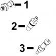
1 R51936 SEALING WASHER 1 X
2 RE30920 FUEL LINE 1 -035177 X
3 R97061 TEE FITTING 1 -035177 X
4 R67364 ELBOW FITTING 1 -035177 X
5 RE35684 FUEL LINE 1 -035177 X
6 RE30833 FUEL LINE 1 -035177 X
7 R91824 FITTING 1 -035177 X
8 R48693 WASHER 1 -035177 X
9 R51936 SEALING WASHER 3 035178- X
10 RE66000 FUEL LINE 1 035178-087549 X
RE501262 FUEL LINE 1 087550-090585 X (SUB RE504635)
RE504635 FUEL LINE 1 090586- X (SUB FOR RE501262)
11 RE67934 ADAPTER 1 035178- X
12 R63604 FITTING 1 035178-087549 X
RE502650 FITTING 1 087550- X (SUB FOR R63604)
13 R121195 CAP SCREW 4 X
14 R121164 GEAR 1 X
15 R76358 O-RING 1 X
16 R114130 STUD 4 X (SUB FOR R55396, THIS APPLICATION)
17 M72490 WASHER 4 X
18 14H1090 NUT 4 X
19 AR88903 ELBOW FITTING 1 X
20 R67264 PACKING 2 X
21 R79060 O-RING 1 X (SUB FOR R73858)
22 RE509065 OIL LINE 1 X (SUB FOR RE60577)
23 T18012 ELBOW FITTING 1 X
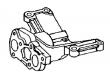
24 RE46375 FUEL PUMP 1 X (USE WITH RE62643)
25 51M4238 SEALING RING 1 X
26 RE28217 FUEL TEMPERATURE SENSOR 1 X (SUB FOR R53899, THIS APPLICATION)
27 R98500 O-RING 1 X
28 R89014 SOLENOID 1 X (B)
29 R99047 O-RING 1 X
30 RE61658 FUEL PUMP 1 -091883 X (A) (ROBERT BOSCH) (PES6P120A720RS3354)
RE503345 FUEL PUMP 1 091162- X (A) (ROBERT BOSCH)
31 12H296 WASHER 1 X 5.486 MM (0.216")
32 14M7297 NUT 1 X
(A) "SEE YOUR AUTHORIZED PUMP REPAIR STATION FOR PARTS NOT LISTED"
CONSULTEZ VOTRE REPARATEUR DE POMPE AGREE POUR LES PIECES NON CATALOGUE ES
NICHT GEZEIZTE TEILE VON PUMPENWERKSTAT BEZIEHEN
PER LE PARTI NON ELENCATE, RIVOLGETEVI AL CENTRO
CONSULTE CON SU ESTACION AUTORIZADA RE PEPARACIONES DE BOMBA
RAADGOER MED EN AUTORISERAD PUMPSERVICVERKSTAD BETRAEFFANDE EJ UPPTAGNA
 English
 Espaol
 Franais
 阿拉伯
阿拉伯 中文
中文 Deutsch
 Italiano
 Português
 日本
日本 韩国
韩国 български
 hrvatski
 esky
esky Dansk
Dansk Nederlands
 suomi
suomi Ελληνικ
 印度
印度 norsk
norsk Polski
 Roman
Roman русский
 Svenska