English
 Espaol
 Franais
 阿拉伯
阿拉伯 中文
中文 Deutsch
 Italiano
 Português
 日本
日本 韩国
韩国 български
 hrvatski
 esky
esky Dansk
Dansk Nederlands
 suomi
suomi Ελληνικ
 印度
印度 norsk
norsk Polski
 Roman
Roman русский
 Svenska
农业
640GIII
7210J
640H
7225J
648GIII
7430E
6830
7530
648H
7630
648HTJ
7730
748H
7830
748HTJ
7930
848H
9540IWTS
848HTJ
9560 STS
2954D
9570 STS
4730
9580I WTS
4830
S550 STS
5430
T550
7195J
W540

| 设备型号 | 备注 |
|---|---|
| 1270D | High Compression Piston. To ESN 199,999. Tier 1 |
| 703JH | 9.0 Liter Tier 2 & Tier 3 |
| 1470D | High Compression Piston. To ESN 199,999. Tier 1 |
| 753JH | 9.0 Liter Tier 2 & Tier 3 |
| 753 GL | High Compression Piston. To ESN 199,999. Tier 1 |
| 759J | 9.0 Liter Tier 2 & Tier 3 |
| 703JH | High Compression Piston. From ESN 200,000. Tier 2. |
| 759JH | 9.0 Liter Tier 2 & Tier 3 |
| 853JH | Low Compression Piston. From ESN 200,000. Tier 2. |
| 909KH | 9.0 Liter Tier 2 & Tier 3 |
| 903JH | Low Compression Piston. From ESN 200,000. Tier 2. |
| 1270G | 9.0 Liter Tier 2 & Tier 3 |
| 909JH | Low Compression Piston. From ESN 200,000. Tier 2. |
| 1470G | 9.0 Liter Tier 2 & Tier 3 |
| 1270D | 9.0 Liter Tier 2 & Tier 3 |
| 959K | 9.0 Liter Tier 2 & Tier 3 |
| 1270E | 9.0 Liter Tier 2 & Tier 3 |
| 1470D | 9.0 Liter Tier 2 & Tier 3 |
| 1470E | 9.0 Liter Tier 2 & Tier 3 |
约翰迪尔(John Deere) 强鹿6068D 6.8D RE59279/RE505101发动机大修包TRE66095
|
型号 |
数量 |
描述 |
|
TMX506 |
1 |
约翰迪尔(John Deere) 强鹿6068D发动机试剂盒 (6) |
|
TR114083 |
12 |
约翰迪尔(John Deere) 强鹿6068D发动机连杆螺钉 |
|
TR119874 |
1 |
约翰迪尔(John Deere) 强鹿6068D发动机凸轮轴衬套 |
|
TR123960 |
6 |
约翰迪尔(John Deere) 强鹿6068D发动机连杆衬套 PT 35 mm |
|
TRE31617 |
12 |
约翰迪尔(John Deere) 强鹿6068D发动机气门密封 STEM LITER ENG |
|
TRE44574 |
1 |
约翰迪尔(John Deere) 强鹿6068D发动机前油封 |
|
TRE501456 |
1 |
约翰迪尔(John Deere) 强鹿6068D发动机大修包 |
|
TRE505515 |
1 |
约翰迪尔(John Deere) 强鹿6068D发动机后油封 |
|
TRE65165 |
6 |
约翰迪尔(John Deere) 强鹿6068D发动机主轴瓦(标准) |
|
TRE65168 |
1 |
约翰迪尔(John Deere) 强鹿6068D发动机止推瓦(标准) |
|
TRE65908 |
6 |
约翰迪尔(John Deere) 强鹿6068D发动机连杆瓦(标准 |
|
TRE65966 |
6 |
约翰迪尔(John Deere) 强鹿6068D发动机活塞缸套四配套,包括活塞,活塞环,活塞销,缸套,卡簧,阻水圈 (RE59279) |
约翰迪尔(John Deere) 强鹿6068D 6.8D发动机大修包TRE66095A
|
型号 |
数量 |
描述 |
|
TMX506 |
1 |
约翰迪尔(John Deere) 强鹿6068D发动机试剂盒 (6) |
|
TR119874 |
1 |
约翰迪尔(John Deere) 强鹿6068D发动机凸轮轴衬套 |
|
TR123960 |
6 |
约翰迪尔(John Deere) 强鹿6068D发动机连杆衬套 PT 35 mm |
|
TR501124 |
12 |
约翰迪尔(John Deere) 强鹿6068D发动机连杆螺钉 |
|
TRE31617 |
12 |
约翰迪尔(John Deere) 强鹿6068D发动机气门密封 STEM LITER ENG |
|
TRE44574 |
1 |
约翰迪尔(John Deere) 强鹿6068D发动机前油封 |
|
TRE501456 |
1 |
约翰迪尔(John Deere) 强鹿6068D发动机大修包 |
|
TRE505515 |
1 |
约翰迪尔(John Deere) 强鹿6068D发动机后油封 |
|
TRE65165 |
6 |
约翰迪尔(John Deere) 强鹿6068D发动机主轴瓦(标准) |
|
TRE65168 |
1 |
约翰迪尔(John Deere) 强鹿6068D发动机止推瓦(标准) |
|
TRE65908 |
6 |
约翰迪尔(John Deere) 强鹿6068D发动机连杆瓦(标准 |
|
TRE65966 |
6 |
约翰迪尔(John Deere) 强鹿6068D发动机活塞缸套四配套,包括活塞,活塞环,活塞销,缸套,卡簧,阻水圈 (RE59279) |
约翰迪尔(John Deere) 强鹿6068D 6.8D发动机内部修理套件TIK66095
|
型号 |
数量 |
描述 |
|
TR114083 |
12 |
约翰迪尔(John Deere) 强鹿6068D发动机连杆螺钉 |
|
TR97344 |
1 |
约翰迪尔(John Deere) 强鹿6068D发动机GASKET, OIL PAN 6 CYL |
|
TRE31617 |
12 |
约翰迪尔(John Deere) 强鹿6068D发动机气门密封 STEM LITER ENG |
|
TRE65165 |
6 |
约翰迪尔(John Deere) 强鹿6068D发动机主轴瓦(标准) |
|
TRE65168 |
1 |
约翰迪尔(John Deere) 强鹿6068D发动机止推瓦(标准) |
|
TRE65908 |
6 |
约翰迪尔(John Deere) 强鹿6068D发动机连杆瓦(标准 |
|
TRE65966 |
6 |
约翰迪尔(John Deere) 强鹿6068D发动机活塞缸套四配套,包括活塞,活塞环,活塞销,缸套,卡簧,阻水圈 (RE59279) |
|
TRE66085 |
1 |
约翰迪尔(John Deere) 强鹿6068D发动机GASKET, CYL HEAD SET P.T. |
约翰迪尔(John Deere) 强鹿6068D 6.8D发动机TIK66095A
|
型号 |
数量 |
描述 |
|
TR501124 |
12 |
约翰迪尔(John Deere) 强鹿6068D发动机连杆螺钉 |
|
TR97344 |
1 |
约翰迪尔(John Deere) 强鹿6068D发动机GASKET, OIL PAN 6 CYL |
|
TRE31617 |
12 |
约翰迪尔(John Deere) 强鹿6068D发动机气门密封 STEM LITER ENG |
|
TRE65165 |
6 |
约翰迪尔(John Deere) 强鹿6068D发动机主轴瓦(标准) |
|
TRE65168 |
1 |
约翰迪尔(John Deere) 强鹿6068D发动机止推瓦(标准) |
|
TRE65908 |
6 |
约翰迪尔(John Deere) 强鹿6068D发动机连杆瓦(标准 |
|
TRE65966 |
6 |
约翰迪尔(John Deere) 强鹿6068D发动机活塞缸套四配套,包括活塞,活塞环,活塞销,缸套,卡簧,阻水圈 (RE59279) |
|
TRE66085 |
1 |
约翰迪尔(John Deere) 强鹿6068D发动机GASKET, CYL HEAD SET P.T. |
|
| ||||||||||||||||||||||||||||
(1)1件组合式密封和穿套; 取代TRE59810,RE538097。
(2)曲轴加工过程中必须保持适当的轴承轴颈半径,以保证正确的操作。
(3)曲轴(m)R116076,直鼻。
(4)曲轴(m)R503470,锥形鼻。
(5)检查应用程序是否正确使用。
(6)线路连接都是线程化的。
(7)线路连接是一个软管倒钩和一个螺纹。
(8)线路连接是两个软管倒钩。
(9)机器分体式和断裂式分体式连杆均可用于同一台发动机,但每个连杆必须使用正确的连杆螺栓。
强鹿JOHN DEERE柴油机配件、发动机配件、发电机组:
PE6068HF275BA5E、4045HFU82、4045HFU79、4045HF、6068HF183、6068HFU72、6090HFU75、6068HFUFU79、6068HFU82、6068HF183、6090HFU75、6068HFU74、6090HFU84、4024TF220、6090HF485 6081HF001、6081AF001、6081TF001dtcs, then clear all dtcs note: if dtcs spn 29 fmi 3/spn 29 fmi 4 are active, follow those dtcs first. 4. using the dst, monitor dtcs on the active code display parameter with: ? ignition on, engine off ? ignition on, engine running spn 28 fmi 3 reoccurs when engine is off and running: go to 2 spn 28 fmi 3 reoccurs only when engine is running: go to 3 spn 28 fmi 3 doesn’t reoccur: problem is intermittent. if no other codes are present, see intermittent fault diagnostics, earlier in this group. – – –1/1 2 throttle reference wire test note: for wiring&theory of operation information, see t11 - excavator throttle reference voltage high supporting information 1. ignition off 2. disconnect ecu 60-way connector 3. using a multimeter, measure voltage between terminal k3 in the harness end of the 60-way ecu connector&the ground stud of the pump&valve controller. 3.95 volts/less: go to 3 greater than 3.95 volts: short to power in throttle reference wire or faulty pump&valve controller connector or faulty pump&valve controller – – –1/1 3 ground test note: for wiring&theory of operation information, see t11 - excavator throttle reference voltage high supporting information there is a difference between the grounds of the ecu&pump&valve controller. check for loose ground connections at each controller. ctm188 (20mar01) 04-160-67 powertech 10.5 l & 12.5 l level 6 fuel system 032001 pn=255 trouble code diagnostics&tests 04 160 68 rg40854,0000005 –19–19dec00–1/1 level 6 ecu - t12 - excavator throttle reference voltage low rg11624 –19–19jan01 note: for more excavator throttle wiring information, refer to machine manual. important: do not force probes into connector terminals/damage will result. use jt07328 connector adapter test kit to make measurements in connectors. this will ensure that terminal damage does not occur. 450c lc excavator throttle ? the 450c lc excavator uses an analog throttle to measure throttle position. this throttle is connected to the pump&valve controller, which sends throttle input information to the ecu through a dedicated wire. since the ecu&pump&valve controller do not share a common ground, a throttle voltage reference wire&a throttle ground wire accompany the throttle input wire. the ecu calculates the differences in controller grounds in order to determine the throttle request by the pump and valve controller. this code will set if: ? the excavator throttle reference voltage to the ecu goes below 2.7 volts. if this code sets, the following will occur: ? the ecu will default the excavator throttle reference voltage to 3.75 volts. ctm188 (20mar01) 04-160-68 powertech 10.5 l & 12.5 l level 6 fuel system 032001 pn=256 trouble code diagnostics&tests ouo1004,0000c86 –19–08jan01–1/1 level 6 ecu - t12 - excavator throttle reference voltage low - continued – – –1/1 level 6 ecu - t12 - excavator throttle reference voltage low diagnostic procedure note: before using this diagnostic procedure, perform a preliminary inspection of 60-way ecu connector&the throttle sen*** connector looking for dirty, damaged,/poorly positioned terminals. 04 160 69 – – –1/1 1 intermittent fault test note: for wiring&theory of operation information, see t12 - excavator throttle reference voltage low supporting information 1. ignition on, engine off 2. using the dst, monitor dtcs on the active code display parameter 3. make note of any dtcs, then clear all dtcs note: if dtcs spn 29 fmi 3/spn 29 fmi 4 are active, follow those dtcs first. 4. using the dst, monitor dtcs on the active code display parameter with: ? ignition on, engine off ? ignition on, engine running spn 28 fmi 4 reoccurs when engine is off and running: go to 2 spn 28 fmi 4 reoccurs only when engine is running: go to 3 spn 28 fmi 4 doesn’t reoccur: problem is intermittent. if no other codes are present, see intermittent fault diagnostics, earlier in this group. – – –1/1 2 throttle reference wire test note: for wiring&theory of operation information, see t12 - excavator throttle reference voltage low supporting information 1. ignition off 2. disconnect ecu 60-way connector黔东南约翰迪尔RE172178液压油滤芯公司,永州JohnDeere进气门找哪家,阿拉善JohnDeere节温器R136063信息,呼和浩特johndeere约翰迪尔强鹿柴油发动机曲轴后油封RE53687代理,珠海强鹿柴油发电机组大修包代理,宜昌约翰迪尔6090柴油机排气门供应商,衡水JohnDeere气缸垫R525541批发商,澳门离岛强鹿柴油机泵头代理,兴安约翰迪尔联合收割机发动机大修包厂家供货,临沂约翰迪尔6090柴油机摇臂室盖垫片找哪家,吴忠JohnDeere前油封RE505515厂家供货,通化约翰迪尔输油泵RE517230多少钱,克孜勒苏约翰迪尔强鹿4045发动机内部修理套件代理商,南宁美国强鹿保养配件中心多少钱,铜仁约翰迪尔强鹿曲轴RE540429批发,阿坝强鹿滤芯滤清器RE26812B厂家批发,茂名JohnDeere水泵RE500734诚信推荐,六安JohnDeere加大止推轴承瓦RE65168B厂家批发,资阳JohnDeere摇臂室盖垫片R526607批发,沧州约翰迪尔6081发动机修理包厂家供货,惠州约翰迪尔强鹿3029柴油机气门弹簧厂家供货,荆州约翰迪尔6090柴油机凸轮轴铜衬套的价格,大连johndeere约翰迪尔强鹿柴油机齿轮室盖多少钱,恩施约翰迪尔发动机传感器找哪家,葫芦岛强鹿柴油机输油泵RE65265批发商,济南强鹿3029D配件代理商,广安约翰迪尔发动机连杆瓦批发,宜宾约翰迪尔节温器RE540550哪里买,绵阳JOHNDEER空气滤清器RE503852批发,云浮强鹿活塞环价格价格行情,四平约翰迪尔强鹿4045柴油机水泵垫片一级代理,连云港强鹿6090柴油发动机机油底壳垫片哪家好,酒泉约翰迪尔6081发动机后齿轮找哪家,海南强鹿柴油机启动马达RE523502诚信推荐,大兴安岭JOHNDEERE配件批发商,大庆约翰迪尔滑移装载机柴油机配件厂家供应,怒江约翰迪尔6068柴油机水泵盖批发,秦皇岛JohnDeere排气门TR90692诚信推荐,吉安JohnDeereel36936喷油器多少钱,蚌埠强鹿柴油发电机组全车线束哪家好,商洛johndeere约翰迪尔强鹿柴油发动机活塞环RE515941找哪家,菏泽强鹿柴油发电机组单体泵供应商,泰安johndeere约翰迪尔强鹿柴油发动机机滤RE530107供应商,台州约翰迪尔5-904拖拉机发动机配件厂家供应,北海约翰迪尔装载机发动机单体泵厂家供应,张家口强鹿发电机水泵总成AR97708厂家批发,香港岛约翰迪尔强鹿柴油机连杆市场报价,濮阳强鹿加大连杆瓦RE529318A供货商,长治强鹿电子燃油泵哪里买,三门峡JohnDeere气门锁夹R502371批发商,潮州约翰迪尔6068柴油机曲轴哪里买,荆门强鹿滤芯滤清器RE35522批发商,深圳强鹿后油封RE44574价格,恩施约翰迪尔RE526557滤芯价格行情,滁州johndeere约翰迪尔强鹿柴油发动机发动机修理包RE535190厂家批发,漳州强鹿柴油机止推片一级代理,西安约翰迪尔发动机高压油泵总成厂家价格,丽江约翰迪尔6090柴油机挺铜柱市场报价, 3. using a multimeter, measure voltage between terminal k3 in the harness end of the 60-way ecu connector&the ground pin of the pump&valve controller. 3.55 volts/greater: go to 3 less than 3.55 volts: open in throttle reference wire or faulty pump&valve connector or faulty pump&valve controller – – –1/1 3 ground test note: for wiring&theory of operation information, see t12 - excavator throttle reference voltage low supporting information there is a difference between the grounds of the ecu&pump&valve controller. check for loose ground connections at each controller. ctm188 (20mar01) 04-160-69 powertech 10.5 l & 12.5 l level 6 fuel system 032001 pn=257 trouble code diagnostics&tests 04 160 70 rg40854,0000006 –19–19dec00–1/1 level 6 ecu - t13 - excavator throttle ground voltage high rg11624 –19–19jan01 note: for more excavator throttle wiring information, refer to machine manual. important: do not force probes into connector terminals/damage will result. use jt07328 connector adapter test kit to make measurements in connectors. this will ensure that terminal damage does not occur. 450c lc excavator throttle ? the 450c lc excavator uses an analog throttle to measure throttle position. this throttle is connected to the pump&valve controller, which sends throttle input information to the ecu through a dedicated wire. since the ecu&pump&valve controller do not share a common ground, a throttle voltage reference wire&a throttle ground wire accompany the throttle input wire. the ecu calculates the differences in controller grounds in order to determine the throttle request by the pump and valve controller. this code will set if: ? the excavator throttle ground voltage to the ecu exceeds 3.0 volts. if this code sets, the following will occur: ? the ecu will default excavator throttle ground voltage to 2.5 volts. ctm188 (20mar01) 04-160-70 powertech 10.5 l & 12.5 l level 6 fuel system 032001 pn=258 trouble code diagnostics&tests ouo1004,0000c87 –19–08jan01–1/1 level 6 ecu - t13 - excavator throttle ground voltage high - continued – – –1/1 level 6 ecu - t13 - excavator throttle ground voltage high diagnostic procedure note: before using this diagnostic procedure, perform a preliminary inspection of 60-way ecu connector&the throttle sen*** connector looking for dirty, damaged,/poorly positioned terminals. 04 160 71 – – –1/1 1 intermittent fault test note: for wiring&theory of operation information, see t13 - excavator throttle ground voltage high supporting information 1. ignition on, engine off 2. using the dst, monitor dtcs on the active code display parameter 3. make note of any dtcs, then clear all dtcs 4. using the dst, monitor dtcs on the active code display parameter with: ? ignition on, engine off ? ignition on, engine running spn 29 fmi 3 reoccurs when engine is off and running: go to 2 spn 29 fmi 3 reoccurs only when engine is running: go to 3 spn 29 fmi 3 doesn’t reoccur: problem is intermittent. if no other codes are present, see intermittent fault diagnostics, earlier in this group. – – –1/1 2 throttle ground wire test note: for wiring&theory of operation information, see t13 - excavator throttle ground voltage high supporting information 1. ignition off 2. disconnect ecu 60-way connector 3. disconnect pump&valve connector 4. using a multimeter, measure resistance between terminal s1 in the harness end of the 60-way ecu connector&the throttle ground terminal of the pump&valve controller. 770 ohms/less: go to 3 greater than 770 ohms: short to power in throttle ground wire between ecu&750-ohm resistor or open in throttle ground wire or faulty 750-ohm resistor or faulty ecu connector or faulty ecu ctm188 (20mar01) 04-160-71 powertech 10.5 l & 12.5 l level 6 fuel system 032001 pn=259 trouble code diagnostics&tests – – –1/1 3 pump&valve controller test note: for wiring&theory of operation information, see t13 - excavator throttle ground voltage high supporting information 1. ignition off 2. disconnect 60-way ecu connector 3. using a multimeter, measure resistance between terminal s1 in the harness end of the 60-way ecu connector&the ground stud of the pump&valve controller. 770 ohms/less: go to 4 greater than 770 ohms: faulty pump&valve connector or faulty pump&valve controller 04 160 72 – – –1/1 4 ground test note: for wiring&theory of operation information, see t13 - excavator throttle ground voltage high supporting information there is a difference between the grounds of the ecu&pump&valve controller. check for loose ground connections at each controller. ctm188 (20mar01) 04-160-72 powertech 10.5 l & 12.5 l level 6 fuel system 032001 pn=260 trouble code diagnostics&tests 04 160 73 ctm188 (20mar01) 04-160-73 powertech 10.5 l & 12.5 l level 6 fuel system 032001 pn=261 trouble code diagnostics&tests 04 160 74 rg40854,0000007 –19–19dec00–1/1 level 6 ecu - t14 - excavator throttle ground voltage low rg11624 –19–19jan01 note: for more excavator throttle wiring information, refer to machine manual. important: do not force probes into connector terminals/damage will result. use jt07328 connector adapter test kit to make measurements in connectors. this will ensure that terminal damage does not occur. 450c lc excavator throttle ? the 450c lc excavator uses an analog throttle to measure throttle position. this throttle is connected to the pump&valve controller, which sends throttle input information to the ecu through a dedicated wire. since the ecu&pump&valve controller do not share a common ground, a throttle voltage reference wire&a throttle ground wire accompany the throttle input wire. the ecu calculates the differences in controller grounds in order to determine the throttle request by the pump and valve controller. this code will set if: ? the excavator throttle ground voltage to the ecu goes below 2.0 volts. if this code sets, the following will occur: ? the ecu will default excavator throttle ground voltage to 2.5 volts. ctm188 (20mar01) 04-160-74 powertech 10.5 l & 12.5 l level 6 fuel system 032001 pn=262 trouble code diagnostics&tests ouo1004,0000c88 –19–08jan, 01–1/1 level 6 ecu - t14 - excavator throttle ground voltage low - continued – – –1/1 level 6 ecu - t14 - excavator throttle ground voltage low diagnostic procedure note: before using this diagnostic procedure, perform a preliminary inspection of 60-way ecu connector&the throttle sen*** connector looking for dirty, damaged,/poorly positioned terminals. 04 160 75 – – –1/1 1 intermittent fault test note: for wiring&theory of operation information, see t14 - excavator throttle ground voltage low supporting information 1. ignition on, engine off 2. using the dst, monitor dtcs on the active code display parameter 3. make note of any dtcs, then clear all dtcs 4. using the dst, monitor dtcs on the active code display parameter with: ? ignition on, engine off ? ignition on, engine running spn 29 fmi 4 reoccurs when engine is off and running: go to 2 spn 29 fmi 4 reoccurs only when engine is running: go to 3 spn 29 fmi 4 doesn’t reoccur: problem is intermittent. if no other codes are present, see intermittent fault diagnostics, earlier in this group. – – –1/1 2 throttle ground wire test note: for wiring&theory of operation information, see t14 - excavator throttle ground voltage low supporting information 1. ignition off 2. disconnect ecu 60-way connector 3. using a multimeter, measure resistance between terminal s1 in the harness end of the 60-way ecu connector&the ground stud of the pump&valve controller. 730 ohms/greater: go to 3 less than 730 ohms: short to ground in throttle ground wire between ecu&750-ohm resistor or faulty ecu – – –1/1 3 ground test note: for wiring&theory of operation information, see t14 - excavator throttle ground voltage low supporting information there is a difference between the grounds of the ecu&pump&valve controller. check for loose ground connections at each controller. ctm188 (20mar01) 04-160-75 powertech 10.5 l & 12.5 l level 6 fuel system 032001 pn=263 trouble code diagnostics&tests 04 160 76 rg40854,0000008 –19–19dec00–1/1 level 6 ecu - t15 - excavator throttle input voltage high rg11624 –19–19jan01 note: for more excavator throttle wiring information, refer to machine manual. important: do not force probes into connector terminals/damage will result. use jt07328 connector adapter test kit to make measurements in connectors. this will ensure that terminal damage does not occur. 450c lc excavator throttle ? the 450c lc excavator uses an analog throttle to measure throttle position. this throttle is connected to the pump&valve controller, which sends throttle input information to the ecu through a dedicated wire. since the ecu&pump&valve controller do not share a common ground, a throttle voltage reference wire&a throttle ground wire accompany the throttle input wire. the ecu calculates the differences in controller grounds in order to determine the throttle request by the pump and valve controller. this code will set if: ? the excavator throttle input voltage to the ecu exceeds 4.9 volts. if this code sets, the following will occur: ? the ecu will use a default “limp-home” throttle value that will only allow idle engine speed. ctm188 (20mar01) 04-160-76 powertech 10.5 l & 12.5 l level 6 fuel system 032001 pn=264 trouble code diagnostics&tests ouo1004,0000c89 –19–08jan01–1/1 level 6 ecu - t15 - excavator throttle input voltage high - continued – – –1/1 level 6 ecu - t15 - excavator throttle input voltage high diagnostic procedure note: before using this diagnostic procedure, perform a preliminary inspection of 60-way ecu connector&the throttle sen*** connector looking for dirty, damaged,/poorly positioned terminals. 04 160 77 – – –1/1 1 intermittent fault test note: for wiring&theory of operation information, see t15 - excavator throttle input voltage high supporting information 1. ignition on, engine off 2. using the dst, monitor dtcs on the active code display parameter 3. make note of any dtcs, then clear all dtcs note: if dtcs spn 29 fmi 3/spn 29 fmi 4 are active, follow those dtcs first. 4. using the dst, monitor dtcs on the active code display parameter with: ? ignition on, engine off ? ignition on, engine running spn 91 fmi 3 reoccurs when engine is off and running: go to 2 spn 91 fmi 3 reoccurs only when engine is running: go to 3 spn 91 fmi 3 doesn’t reoccur: problem is intermittent. if no other codes are present, see intermittent fault diagnostics, earlier in this group. – – –1/1 2 throttle signal wire test note: for wiring&theory of operation information, see t15 - excavator throttle input voltage high supporting information 1. ignition off 2. disconnect ecu 60-way connector 3. using a multimeter, measure voltage between terminal k1 in the harness end of the 60-way ecu connector&the ground stud of the pump&valve controller. 4.0 volts/less: go to 3 greater than 4.0 volts: short to power in throttle signal wire or faulty pump&valve connector or faulty pump&valve controller – – –1/1 3 ground test note: for wiring&theory of operation information, see t15 - excavator throttle input voltage high supporting information there is a difference between the grounds of the ecu&pump&valve controller. check for loose ground connections at each controller. ctm188 (20mar01) 04-160-77 powertech 10.5 l & 12.5 l level 6 fuel system 032001 pn=265 trouble code diagnostics&tests 04 160 78 rg40854,0000009 –19–19dec00–1/1 level 6 ecu - t16 - excavator throttle input voltage low rg11624 –19–19jan01 note: for more excavator throttle wiring information, refer to machine manual. important: do not force probes into connector terminals/damage will result. use jt07328 connector adapter test kit to make measurements in connectors. this will ensure that terminal damage does not occur. 450c lc excavator throttle ? the 450c lc excavator uses an analog throttle to measure throttle position. this throttle is connected to the pump&valve controller, which sends throttle input information to the ecu through a dedicated wire. since the ecu&pump&valve controller do not share a common ground, a throttle voltage reference wire&a throttle ground wire accompany the throttle input wire. the ecu calculates the differences in controller grounds in order to determine the throttle request by the pump and valve controller. this code will set if: ? the excavator throttle input voltage to the ecu goes below 0.1 volts. if this code sets, the following will occur: ? the ecu will use a default “limp-home” throttle value that will only allow idle engine speed. ctm188 (20mar01) 04-160-78 powertech 10.5 l & 12.5 l level 6 fuel system 032001 pn=266 trouble code diagnostics&tests ouo1004,0000c8a –19–08jan01–1/1 level 6 ecu - t16 - excavator throttle input voltage low - continued – – –1/1 level 6 ecu - t16 - excavator throttle input voltage low diagnostic procedure note: before using this diagnostic procedure, perform a preliminary inspection of 60-way ecu connector&the throttle sen*** connector looking for dirty, damaged,/poorly positioned terminals. 04 160 79 – – –1/1 1 intermittent fault test note: for wiring&theory of operation information, see t16 - excavator throttle input voltage low supporting, information 1. ignition on, engine off 2. using the dst, monitor dtcs on the active code display parameter 3. make note of any dtcs, then clear all dtcs note: if dtcs spn 29 fmi 3/spn 29 fmi 4 are active, follow those dtcs first. 4. using the dst, monitor dtcs on the active code display parameter with: ? ignition on, engine off ? ignition on, engine running spn 91 fmi 4 reoccurs when engine is off and running: go to 2 spn 91 fmi 4 reoccurs only when engine is running: go to 3 spn 91 fmi 4 doesn’t reoccur: problem is intermittent. if no other codes are present, see intermittent fault diagnostics, earlier in this group. – – –1/1 2 throttle signal wire test note: for wiring&theory of operation information, see t16 - excavator throttle input voltage low supporting information 1. ignition off 2. disconnect ecu 60-way connector 3. using a multimeter, measure voltage between terminal k1 in the harness end of the 60-way ecu connector&the ground stud of the pump&valve controller. 1.0 volts/greater: go to 3 less than 1.0 volts: open in throttle signal wire or faulty pump&valve connector or faulty pump&valve controller – – –1/1 3 ground test note: for wiring&theory of operation information, see t16 - excavator throttle input voltage low supporting information there is a difference between the grounds of the ecu&pump&valve controller. check for loose ground connections at each controller. ctm188 (20mar01) 04-160-79 powertech 10.5 l & 12.5 l level 6 fuel system 032001 pn=267 trouble code diagnostics&tests 04 160 80 dpsg,rg40854,300 –19–21nov00–1/1 level 6 ecu - dtc spn 94 fmi 1 fuel supply pressure extremely low rg10393 –19–19dec00 note: wiring diagram shows oem engine applications. for wiring information non-oem engines, refer to machine manual. fuel pressure sen*** ? the fuel pressure sen*** uses a pressure transducer to measure the fuel pressure before the transfer pump. it is located in a fuel manifold behind the fuel filter. the fuel pressure intake voltage varies as fuel pressure varies. as the pressure increases, the input voltage to the ecu increases. for further fuel sen*** information, see measuring pressure in section 03, group 140. dtc spn 94 fmi 1 will set if: ? the fuel pressure is below 200 kpa (29 psi) (2 bar) at any engine speed. if dtc spn 94 fmi 1 sets, the following will occur: ? ecus that have engine protection with shutdown: – will severely derate the engine (dtc spn 1569 fmi 31 will also be present). if fuel pressure does not set within the shutdown value within 30 seconds, the ecu will shut down the engine. note: for oem applications, the engine derates 20% per minute until the engine has been derated by 40%. ? ecus that have engine protection without shutdown: – will severely derate the engine (dtc spn 1569 fmi 31 will also be present), but will not shut the engine down. note: for oem applications, the engine derates 20% per minute until the engine has been derated by 40%. ? ecus that have no engine protection: – there will be no derate&the ecu will not shut the engine down. ctm188 (20mar01) 04-160-80 powertech 10.5 l & 12.5 l level 6 fuel system 032001 pn=268 trouble code diagnostics&tests ouo1004,0000c8c –19–08jan01–1/1 level 6 ecu - dtc spn 94 fmi 1 fuel supply pressure extremely low - continued – – –1/1 level 6 ecu - dtc spn 94 fmi 1 fuel supply pressure extremely low diagnostic procedure note: before using this diagnostic procedure, perform a preliminary inspection of the 60-way ecu connector and the fuel pressure sen*** connector looking for dirty, damaged,/poorly positioned terminals. 04 160 81 – – –1/1 1 dtc spn 94 fmi 1 - preliminary test before using this diagnostic procedu, re, check for the following that could cause/be mistaken as low fuel pressure: 1. if fuel system has been recently opened (filter changed, line removed etc.), check affected o-rings on fitting&filter for air leaks. 2. if no leaks detected, perform fuel system bleed procedure. see bleed single rail fuel system in group 150&retest. 3. check fuel quantity. 4. check for ruptured fuel line. no problem found: go to 2 problem found: repair and retest. – – –1/1 2 fuel supply pressure test note: for wiring&theory of operation information, see dtc spn 94 fmi 1 fuel supply pressure extremely low supporting information. 1. connect a 0-1000 kpa (0-150 psi) gauge to the quick disconnect after removing the dust cap&cleaning the quick disconnect. 2. start engine&check fuel pressure at idle&at rated speed. if engine won’t start, check fuel pressure while cranking. see check single rail fuel supply pressure in group 150. fuel pressure specifications: ? cranking: 135-175 kpa (20-25 psi) ? idle: 410-555 kpa (60-80 psi) ? rated speed: 480-620 kpa (70-90 psi) fuel pressure below specification for any condition: check fuel system for low supply pressure. see check single rail fuel supply pressure in group 150. fuel pressure within specification for all conditions: verify that fuel pressure sen*** 5 v supply, input, and ground circuits are ok. if fuel pressure sen*** circuits are ok, replace fuel pressure sen*** and retest. ctm188 (20mar01) 04-160-81 powertech 10.5 l & 12.5 l level 6 fuel system 032001 pn=269 trouble code diagnostics&tests 04 160 82 dpsg,rg40854,301 –19–26aug99–1/1 level 6 ecu - dtc spn 94 fmi 3 fuel supply pressure input voltage high rg10393 –19–19dec00 note: wiring diagram shows oem engine applications. for wiring information non-oem engines, refer to machine manual. fuel pressure sen*** ? the fuel pressure sen*** uses a pressure transducer to measure the fuel pressure before the transfer pump. it is located in a fuel manifold behind the fuel filter. the fuel pressure intake voltage varies as fuel pressure varies. as the pressure increases, the input voltage to the ecu increases. for further fuel sen*** information, see measuring pressure in section 03, group 140. dtc spn 94 fmi 3 will set if: ? the fuel pressure input voltage exceeds 4.75 volts. this voltage corresponds to a pressure that is higher than what is physically possible for fuel pressure. if dtc spn 94 fmi 3 sets, the following will occur: ? ecu’s fuel pressure engine protection feature disabled. ctm188 (20mar01) 04-160-82 powertech 10.5 l & 12.5 l level 6 fuel system 032001 pn=270 trouble code diagnostics&tests ouo1004,0000c8d –19–08jan01–1/1 level 6 ecu - dtc spn 94 fmi 3 fuel supply pressure input voltage high - continued – – –1/1 level 6 ecu - dtc spn 94 fmi 3 fuel supply pressure input voltage high diagnostic procedure note: before using this diagnostic procedure, perform a preliminary inspection of the 60-way ecu connector and the fuel pressure sen*** connector looking for dirty, damaged,/poorly positioned terminals. 04 160 83 – – –1/1 1 intermittent fault test note: for wiring&theory of operation information, see dtc spn 94 fmi 3 fuel supply pressure input voltage high supporting information 1. warm engine 2. ignition on, engine running 3. using the dst, read the fuel pressure voltage parameter 4.75 v/greater: go to 2 below 4.75 v: problem is intermittent. if no other codes are present, see intermittent fault diagnostics, earlier in this group. – – –1/1 2 fuel pressure signal shorted test note: for wiring&theory of operation information, see dtc spn 94 fmi 3 fuel supply pressure input voltage high supporting information 1. ignition off 2. disconnect fuel pressure sen*** connector 3. ignition on, engine off 4. using the dst, read the fuel pressure voltage parameter below 0.25 v: go to 3 0.25 v/greater: short to voltage in fuel pressure sen*** signal circuit or faulty ecu ctm188 (20mar01) 04-160-83 powertech 10.5 l & 12.5 l level 6 fuel system 032001 pn=271 trouble code diagnostics&tests 04 160 84 – – –1/1 3 fuel pressure ground circuit open test note: for wiring&theory of operation information, see dtc spn 94 fmi 3 fuel supply pressure input voltage high supporting information probe fuel pressure sen*** ground (terminal a) in sen*** harness connector with a test light connected to battery voltage light on: faulty fuel pressure sen*** or faulty ecu connection or faulty ecu light off: open in fuel pressure sen*** ground circuit or faulty ecu connection or faulty ecu ctm188 (20mar01) 04-160-84 powertech 10.5 l & 12.5 l level 6 fuel system 032001 pn=272 trouble code diagnostics&tests 04 160 85 ctm188 (20mar01) 04-160-85 powertech 10.5 l & 12.5 l level 6 fuel system 032001 pn=273 trouble code diagnostics&tests 04 160 86 dpsg,rg40854,302 –19–26aug99–1/1 level 6 ecu - dtc spn 94 fmi 4 fuel supply pressure input voltage low rg10393 –19–19dec00 note: wiring diagram shows oem engine applications. for wiring information non-oem engines, refer to machine manual. fuel pressure sen*** ? the fuel pressure sen*** uses a pressure transducer to measure the fuel pressure before the transfer pump. it is located in a fuel manifold behind the fuel filter. the fuel pressure intake voltage varies as fuel pressure varies. as the pressure increases, the input voltage to the ecu increases. for further fuel sen*** information, see measuring pressure in section 03, group 140. dtc spn 94 fmi 4 will set if: ? the fuel pressure input voltage drops below 0.25 volts. this voltage corresponds to a pressure that is lower than what is physically possible for fuel pressure. if dtc spn 94 fmi 4 sets, the following will occur: ? ecu’s fuel pressure engine protection feature disabled. ctm188 (20mar01) 04-160-86 powertech 10.5 l & 12.5 l level 6 fuel system 032001 pn=274 trouble code diagnostics&tests ouo1004,0000c8e –19–08jan01–1/1 level 6 ecu - dtc spn 94 fmi 4 fuel supply pressure input voltage low - continued – – –1/1 level 6 ecu - dtc spn 94 fmi 4 fuel supply pressure input voltage low diagnostic procedure note: before using this diagnostic procedure, perform a preliminary inspection of 60-way ecu connector&the fuel pressure sen*** connector, looking for dirty, damaged,/poorly positioned terminals. 04 160 87 – – –1/1 1 intermittent fault test note: for wiring&theory of operation information, see dtc spn 94 fmi 4 fuel supply pressure input voltage low supporting information 1. warm engine 2. ignition on, engine running 3. using the dst, read the fuel pressure voltage parameter 0.25 v/less: go to 2 above 0.25 v: problem is intermittent. if no other codes are present, see intermittent fault diagnostics, earlier in this group. – – –1/1 2 fuel pressure wiring test note: for wiring&theory of operation information, see dtc spn 94 fmi 4 fuel supply pressure input voltage low supporting information 1. ignition off 2. disconnect fuel pressure sen*** connector 3. install a jumper wire between terminal b&terminal c in fuel pressure sen*** harness connector 4. ignition on, engine off 5. using the dst, read the fuel pressure voltage parameter in the diagnostic software below 4.75: v go to 3 4.75 v/greater: faulty fuel pressure sen*** connection or faulty fuel pressure sen*** ctm188 (20mar01) 04-160-87 powertech 10.5 l & 12.5 l level 6 fuel system 032001 pn=275 trouble code diagnostics&tests 04 160 88 – – –1/1 3 fuel pressure 5 v supply test note: for wiring&theory of operation information, see dtc spn 94 fmi 4 fuel supply pressure input voltage low supporting information 1. ignition off 2. remove jumper wire 3. ignition on, engine off 4. using a multimeter, measure voltage between fuel pressure sen*** 5 v supply terminal (terminal b) in sen*** harness connector&a good chassis ground 4.0 - 6.0 v: open in fuel pressure sen*** input circuit or short to ground in fuel pressure sen*** input circuit or faulty ecu connection or faulty ecu below 4.0 v: open in fuel pressure sen*** 5 v supply circuit or short to ground in fuel pressure sen*** 5 v supply circuit or faulty ecu connection or faulty ecu ctm188 (20mar01) 04-160-88 powertech 10.5 l & 12.5 l level 6 fuel system 032001 pn=276 trouble code diagnostics&tests 04 160 89 ctm188 (20mar01) 04-160-89 powertech 10.5 l & 12.5 l level 6 fuel system 032001 pn=277 trouble code diagnostics&tests 04 160 90 dpsg,rg40854,303 –19–21nov00–1/1 level 6 ecu - dtc spn 94 fmi 16 fuel supply pressure moderately high rg10393 –19–19dec00 note: wiring diagram shows oem engine applications. for wiring information non-oem engines, refer to machine manual. fuel pressure sen*** ? the fuel pressure sen*** uses a pressure transducer to measure the fuel pressure before the transfer pump. it is located in a fuel manifold behind the fuel filter. the fuel pressure intake voltage varies as fuel pressure varies. as the pressure increases, the input voltage to the ecu increases. for further fuel sen*** information, see measuring pressure in section 03, group 140. dtc spn 94 fmi 16 will set if: ? the ecu senses a fuel pressure above the warning value set point in the ecu. the warning value set point is dependent of engine speed. if dtc spn 94 fmi 16 sets, the following will occur: ? ecu’s that have engine protection: – will derate the engine (dtc spn 1569 fmi 31 will also be present) 2% per minute to a maximum derate of 20%. when fuel pressure drops back below the maximum value set point, power will be increased 2% per minute until either full power is reached/if the maximum value set point is surpassed again. note: the derate program shown applies to oem engine applications that contain engine protection. other applications may have a similar derate program. refer to specific machine manual for application derate programs. ctm188 (20mar01) 04-160-90 powertech 10.5 l & 12.5 l level 6 fuel system 032001 pn=278 trouble code diagnostics&tests ouo1004,0000c8f –19–08jan01–1/1 level 6 ecu - dtc spn 94 fmi 16 fuel supply pressure moderately high - continued – – –1/1 level 6 ecu - dtc spn 94 fmi 16 fuel supply pressure moderately high diagnostic procedure note: before using this diagnostic procedure, perform a preliminary inspection of the 60-way ecu connector and the fuel pressure sen*** connector looking for dirty, damaged,/poorly positioned terminals. 04 160 91 – – –1/1 1 fuel supply pressure test note: for wiring&theory of operation information, see dtc spn 94 fmi 16 fuel supply pressure moderately high supporting information 1. connect a 0-1000 kpa (0-150 psi) gauge to the quick connect after removing the dust cap&cleaning the quick connect. 2. start engine&check fuel pressure at idle&at rated speed. 3. if engine won’t start, check fuel pressure while cranking. see check single rail fuel supply pressure in group 150. above 410-480 kpa (60-70 psi) @ idle; 500-600 kpa (70-90 psi) @ rated speed: faulty high pressure regulating valve below 410-555 kpa (60-80 psi) @ idle; 480-620 kpa (70-90 psi) @ rated speed: plugged 100 micron internal housing screen 410-555 kpa (60-80 psi) @ idle; 480-620 kpa (70-90 psi) @ rated speed: verify that fuel pressure sen*** 5 v supply, input, and ground circuits are ok. if fuel pressure sen*** circuits are ok, replace fuel pressure sen*** and retest ctm188 (20mar01) 04-160-91 powertech 10.5 l & 12.5 l level 6 fuel system 032001 pn=279 trouble code diagnostics&tests 04 160 92 dpsg,rg40854,304 –19–21nov00–1/1 level 6 ecu - dtc spn 94 fmi 18 fuel supply pressure moderately low rg10393 –19–19dec00 note: wiring diagram shows oem engine applications. for wiring information non-oem engines, refer to machine manual. fuel pressure sen*** ? the fuel pressure sen*** uses a pressure transducer to measure the fuel pressure before the transfer pump. it is located in a fuel manifold behind the fuel filter. the fuel pressure intake voltage varies as fuel pressure varies. as the pressure increases, the input voltage to the ecu increases. for further fuel sen*** information, see measuring pressure in section 03, group 140. dtc spn 94 fmi 18 will set if: ? the fuel pressure is below 300 kpa (43.5 psi) (3 bar) at any engine speed. if dtc spn 94 fmi 18 sets, the following will occur: ? ecu’s that have engine protection: – will derate the engine (dtc spn 1569 fmi 31 will also be present) at 2% per minute to a maximum derate of 20%. when fuel pressure increases above the minimum value set point, power will be increased 2% per minute until full power is reached/fuel pressure drops below the minimum value set point again. – if in spite of the derate, fuel pressure continues to drop, ecus that have engine protection with shutdown will shut the engine down when fuel pressure drops below the shutdown value set point in the ecu. the shutdown value set point is dependent on engine speed. note: the derate program shown applies to oem engine applications that contain engine protection. other applications may have a similar derate program. refer to specific machine manual for application derate programs. ctm188 (20mar01) 04-160-92 powertech 10.5 l & 12.5 l level 6 fuel system 032001 pn=280 trouble code diagnostics&tests ouo1004,0000c90 –19–08jan01–1/1 level 6 ecu - dtc spn 94 fmi 18 fuel supply pressure moderately low - continued – – –1/1 level 6 ecu - dtc spn 94 fmi 18 fuel supply pressure moderately low diagnostic procedure note: before using this diagnostic procedure, perform a preliminary inspection of the 60-way ecu connector and the fuel pressure sen*** connector looking for dirty, damaged,/poorly positioned terminals. 04 160 93 – – –1/1 1 dtc spn 94 fmi 18 - preliminary test before using this diagnostic procedure, check for the following that could cause/be mistaken as low fuel pressure: 1. if fuel system has been recently opened (filter changed, line removed etc.), check affected o-rings on fitting&filter for air leaks. 2. if no leaks detected, perform fuel system bleed procedure. see bleed single rail fuel system in group 150&retest. 3. check fuel quantity 4. check for ruptured fuel line no problem found: go to 2 problem found: repair and retest. – – –1/1 2 fuel supply pressure test note: for wiring&theory of operation information, see dtc spn 94 fmi 18 fuel supply pressure moderately low supporting information 1. connect a 0-1000 kpa (0-150 psi) gauge to the quick connect after removing the dust cap&cleaning the quick connect. 2. start engine&check fuel pressure at idle&at rated speed. if engine won’t start, check fuel pressure while cranking. see check single rail fuel supply pressure in group 150. fuel pressure specifications: ? cranking: 135-175 kpa (20-25 psi) ? idle: 410-555 kpa (60-80 psi) ? rated speed: 480-620 kpa (70-90 psi) fuel pressure below specification for any condition: check fuel system for low supply pressure. see check single rail fuel supply pressure in group 150. fuel pressure within specification for all conditions: verify that fuel pressure sen*** 5 v supply, input, and ground circuits are ok. if fuel pressure sen*** circuits are ok, replace fuel pressure sen*** and retest. ctm188 (20mar01) 04-160-93 powertech 10.5 l & 12.5 l level 6 fuel system 032001 pn=281 trouble code diagnostics&tests 04 160 94 dpsg,rg40854,305 –19–26aug99–1/1 level 6 ecu - dtc spn 97 fmi 0 water in fuel continuously detected rg10394 –19–19dec00 note: wiring diagram shows oem engine applications. for wiring information non-oem engines, refer to machine manual. wif (water in fuel) sen*** ? the wif sen*** uses the resistance of water and fuel to detect the presence of water in the fuel system. this uses the principle that water is a better conductor of electricity than fuel is. because of this, the water in fuel sen*** will read a lower voltage when water is present than when it is not present. for further wif sen*** information, see water in fuel sen*** in section 03, group 140. dtc spn 97 fmi 0 will set if: ? the wif is above a predetermined quantity for an extended period of time. if dtc spn 97 fmi 0 sets, the following will occur: ? ecu’s that have engine protection with shutdown: – will severely derate the engine (dtc spn 1569 fmi 31 will also be present). if wif does not set within the shutdown value within 30 seconds, the ecu will shut down the engine. note: for oem, applications, the engine derates 20% per minute until the engine has been derated by 40%. ? ecus that have engine protection without shutdown: – will severely derate the engine (dtc spn 1569 fmi 31 will also be present), but will not shut the engine down. note: for oem applications, the engine derates 20% per minute until the engine has been derated by 40%. ? ecus that have no engine protection: – there will be no derate&the ecu will not shut the engine down. ctm188 (20mar01) 04-160-94 powertech 10.5 l & 12.5 l level 6 fuel system 032001 pn=282 trouble code diagnostics&tests ouo1004,0000c91 –19–08jan01–1/1 level 6 ecu - dtc spn 97 fmi 0 water in fuel continuously detected - continued – – –1/1 level 6 ecu - dtc spn 97 fmi 0 water in fuel continuously detected diagnostic procedure note: before using this diagnostic procedure, perform a preliminary inspection of the 60-way ecu connector and the wif sen*** connector looking for dirty, damaged,/poorly positioned terminals. 04 160 95 – – –1/1 1 moisture buildup test 1. key off 2. drain sediment bowl on the bottom of the primary fuel filter until all the water is out 3. operate engine in normal use 4. using the dst, monitor dtcs on the active code display parameter spn 97 fmi 0 reoccurs: go to 2 spn 97 fmi 0 doesn’t reoccur: problem is was most likely caused by moisture build up over time. monitor the sediment bowl for moisture periodically, drain as needed. – – –1/1 2 water in fuel (wif) circuit&sen*** test note: for wiring&theory of operation information, see dtc spn 97 fmi 0 water in fuel continuously detected supporting information check the following items that can cause water in the fuel: ? poor fuel quality/water in fuel storage tank ? loose fuel tank cap ? missing/damaged fuel tank cap seal ? excessive condensation build up in fuel tank ? loose/damaged fuel filter/sediment bowl cause of water in fuel located: repair problem, drain sediment bowl,&retest no cause of water in fuel located: verify that wif sen*** input&ground circuits are ok. if wif sen*** circuits are ok, replace wif sen*** and retest ctm188 (20mar01) 04-160-95 powertech 10.5 l & 12.5 l level 6 fuel system 032001 pn=283 trouble code diagnostics&tests 04 160 96 dpsg,rg40854,306 –19–26aug99–1/1 level 6 ecu - dtc spn 97 fmi 3 water in fuel signal voltage high rg10394 –19–19dec00 note: wiring diagram shows oem engine applications. for wiring information non-oem engines, refer to machine manual. important: do not force probes into connector terminals/damage will result. use jt07328 connector adapter test kit to make measurements in connectors. this will ensure that terminal damage does not occur. wif (water in fuel) sen*** ? the wif sen*** uses the resistance of water and fuel to detect the presence of water in the fuel system. this uses the principle that water is a better conductor of electricity than fuel is. because of this, the water in fuel sen*** will read a lower voltage when water is present than when it is not present. for further wif sen*** information, see water in fuel sen*** in section 03, group 140. 齐齐哈尔JohnDeere水温传感器el52222批发价,七台河强鹿柴油机电子泵哪里买,盐城美国JohnDeere柴滤RE533910一级代理,呼伦贝尔约翰迪尔6090柴油机连杆铜衬套厂家供应,宿州强鹿约翰迪尔3029DF120四配套价格,赤峰强鹿柴油发动机活塞销卡簧E1343FN诚信推荐,上饶约翰迪尔发电机维修保养配件耗材服务供货商,铜陵强鹿RE522878柴油滤芯诚信推荐,梅州强鹿风扇皮带张紧轮RE57498厂家价格,dtc spn 97 fmi 3 will set if: ? the wif input voltage exceeds a 4.85 volts. this voltage corresponds to an amount of water in fuel that is not possible. if dtc spn 97 fmi 3 sets, the following will occur: ? ecu’s wif engine protection feature disabled. ctm188 (20mar01) 04-160-96 powertech 10.5 l & 12.5 l level 6 fuel system 032001 pn=284 trouble code diagnostics&tests ouo1004,0000c92 –19–08jan01–1/1 level 6 ecu - dtc spn 97 fmi 3 water in fuel signal voltage high - continued – – –1/1 level 6 ecu - dtc spn 97 fmi 3 water in fuel signal voltage high diagnostic procedure note: before using this diagnostic procedure, perform a preliminary inspection of the 60-way ecu connector and the wif sen*** connector looking for dirty, damaged,/poorly positioned terminals. 04 160 97 – – –1/1 1 intermittent fault test note: for wiring&theory of operation information, see dtc spn 97 fmi 3 water in fuel signal voltage high supporting information 1. ignition on, engine off 2. using the dst, monitor dtcs on the active code display parameter 3. make note of all dtcs, then clear all dtcs 4. ignition on, engine off 5. using the dst, monitor dtcs on the active code display parameter spn 97 fmi 3 reoccurs: go to 2 spn 97 fmi 3 doesn’t reoccur: problem is intermittent. if no other codes are present, see intermittent fault diagnostics, earlier in this group. – – –1/1 2 water in fuel (wif) sen*** test note: for wiring&theory of operation information, see dtc spn 97 fmi 3 water in fuel signal voltage high supporting information 1. ignition off 2. disconnect wif sen*** connector 3. install a jumper wire between both terminals in the wif sen*** harness connector 4. using the dst, monitor dtcs on the active code display parameter 5. make note of all dtcs, then clear all dtcs 6. ignition on, engine off 7. using the dst, monitor dtcs on the active code display parameter spn 97 fmi 3 reoccurs: go to 3 spn 97 fmi 4 occurs: faulty wif sen*** connector or faulty wif sen*** ctm188 (20mar01) 04-160-97 powertech 10.5 l & 12.5 l level 6 fuel system 032001 pn=285 trouble code diagnostics&tests 04 160 98 – – –1/1 3 water in fuel (wif) input open test note: for wiring&theory of operation information, see dtc spn 97 fmi 3 water in fuel signal voltage high supporting information 1. ignition off 2. remove jumper wire between both terminals 3. ignition on, engine off 4. using a multimeter, measure voltage between wif sen*** harness connector input terminal&a good chassis ground 4.0 - 6.0 v: open in wif sen*** ground circuit or faulty ecu connection or faulty ecu below 4.0 v: open in wif sen*** input circuit or faulty ecu connection or faulty ecu ctm188 (20mar01) 04-160-98 powertech 10.5 l & 12.5 l level 6 fuel system 032001 pn=286 trouble code diagnostics&tests 04 160 99 ctm188 (20mar01) 04-160-99 powertech 10.5 l & 12.5 l level 6 fuel system 032001 pn=287 trouble code diagnostics&tests 04 160 100 dpsg,rg40854,307 –19–26aug99–1/1 level 6 ecu - dtc spn 97 fmi 4 water in fuel signal
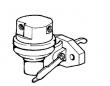
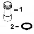
KEY PART NO. PART NAME QTY SERIAL NO. F F F REMARKS
1 R51936 SEALING WASHER 2 X
2 RE49589 FUEL LINE 1 -087549 X
RE501218 FUEL LINE 1 087550-090585 X (SUB RE504748)
RE504748 FUEL LINE 1 090586- X
R83490 FITTING 1 X
3 R76358 O-RING 1 X
4 R121195 CAP SCREW 4 X (SUB FOR R112975)
5 R121164 GEAR 1 X
6 R67364 ELBOW FITTING 1 -087549 X
RE502650 FITTING 1 087550- X
R79060 O-RING 1 087550- X
7 R114130 STUD 4 X (SUB FOR R55396, THIS APPLICATION)
8 M72490 WASHER 4 X
9 14H1090 NUT 4 X (SUB FOR R55662, THIS APPLICATION)
10 RE46252 FUEL PUMP 1 X (ROBERT BOSCH)
11 R79060 O-RING 1 X (SUB FOR R73858)
12 AR88903 ELBOW FITTING 1 X
13 R67264 PACKING 2 X
14 RE509065 OIL LINE 1 X (SUB FOR RE60577)
15 T18012 ELBOW FITTING 1 X
16 RE63767 FUEL INJECTION PUMP 1 X (A) (ROBERT BOSCH) (ALSO ORDER R64627
AND (2) 19M8826)
.. RE71255 PIPE PLUG 2 X
(A) "SEE YOUR AUTHORIZED PUMP REPAIR STATION FOR PARTS NOT LISTED"
CONSULTEZ VOTRE REPARATEUR DE POMPE AGREE POUR LES PIECES NON CATALOGUES
NICHT GEZEIGTE TEILE VON PUMPENWERKSTAT BEZIEHEN
(A) PER LE PARTI NON ELENCATE, RIVOLGETEVI AL CENTRO
CONZULTE CON SU ESTACION AUTORIZADA RE PEPARACIONES DE BOMBA.
RAADGOER MED EN AUTORISERAD PUMPSERVICVERKSTAD BETRAEFFANDE EJ UPPTAGNA
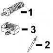
KEY PART NO. PART NAME QTY SERIAL NO. F F F REMARKS
1 R60914 SET SCREW 1 X
2 R53918 PACKING 1 X
3 T31556 NUT 1 X
4 R68715 PIN 1 X
5 AR89339 SEAL 1 X
6 AR89578 LEVER 1 X
7 24M7054 WASHER 1 X 6.400 X 12 X 1.600 MM
8 T24229 LOCK WASHER 2 X
9 R68716 NUT 1 X
10 R64627 LEVER 1 X (A)
11 19M8826 SCREW 2 X M6 X 16
12 R53976 SCREW 1 X (B)
13 24H1287 WASHER 1 X (B) 9/32" X 5/8" X 0.065"
14 R98677 LEVER 1 X (C) (LH)
15 R68438 RETAINER 1 X
16 R53955 O-RING 1 X
(A) THROTTLE (TWO HOLES AT TOP) (B) NOT INCLUDED (C) SHUT-OFF
MANETTE DES GAZ NON INCLUS ROBINET D’ARRET
DROSSELKLAPPE NICHT MIT ABSCHALTUNG
ACCELERATORE NON COMPRESO RUBINETTO D’ARRESTO
ACELERADOR NO FORMA PARTE GRIFO DECIERRE
GASREGLAGE INGAAR INTE AVSTAENGING