English
 Espaol
 Franais
 阿拉伯
阿拉伯 中文
中文 Deutsch
 Italiano
 Português
 日本
日本 韩国
韩国 български
 hrvatski
 esky
esky Dansk
Dansk Nederlands
 suomi
suomi Ελληνικ
 印度
印度 norsk
norsk Polski
 Roman
Roman русский
 Svenska
农业
1450CWS
6630
1450WTS
6830
1470
6930
1550CWS
7130
1550WTS
7230
1654
7330
1854
7430
2054
W330
6225
6525
6530


| 设备型号 | 备注 |
|---|---|
| HRYW 25 T6 | 84mm Bore Turbo |
| HYW-14 M6 | 88mm Bore Non Turbo |
| HJW 85 T6 | Piston (m) RE527039 Tier 2 & Tier 3 |
| HRYW-20 T5 | 84mm Bore Turbo |
| HYW-14 T6 | 88mm Bore Non Turbo |
| HJW 105 T6 | Piston (m) RE527039 Tier 2 & Tier 3 |
| HRYW-25 T6 | 84mm Bore Turbo |
| HYW 14 M6 | 88mm Bore Non Turbo |
| HJW 130 T6 | Piston (m) RE527039 Tier 2 & Tier 3 |
| HYW 25 M6 | 84mm Bore Turbo |
| HRYW-107 T5 | 88mm Bore Non Turbo |
| HRJW 75 T6 | Piston (m) RE527039 Tier 2 & Tier 3 |
| HYW 25 T6 | 84mm Bore Turbo |
| HRYW-20 T6 | 88mm Bore Non Turbo |
| HRJW 90 T6 | Piston (m) RE527039 Tier 2 & Tier 3 |
| HYW-20 T5 | 84mm Bore Turbo |
| HYW-17 T5 | 88mm Bore Non Turbo |
| HRJW 115 T6 | Piston (m) RE527039 Tier 2 & Tier 3 |
| HYW-25 M5 | 84mm Bore Turbo |
| HYW-20 M5 | 88mm Bore Non Turbo |
| HRJW 145 T6 | Piston (m) RE527039 Tier 2 & Tier 3 |
| HYW-25 M6 | 84mm Bore Turbo |
| HYW-20 M6 | 88mm Bore Non Turbo |
| HJW 155 T6 | Piston (m) RE527039 Tier 2 & Tier 3 |
| HYW-25 T6 | 84mm Bore Turbo |
| HYW-20 T6 | 88mm Bore Non Turbo |
| HRJW 175 T6 | Piston (m) RE527039 Tier 2 & Tier 3 |
| HYW-13 M5 | 88mm Bore Non Turbo |
| HYW 20 M6 | 88mm Bore Non Turbo |
| HJW 205 T6 | Piston (m) RE521616 Tier 2 & Tier 3 |
| HYW-13 T5 | 88mm Bore Non Turbo |
| HYW 20 T6 | 88mm Bore Non Turbo |
|
| |||||||||||||||||||||||||||
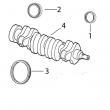
(1)1件组合式密封和穿套; 替换TRE59810,RE538097。
(2)在曲轴加工过程中必须保持正确的轴承轴颈半径,以确保正确操作。
(3)曲轴(m)R116076,直鼻。
(4)曲轴(m)R503470,锥形鼻。
(5)检查应用程序是否正确使用。
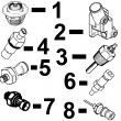
(6)线路连接都是线程化的。
(7)线路连接是一个软管倒钩& 一个线程。
(8)线路连接是两个软管倒钩。
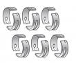
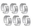
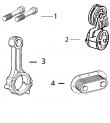
(9)机器分体式和断裂式分体式连杆均可用于同一台发动机,但每个连杆必须使用正确的连杆螺栓。