English
 Espaol
 Franais
 阿拉伯
阿拉伯 中文
中文 Deutsch
 Italiano
 Português
 日本
日本 韩国
韩国 български
 hrvatski
 esky
esky Dansk
Dansk Nederlands
 suomi
suomi Ελληνικ
 印度
印度 norsk
norsk Polski
 Roman
Roman русский
 Svenska
农业
6430
6534
7130


| 设备型号 | 备注 |
|---|---|
| 344J | Piston (m) RE527039 Tier 2 & Tier 3 |
| 644 G | High Compression Piston. To ESN 199,999. Tier 1 |
| 644 H | High Compression Piston. To ESN 199,999. Tier 1 |
| 644 J | High Compression Piston. To ESN 199,999. Tier 1 |
| 724 J | High Compression Piston. To ESN 199,999. Tier 1 |
| 244H Loader | 98mm Bore Non Turbo Direct Injection |
| 304H | 98mm Bore Non Turbo Direct Injection |
|
| ||||||||||||||||||||||||||||
约翰迪尔(John Deere) 强鹿4045D 4.5D RE59279/RE505101发动机大修包TRE66092
|
型号 |
数量 |
描述 |
|
TMX504 |
1 |
约翰迪尔(John Deere) 强鹿4045D 4.5D发动机试剂盒 (4) |
|
TR114083 |
8 |
约翰迪尔(John Deere) 强鹿4045D 4.5D发动机连杆螺钉 |
|
TR115299 |
6 |
约翰迪尔(John Deere) 强鹿4045D 4.5D发动机BUSHING, BAL SHAFT |
|
TR119874 |
1 |
约翰迪尔(John Deere) 强鹿4045D 4.5D发动机轮轴衬套 |
|
TR123960 |
4 |
约翰迪尔(John Deere) 强鹿4045D 4.5D发动机连杆衬套 PT 35 mm |
|
TRE31617 |
8 |
约翰迪尔(John Deere) 强鹿4045D 4.5D发动机气门密封 STEM LITER ENG |
|
TRE44574 |
1 |
约翰迪尔(John Deere) 强鹿4045D 4.5D发动机前油封 |
|
TRE501455 |
1 |
约翰迪尔(John Deere) 强鹿4045D 4.5D发动机大修包 |
|
TRE505515 |
1 |
约翰迪尔(John Deere) 强鹿4045D 4.5D发动机后油封 |
|
TRE65165 |
4 |
约翰迪尔(John Deere) 强鹿4045D 4.5D发动机主轴瓦(标准) |
|
TRE65168 |
1 |
约翰迪尔(John Deere) 强鹿4045D 4.5D发动机止推瓦(标准) |
|
TRE65908 |
4 |
约翰迪尔(John Deere) 强鹿4045D 4.5D发动机连杆瓦(标准 |
|
TRE65966 |
4 |
约翰迪尔(John Deere) 强鹿4045D 4.5D发动机活塞缸套四配套,包括活塞,活塞环,活塞销,缸套,卡簧,阻水圈 (RE59279) |
约翰迪尔(John Deere) 强鹿4045D 4.5D发动机TRE66092A
|
型号 |
数量 |
描述 |
|
TMX504 |
1 |
约翰迪尔(John Deere) 强鹿4045D 4.5D发动机试剂盒 (4) |
|
TR115299 |
6 |
约翰迪尔(John Deere) 强鹿4045D 4.5D发动机BUSHING, BAL SHAFT |
|
TR119874 |
1 |
约翰迪尔(John Deere) 强鹿4045D 4.5D发动机凸轮轴衬套 |
|
TR123960 |
4 |
约翰迪尔(John Deere) 强鹿4045D 4.5D发动机连杆衬套 PT 35 mm |
|
TR501124 |
8 |
约翰迪尔(John Deere) 强鹿4045D 4.5D发动机连杆螺钉 |
|
TRE31617 |
8 |
约翰迪尔(John Deere) 强鹿4045D 4.5D发动机气门密封 STEM LITER ENG |
|
TRE44574 |
1 |
约翰迪尔(John Deere) 强鹿4045D 4.5D发动机前油封 |
|
TRE501455 |
1 |
约翰迪尔(John Deere) 强鹿4045D 4.5D发动机大修包 |
|
TRE505515 |
1 |
约翰迪尔(John Deere) 强鹿4045D 4.5D发动机后油封 |
|
TRE65165 |
4 |
约翰迪尔(John Deere) 强鹿4045D 4.5D发动机主轴瓦(标准) |
|
TRE65168 |
1 |
约翰迪尔(John Deere) 强鹿4045D 4.5D发动机止推瓦(标准) |
|
TRE65908 |
4 |
约翰迪尔(John Deere) 强鹿4045D 4.5D发动机连杆瓦(标准 |
|
TRE65966 |
4 |
约翰迪尔(John Deere) 强鹿4045D 4.5D发动机活塞缸套四配套,包括活塞,活塞环,活塞销,缸套,卡簧,阻水圈 (RE59279) |
约翰迪尔(John Deere) 强鹿4045D 4.5D发动机内部修理套件TIK66092
|
型号 |
数量 |
描述 |
|
TR114083 |
8 |
约翰迪尔(John Deere) 强鹿4045D 4.5D发动机连杆螺钉 |
|
TR123352 |
1 |
约翰迪尔(John Deere) 强鹿4045D 4.5D发动机GASKET, OIL PAN |
|
TR97342 |
1 |
约翰迪尔(John Deere) 强鹿4045D 4.5D发动机GASKET, OIL PAN 4 CYL |
|
TRE31617 |
8 |
约翰迪尔(John Deere) 强鹿4045D 4.5D发动机气门密封 STEM LITER ENG |
|
TRE65165 |
4 |
约翰迪尔(John Deere) 强鹿4045D 4.5D发动机主轴瓦(标准) |
|
TRE65168 |
1 |
约翰迪尔(John Deere) 强鹿4045D 4.5D发动机止推瓦(标准) |
|
TRE65908 |
4 |
约翰迪尔(John Deere) 强鹿4045D 4.5D发动机连杆瓦(标准 |
|
TRE65966 |
4 |
约翰迪尔(John Deere) 强鹿4045D 4.5D发动机活塞缸套四配套,包括活塞,活塞环,活塞销,缸套,卡簧,阻水圈 (RE59279) |
|
TRE66082 |
1 |
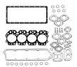
约翰迪尔(John Deere) 强鹿4045D 4.5D发动机GASKET, CYL HEAD SET P.T. |
约翰迪尔(John Deere) 强鹿4045D 4.5D发动机TIK66092A
|
型号 |
数量 |
描述 |
|
TR123352 |
1 |
约翰迪尔(John Deere) 强鹿4045D 4.5D发动机GASKET, OIL PAN P.T. |
|
TR501124 |
8 |
约翰迪尔(John Deere) 强鹿4045D 4.5D发动机连杆螺钉 |
|
TR97342 |
1 |
约翰迪尔(John Deere) 强鹿4045D 4.5D发动机GASKET, OIL PAN 4 CYL |
|
TRE31617 |
8 |
约翰迪尔(John Deere) 强鹿4045D 4.5D发动机气门密封 STEM LITER ENG |
|
TRE65165 |
4 |
约翰迪尔(John Deere) 强鹿4045D 4.5D发动机主轴瓦(标准) |
|
TRE65168 |
1 |
约翰迪尔(John Deere) 强鹿4045D 4.5D发动机止推瓦(标准) |
|
TRE65908 |
4 |
约翰迪尔(John Deere) 强鹿4045D 4.5D发动机连杆瓦(标准 |
|
TRE65966 |
4 |
约翰迪尔(John Deere) 强鹿4045D 4.5D发动机活塞缸套四配套,包括活塞,活塞环,活塞销,缸套,卡簧,阻水圈 (RE59279) |
|
TRE66082 |
1 |
约翰迪尔(John Deere) 强鹿4045D 4.5D发动机GASKET, CYL HEAD SET P.T. |
(1)1件组合式密封和穿套; 替换TRE59810,RE538097。
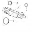
(2)在曲轴加工过程中必须保持正确的轴承轴颈半径,以确保正确操作。
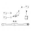
(3)锥形鼻子。
(4)直鼻。
(5)检查应用程序是否正确使用。
(6)线路连接都是线程化的。
(7)线路连接是一个软管倒钩& 一个线程。
(8)线路连接是两个软管倒钩。
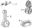
(9)机器分体式和断裂式分体式连杆均可用于同一台发动机,但每个连杆必须使用正确的连杆螺栓。
美国约翰.迪尔(强鹿)JOHNDEERE纯正配件。P550758、P550020、P550595、P558329、P550351、P551421、P551423、P556745、P551428、P551422、P551435、P551434、P550192、P550397、P551352、P181054、P77868、P777869、P550667、P550779disconnected 3. using a multimeter, measure resistance between terminals c&d in the harness end of the diagnostic connector. between 45 - 75 ohms: go to 8 less than 45/greater than 75 ohms: faulty/missing can terminator connector(s) or open/short in can wiring harness 04 150 37 – – –1/1 8 can high&low voltage test note: for wiring information, see d1 - ecu does not communicate with dst supporting information. 1. ignition off 2. reconnect ecu 60-way connector 3. ignition on 4. using a multimeter, measure voltage between a good chassis ground and: ? terminal c in the diagnostic connector ? terminal d in the diagnostic connector both measurements between 1.5 - 3.5 v: faulty ecu connection or faulty diagnostic cable or faulty diagnostic connector or faulty parallel port data module (pdm) or faulty diagnostic software/computer configuration or faulty ecu either measurement less than 1.5 v or greater than 2.5 v: can wiring shorted to ground/voltage or faulty ecu ctm188 (20mar01) 04-150-37 powertech 10.5 l & 12.5 l level 6 fuel system 032001 pn=179 observable diagnostics&tests 04 150 38 rg40854,000005c –19–11jan01–1/1 level 6 ecu - d2 - ecu does not communicate with diagnostic gauge rg11650 –19–23jan01 important: do not force probes into connector terminals/damage will result. use the jt07328 connector adapter test kit to make measurements in connectors. this will ensure that terminal damage does not occur. internal diagnostic gauge errors ? the d2 - ecu does not communicate with diagnostic gauge diagnostic procedure should be followed if the diagnostic gauge shows the following error codes/it can not communicate with the ecu: – ee-error – acp-err/no addr – acp-err/bus ep – acp-err/bus error ctm188 (20mar01) 04-150-38 powertech 10.5 l & 12.5 l level 6 fuel system 032001 pn=180 observable diagnostics&tests rg40854,000005d –19–12jan01–1/1 level 6 ecu - d2 - ecu does not communicate with diagnostic gauge - continued – – –1/1 level 6 ecu - d2 - diagnostic gauge does not communicate with ecu note: before using this diagnostic procedure, perform a preliminary inspection of the 60-way ecu connector and the diagnostic gauge connector looking for dirty, damaged,/poorly positioned terminals. 04 150 39 – – –1/1 1 intermittent fault test note: for wiring information, see d2 - ecu does not communicate with diagnostic gauge supporting information. 1. ignition off 2. ignition on error/no power found in diagnostic gauge: go to 2 no error found and power present in diagnostic gauge: problem is intermittent. if no other codes are present, see intermittent fault diagnostics, in group 160. – – –1/1 2 sen*** voltage test note: for wiring information, see d2 - ecu does not communicate with diagnostic gauge supporting information. 1. ignition off 2. disconnect any of the following: ? fuel temperature sen*** ? mat sen*** ? ect sen*** 3. ignition on. 4. using a multimeter, measure the voltage between both terminals of the selected sen*** harness connector. 3.0 v/above: go to 4 below 3.0 v: go to 3 ctm188 (20mar01) 04-150-39 powertech 10.5 l & 12.5 l level 6 fuel system 032001 pn=181 observable diagnostics&tests – – –1/1 3 power supply test note: for wiring information, see d2 - ecu does not communicate with diagnostic gauge supporting information. 1. ignition off 2. disconnect 48-way ecu connector 3. ignition on 4. using a multimeter, measure the voltage between a good ground&terminal g1 in the harness end of the 30 terminal half of the 48-way ecu connector. 3.0 v/above: faulty ecu power fuse or faulty ecu power wiring or faulty ecu below 3.0 v: key-on signal wire open or shorted to ground or faulty ignition switch or faulty key-on power fuse 04 150 40 – – –1/1 4 diagnostic gauge power test note: for wiring information, see d2 - ecu does not communicate with diagnostic gauge supporting information. 1. ignition on 2. view diagnostic gauge gauge has power: go to 6 gauge does not have power: go to 5 – – –1/1 5 open in diagnostic connector ground wire test note: for wiring information, see d2 - ecu does not communicate with diagnostic gauge supporting information. 1. ignition off 2. disconnect the diagnostic cable from the diagnostic connector 3. probe terminal d in the diagnostic gauge connector with a test light connected to battery voltage. light on: open/short to ground in diagnostic gauge switched power wire. light off: open in diagnostic connector ground wire. – – –1/1 6 open in harness circuit test note: for wiring information, see d2 - ecu does not communicate with diagnostic gauge supporting information. 1. ignition off 2. disconnect 60-way ecu connector&diagnostic cable from the diagnostic connector 3. using a multimeter, measure resistance on the harness end of both connectors between: ? terminal b in the diagnostic gauge connector&terminal b1 in the 60-way ecu connector ? terminal g in the diagnostic gauge connector&terminal b2 in the 60-way ecu connector all measurements 5 ohms/less: go to 7 one/more measurements greater than 5 ohms: open in harness circuit or connector terminals in wrong position ctm188 (20mar01) 04-150-40 powertech 10.5 l & 12.5 l level 6 fuel system 032001 pn=182 observable diagnostics&tests – – –1/1 7 can resistance test note: for wiring information, see d2 - ecu does not communicate with diagnostic gauge supporting information. 1. ignition off 2. 60-way ecu&diagnostic connector still disconnected 3. using a multimeter, measure resistance between terminals b&g in the harness end of the diagnostic connector. between 45 - 75 ohms: go to 8 less than 45/greater than 75 ohms: faulty/missing can terminator connector(s) or open/short in can wiring harness 04 150 41 – – –1/1 8 can high&low voltage test note: for wiring information, see d2 - ecu does not communicate with diagnostic gauge supporting information. 1. ignition off 2. reconnect ecu 60-way connector 3. ignition on 4. using a multimeter, measure voltage between a good chassis ground and: ? terminal b in the diagnostic gauge connector ? terminal g in the diagnostic gauge connector both measurements between 1.5 - 3.5 v: faulty ecu connection or faulty diagnostic gauge connector or faulty diagnostic software/computer configuration or faulty ecu either measurement less than 1.5 v or greater than 2.5 v: can wiring shorted to ground/voltage or faulty ecu ctm188 (20mar01) 04-150-41 powertech 10.5 l & 12.5 l level 6 fuel system 032001 pn=183 observable diagnostics&tests 04 150 42 dpsg,rg40854,355 –19–07oct99–1/1 check dual rail fuel supply pressure rg10662 –un–14dec99 checking fuel supply pressure a—fuel supply pressure quick connect port 1. connect a 0-1000 kpa (0-150 psi) gauge to the diagnostic quick-connect on the air purge valve after removing the dust cap&cleaning the quick-disconnect. 2. open bleed valve 3. start/crank engine. fuel transfer pump should maintain minimum pressure shown in specification. specification fuel transfer pump pressure— cranking (minimum 200 rpm) 70–170 kpa (0.7–1.7 bar) (15–25 psi) . normal (idle) 410–480 kpa (4.1–4.8 bar) (60– 70 psi) . rated speed 620–690 kpa (6.2–6.9 bar) (90– 100 psi) ctm188 (20mar01) 04-150-42 powertech 10.5 l & 12.5 l level 6 fuel system 032001 pn=184 observable diagnostics&tests 04 150 43 rg,rg34710,1551 –19–30sep97–1/1 bleed dual rail fuel system rg8714b –un–21nov97 draining water separator rg8725 –un–05dec97 bleeding fuel system rg10250 –un–30jul99 air purge valve whenever the fuel system has been opened up for service (lines disconnected/filters removed), it will be necessary to bleed air from the system. 1. drain water&contaminants from clear water separator sediment bowl (c) by opening drain valve (a), then operate hand primer (b) until bowl is clear of water&debris. 2. loosen secondary (final) fuel filter outlet line (a) or remove cap&open air purge valve (d), (if equipped). 3. pump hand primer (b) on primary filter until a steady flow of fuel (without bubbles) comes out of connection. 4. continue pumping hand primer&simultaneously tighten outlet line connection to 24 n?m (18 lb-ft). do not overtighten. 5. start engine&run at high idle for 3–5 minutes. note: if both filters were replaced, hand priming will purge air form the secondary filter followed by clean fuel, followed by air from the primary filter. failure to bleed air from both filters will cause the engine to die due to air trapped in the system ctm188 (20mar01) 04-150-43 powertech 10.5 l & 12.5 l level 6 fuel system 032001 pn=185 observable diagnostics&tests 04 150 44 dpsg,rg40854,355 –19–07oct99–1/1 check single rail fuel supply pressure rg10661 –un–14dec99 checking fuel supply pressure a—fuel supply pressure quick connect port 1. connect a 0-1000 kpa (0-150 psi) gauge to the diagnostic quick-connect on the air purge valve after removing the dust cap&cleaning the quick-disconnect. 2. open bleed valve 3. start/crank engine. fuel transfer pump should maintain minimum pressure shown in specification. specification fuel transfer pump pressure— cranking (minimum 200 rpm) 135–175 kpa (1.35–1.75 bar) (20–25 psi) normal (idle) 410–555 kpa (4.1–5.5 bar) (60– 80 psi) . rated speed 480–620 kpa (4.8–6.2 bar) (70– 90 psi) ctm188 (20mar01) 04-150-44 powertech 10.5 l & 12.5 l level 6 fuel system 032001 pn=186 observable diagnostics&tests 红河强鹿柴油机机油泵厂家供应,临沧JohnDeere排气门R520224公司,曲靖强鹿6090柴油发动机风扇张紧轮找哪家,广安强鹿柴油机4045主轴瓦批发商,宁德约翰迪尔强鹿柴油机连杆螺丝信息,清远约翰迪尔4045柴油机张紧轮厂家供应,重庆美国JohnDeere发电机皮带R135193多少钱,包头强鹿节恒温器供应商,东营约翰迪尔强鹿水泵RE530194诚信推荐,凉山强鹿油泵RE66153厂家价格,许昌约翰迪尔多功能拖拉机发动机配件供应商,松原约翰迪尔发动机连杆铜套厂家价格,洛阳约翰迪尔5-1000拖拉机发动机配件哪家买,大兴安岭约翰迪尔充电发电机RE506197一级代理,绍兴约翰迪尔3029柴油发动机滤清器RE60021价格行情,沈阳约翰.迪尔滤清器RE59754供货商,朝阳JOHNDEERE强鹿6125HF070B配件供应商,鄂尔多斯强鹿机滤RE58935诚信推荐,柳州约翰迪尔柴油机水温传感器el52222批发商,辽阳约翰迪尔柴油机RE55343凸轮轴衬套多少钱,赤峰johndeere约翰迪尔强鹿柴油发动机起动机RE70960信息,随州强鹿连杆铜套R74008公司,驻马店约翰迪尔柴油发电机组活塞销代理商,德宏约翰迪尔3029DF128机油泵供应商,昆明约翰迪尔re525523强鹿柴油滤芯价格行情,桂林强鹿6081发动机主轴瓦市场报价,萍乡johndeere约翰迪尔强鹿柴油发动机启动马达RE523502供货商,宝鸡强鹿进气门RE531221厂家供货,铁岭强鹿柴油机泵芯多少钱,十堰6081强鹿johndeere约翰迪尔发电机配件价格,陇南JohnDeere加大连杆瓦RE65909代理,阳泉约翰迪尔机油滤芯RE57394价格,朔州强鹿传感器RE522794诚信推荐,来宾直销美国强鹿柴油机配件诚信推荐,宝鸡美国强鹿4045TF258发动机维修保养配件市场报价,盘锦强鹿柴油发动机水温传感器找哪家,楚雄约翰迪尔拖拉机发动机电磁阀哪里买,吐鲁番johndeere约翰迪尔强鹿输油泵哪家好,邯郸JOHNDEERE喷油器代理,鄂尔多斯强鹿滤芯滤清器RE51629哪家好,呼和浩特约翰迪尔机油滤清器RE504836市场报价,九龙约翰迪尔强鹿3029曲轴位置传感器供应商,张掖约翰迪尔4039DF008柴油机配件供货商,台湾强鹿柴油发电机组曲轴厂家批发,泰安约翰迪尔CH530甘蔗收获机发动机配件哪家买,黔南约翰迪尔活塞RE30250哪家买,辽阳约翰迪尔缸套活塞组件RE507850哪家好,绥化约翰迪尔挖掘机缸套市场报价,三亚强鹿柴油机燃油泵RE533095的价格,商洛约翰迪尔曲轴RE505921供应商,丽水约翰迪尔4039连杆R80032代理,嘉兴JohnDeere凸轮轴铜套TR119874一级代理,黄山约翰迪尔强鹿4045柴油机止推轴承RE65912厂家供货,赣州强鹿约翰迪尔喷油器SE501957批发价,广州强鹿柴油发电机组缸套哪家好,日喀则强鹿柴油滤芯P550135价格行情,乐山约翰迪尔发动机机油泵代理,蚌埠JohnDeere后油封RE530121供应商,兴安约翰迪尔柴油发动机机油滤清器信息,东营约翰迪尔气缸垫R116516供货商,吕梁约翰迪尔挖掘机进排气门厂家价格,遂宁强鹿空气压力传感器RE61812批发价,白银强鹿气门弹簧R502187市场报价,大庆强鹿水泵RE546918厂家批发,重庆JOHNDEERE约翰迪尔柴油发电机配件批发商,陇南JohnDeere加大连杆瓦RE65909一级代理,嘉峪关约翰迪尔连杆瓦RE65908厂家批发,04 150 45 dpsg,rg40854,356 –19–07oct99–1/1 bleed single rail fuel system rg10309 –un–02sep99 bleed fuel system a—diagnostic port b—hand primer c—water drain valve note: under normal conditions, fuel system bleeding is not required. priming system with hand primer (b) is normally sufficient. if necessary to bleed the system, use the following procedure. 1. drain water&contaminates from clear water separator sediment bowl by opening drain valve (c) and operating primer (b) until bowl is clear of water. 2. attach an open line to diagnostic port (a)&place end of line in suitable container for diesel fuel. 3. pump hand primer (b) until a steady flow of fuel (without bubbles) comes out of line. note: it can take up to 200 strokes until fuel comes out steadily. 4. disconnect line from diagnostic port (a). 5. pump hand primer (b). note: if engine has been run out of fuel, 200 strokes will be necessary. 6. start engine&run for five minutes. note: if engine does not start after 20 seconds of cranking, pump hand primer an additional 100 strokes,&attempt to start engine again. ctm188 (20mar01) 04-150-45 powertech 10.5 l & 12.5 l level 6 fuel system 032001 pn=187 observable diagnostics&tests 04 150 46 ctm188 (20mar01) 04-150-46 powertech 10.5 l & 12.5 l level 6 fuel system 032001 pn=188 group 160 trouble code diagnostics&tests 04 160 1 rg,rg34710,1552 –19–20dec00–1/1 about this group of the manual this group of the manual contains necessary information to diagnose the electronic control system. use this information in conjunction with the 10.5 l & 12.5 l diesel engines base engine (ctm100). see the 10.5 l&12.5 l diesel engines base engine manual for: ? removal of base engine components ? base engine repair procedures ? base engine disassembly ? base engine inspection ? base engine assembly ? base engine diagnostics&tests parts such as sen***s, actuators, connectors, and wiring harnesses are serviceable&available. important: not under any circumstances, should the engine control unit (ecu) be opened. note: instruction is given throughout the diagnostic charts to make resistance&voltage measurements in the ecu/cab connector and the ecu/engine connector. note that these measurements are always made in the harness end of the connector. measurements should never be made in the ecu end of the connection. rg,rg34710,1553 –19–30sep97–1/1 electrical concepts tests will include making measurements of voltage and resistance&making checks for open circuits&short circuits. an understanding of the following concepts is required to use the diagnostic procedures: ? voltage (volts) ? current (amps) ? resistance (ohms) ? open circuit ? short circuit ctm188 (20mar01) 04-160-1 powertech 10.5 l & 12.5 l level 6 fuel system 032001 pn=189 trouble code diagnostics&tests 04 160 2 dpsg,rg40854,37 –19–15dec98–1/6 electrical circuit malfunctions circuit malfunctions there are four major circuit malfunctions. they are: 1. high-resistance circuit 2. open circuit 3. grounded circuit 4. shorted circuit dpsg,rg40854,37 –19–15dec98–2/6 rg9891 –un–06jan99 high resistance circuit a—unwanted resistance definition of circuit malfunctions 1. high resistance circuit: a circuit having unwanted resistance (a) that causes a voltage drop&reduces current flow. dpsg,rg40854,37 –19–15dec98–3/6 rg9892 –un–06jan99 open circuit a—break/separation in circuit 2. open circuit: a circuit having a break/a separation (a) that prevents current from flowing in the circuit. ctm188 (20mar01) 04-160-2 powertech 10.5 l & 12.5 l level 6 fuel system 032001 pn=190 continued on next page trouble code diagnostics&tests 04 160 3 dpsg,rg40854,37 –19–15dec98–4/6 rg9893 –un–06jan99 grounded circuit a—voltage wire in contact with machine frame 3. grounded circuit: a voltage wire in contact with the machine frame (a), providing continuity with the battery ground terminal. dpsg,rg40854,37 –19–15dec98–5/6 rg9894 –un–06jan99 shorted circuit 4. shorted circuit: a wire-to-wire contact of two adjacent wires that provides unwanted continuity between the two wires. the following are types of short circuits: ? voltage wire shorted to another voltage wire (wires of equal/unequal voltage). ? voltage wire shorted to a sen*** signal wire (wires of unequal voltage). ? voltage wire shorted to a ground wire (wires of battery voltage/regulated voltage, shorted to a ground wire connecting a component to the battery negative terminal). ? ground wire shorted to another ground wire (wires of zero voltage). note: this type of short does not create an observable malfunction. therefore, no further explanation for trouble shooting is necessary. continued on next page ctm188 (20mar01) 04-160-3 powertech 10.5 l & 12.5 l level 6 fuel system 032001 pn=191 trouble code diagnostics&tests 04 160 4 dpsg,rg40854,37 –19–15dec98–6/6 rg9895 –un–06jan99 locations of circuit malfunctions a—controlling switch b—load locations of circuit malfunctions: in a “simple electrical circuit” the circuit malfunctions occur at only three locations. they are: 1. before the controlling switch (a). 2. between the controlling switch (a)&the load (b). 3. after the load (b). electrical components can become faulty with the same four circuit malfunctions. sometimes component malfunctions can easily be confused with circuit malfunctions. therefore, care must be exercised when isolating the cause of the problem. example: a component may not operate before disconnecting an electrical connection, but it operates after reconnecting the connector. reason: oxidation of the terminals created “high resistance”&a voltage drop that prevents the proper amount of current flow to the component. disconnecting&reconnecting the connector, removed some oxidation&re-established good continuity through the connector. ctm188 (20mar01) 04-160-4 powertech 10.5 l & 12.5 l level 6 fuel system 032001 pn=192 trouble code diagnostics&tests 04 160 5 dpsg,rg40854,38 –19–15dec98–1/4 troubleshooting circuit malfunctions rg9896 –un–06jan99 troubleshooting circuit malfunctions a—battery d—unwanted resistance g—circuit connector i—load (lamp) b—switch e—circuit connector h—component terminal j—ground c—component terminal f—open circuit 1. high resistance circuit: a “high resistance” circuit can result in slow, dim or no component operation (for example: loose, corroded, dirty/oily terminals, gauge of wire too small/broken strands of wire). 2. open circuit: an “open” circuit results in no component operation because the circuit is incomplete (for example: broken wire, terminals disconnected, open protective device/open switch). do the following to isolate the location of a “high resistance”/“open” circuit: a. with the controlling switch (b) closed (on) and the load (i) connected into the circuit, check for proper voltage at a location easily accessible between (c)&(h). ? if voltage is low, move toward the voltage source (a) to locate the point of voltage drop. ? if voltage is correct, move toward the load (i) and ground terminal (j) to locate the voltage drop. note: the example shows high resistance (d) between (c)&(e)&the open circuit (f) between (e)&(g). b. repair the circuit as required. c. perform an operational check-out on the component after completing the repair. continued on next page ctm188 (20mar01) 04-160-5 powertech 10.5 l & 12.5 l level 6 fuel system 032001 pn=193 trouble code diagnostics&tests 04 160 6 dpsg,rg40854,38 –19–15dec98–2/4 rg9897 –un–06jan99 ground circuit a—fuse “a” terminal c—switch e—wire terminal g—component terminal b—fuse “b” terminal d—component terminal f—grounded circuit h—load (lamp) 3. ground circuit: a “grounded” circuit (f) results in no component operation&the fuse/circuit breaker opens (for example: a power wire contacting the machine frame, chassis/component housing). do the following to isolate the location of a “grounded” circuit: a. switch (c) must be open (off). check for continuity to ground between (b)&(c). ? if there is continuity, there is a grounded circuit between (b)&(c). repair the circuit. ? no continuity, go to step b. b. disconnect the load (h) at component terminal (g). c. with the controlling switch (c) open (off), check for continuity to ground between (d)&(e). ? if there is continuity, there is a grounded circuit between (d)&(e). repair the circuit. note: the example is grounded between (d)&(e) at (f). ? perform an operational check-out on the component after completing the repair. continued on next page ctm188 (20mar01) 04-160-6 powertech 10.5 l & 12.5 l level 6 fuel system 032001 pn=194 trouble code diagnostics&tests 04 160 7 dpsg,rg40854,38 –19–15dec98–3/4 control unit 5v (+) sen*** 5v (-) battery sw.2 e2 f2 f3 d e h i f1 a sw.1 b c e1 f g a b c signal rg11399 –un–29nov00 shorted circuit 4. shorted circuit: machines equipped with several electronic control devices contain wiring harnesses that can become shorted by one of the following ways shown above. 1. battery wire from fuse (f1) is shorted at (a) to another battery wire after switch (sw.2). ? result: lamp (e1) is on all of the time. 2. battery wire from fuse (f1) is shorted at (b) to another battery wire after switches (sw.1 & 2). ? result: both lamps (e1 & e2) operate on either switch (sw. 1/2). 3. battery wire from fuse (f1) is shorted at (c) to a ground wire. ? result: fuse (f1) opens after closing switch (sw. 1) 4. battery wire from switch (sw. 2) is shorted at (d) to a regulated volt, age wire. ? result: the sen*** signal voltage is distorted.1 5. battery wire from switch (sw. 2) is shorted at (e) to the sen*** signal voltage wire. ? result: the sen*** signal is distorted.1 6. battery wire from switch (sw. 2) is shorted at (f) to the sen*** ground wire. ? result: fuse (f2) opens after closing switch (sw. 2)&the sen*** signal is distorted.1 7. controller regulated voltage wire is shorted at (g) to the sen*** signal voltage wire. ? result: the sen*** signal is distorted. 8. controller regulated voltage wire is shorted at (h) to the sen*** ground wire. ? result: the sen*** signal is distorted.1 9. sen*** voltage wire is shorted at (i) to the sen*** ground wire. ? result: the sen*** signal is distorted.1 do the following to isolate a “shorted circuit:” a. review the machine electrical schematic to identify the circuits for the component that does not operate. b. disconnect the components at each end of the circuits, to single out the affected wires. c. to prevent damage to connector terminals, obtain mating connector terminals from repair parts. do not force meter probes into connector terminals. 1the sen*** signal voltage goes out of range&a fault code may be restored. the controller may shut down/provide limited operation for its function. ctm188 (20mar01) 04-160-7 powertech 10.5 l & 12.5 l level 6 fuel system 032001 pn=195 continued on next page trouble code diagnostics&tests 04 160 8 dpsg,rg40854,38 –19–15dec98–4/4 d. connect the meter leads across two of the affected circuits. the meter should show no continuity between the two circuits. repeat the check across another combination of two circuits until all affected circuits have been checked. e. then, connect a meter lead to each affected circuit one at a time&touch the other meter leads to all terminals in the connector. the meter should show no continuity between any two circuits. example: a 37 pin connector contains three wires to a sen***. with one meter probe attached to each of the three wires, one at a time, touch the other meter probe to the remaining 36 wires. if there is continuity between any two wires, the circuit is shorted. repair the circuit. f. alternate method to check for shorted circuit. with the components disconnected at each end of the suspected circuits, turn the key switch on. connect one meter lead to a good frame ground. with the other meter probe, touch each of the suspected circuits one at a time. if there is a voltage reading, the circuit is shorted to another voltage wire. repair the circuit. g. repair the “shorted circuit” as follows: ? wires not in a loom: wrap individual wires with electrical tape/replace the damaged wire and band as required. ? wires in a loom: if hot spots exist in shorted area of the harness, replace the harness. if hot sports are not noticeable, install a new wire of proper gauge between the last two connections. use tie bands to secure the wire to outside of the harness. h. perform an operational check-out on the component after completing the repair. ctm188 (20mar01) 04-160-8 powertech 10.5 l & 12.5 l level 6 fuel system 032001 pn=196 trouble code diagnostics&tests 04 160 9 rg,rg34710,1554 –19–30sep97–1/1 using a digital multimeter rg11126 –un–19jun00 digital multimeter it is recommended that a digital multimeter (jt07306 or equivalent with an analog display) be used to make the required measurements in the diagnostic procedures. a knowledge of the operation of the particular meter used is assumed. instructions for measuring voltages take the following form: ? measure voltage from point a (+) to point (b) (-) in this example, the positive test lead from the volt-ohm input of the meter should be connected to point a&the negative test lead from the common input of the meter should be connected to point b. unless otherwise stated, all voltage measurements are direct current (d.c.). in making a resistance measurement, be careful to use the correct resistance range on the meter. disconnect appropriate connectors/turn off key switch, as directed by diagnostic procedures later in this group. ctm188 (20mar01) 04-160-9 powertech 10.5 l & 12.5 l level 6 fuel system 032001 pn=197 trouble code diagnostics&tests 04 160 10 dpsg,ouod007,2842 –19–21oct99–1/2 engine configuration data parameters on diagnostic gauge rg11647 –19–19jan01 engine configuration map rg10031 –un–28oct99 diagnostic gauge a—diagnostic gauge b—touch switches c—lights accessing engine configuration data parameters: 1. scroll through the main menu of engine parameters by pressing either the right/the left touch switch 2. select “e-config” sub-menu by simultaneously pressing the right&the left touch switch. 3. scroll through the “e-config”sub-menu to view engine configuration parameters by pressing either the right or the left touch switch until desired parameter is found. the numbers next to the parameters correspond to the number on the graph. 4. in order to exit “e-config” sub-menu, simultaneously press the right&left touch switch continued on next page ctm188 (20mar01) 04-160-10 powertech 10.5 l & 12.5 l level 6 fuel system 032001 pn=198 trouble code diagnostics&tests 04 160 11 dpsg,ouod007,2842 –19–21oct99–2/2 engine configuration parameter description parameter displayed on units description diagnostic gauge speed 1 rpm stationary low idle speed of engine which includes influences due to engine temperature&other stationary changes. this is point 1 on the engine configuration map. torque 1 % torque 1 equals the desired torque of the ecu divided by the reference torque. speed 2 rpm engine speed at point 2 of the engine configuration map. this is defined as the kick-in point for which torque is reduced to zero. torque 2 % torque 2 equals the desired torque of the ecu divided by the reference torque. speed 3 rpm engine speed at point 3 of the engine configuration map. points 3, 4,&5 are optional&can be located anywhere between points 1&2. torque 3 % torque 3 equals the desired torque of the ecu divided by the reference torque. speed 4 rpm engine speed at point 4 of the engine configuration map. points 3, 4,&5 are optional&can be located anywhere between points 1&2. torque 4 % torque 4 equals the desired torque of the ecu divided by the reference torque. speed 5 rpm engine speed at point 5 of the configuration map. points 3, 4,&5 are optional and can be located anywhere between points 1&2. torque 5 % torque 5 equals the desired torque of the ecu divided by the reference torque. speed 6 rpm engine speed of high idle. torque 6 % torque 6 equals the desired torque of the ecu divided by the reference torque. gov gain % equals the change of torque between points 2&6 divided by the change of engine speed between points 2&6. ref torque nm (ft-lbs) this parameter is the 100% reference value for all defined indicated engine torque parameters. it is only defined once&doesn’t change if a different engine torque map becomes valid. speed 7 rpm the maximum engine speed above point 6 allowed by the engine control during a momentary high idle override. this duration is limited by the maximum momentary override time limit. time limit sec the maximum time limit allowed to override the engine’s high idle speed. lo limit rpm the minimum engine speed that the engine will allow when operating in a speed control/limit mode hi limit rpm the maximum engine speed that the engine will allow when operating in a speed control/limit mode. low limit % the minimum engine torque that the engine will allow when operating in a torque control/limit mode. hi limit % the maximum engine torque that the engine will allow when operating in a torque control/limit mode. ctm188 (20mar01) 04-160-11 powertech 10.5 l & 12.5 l level 6 fuel system 032001 pn=199 trouble code diagnostics&tests 04 160 12 dpsg,ouod007,2842 –19–15nov00–1/1 viewing active dtcs on diagnostic gauge rg10031 –un–28oct99 a—diagnostic gauge b—touch switches c—lights accessing active diagnostic trouble codes (dtcs): 1. scroll through the main menu of engine parameters by pressing either the right/the left touch switch 2. select “srvccodes” sub-menu by simultaneously pressing the right&the left touch switch. 3. scroll through the “srvc codes ”sub-menu to view active dtcs by pressing either the right/the left touch switch until all codes are found. 4. in order to exit “srvccodes” sub menu, simultaneously press the right&left touch switch dpsg,ouod007,2842 –19–21oct99–1/1 viewing stored dtcs on diagnostic gauge rg10031 –un–28oct99 a—diagnostic gauge b—touch switches c—lights accessing stored diagnostic trouble codes (dtcs): 1. scroll through the main menu of engine parameters by pressing either the right/the left touch switch 2. select “dm2codes” sub-menu by simultaneously pressing the right&the left touch switch. 3. scroll through the “dm2codes”sub-menu to view stored dtcs by pressing either the right/the left touch switch until all codes are found. note: if “no data” is on the gauge, there are no stored codes. 4. in order to exit “dm2codes” sub menu, simultaneously press the right&left touch switch ctm188 (20mar01) 04-160-12 powertech 10.5 l & 12.5 l level 6 fuel system 032001 pn=200 trouble code diagnostics&tests 04 160 13 rg40854,000006a –19–23jan01–1/1 clearing stored dtcs on diagnostic gauge rg10031 –un–28oct99 a—diagnostic gauge b—touch switches c—lights clearing stored diagnostic trouble codes (dtcs): 1. scroll through the main menu of engine parameters by pressing either the right/the left touch switch 2. select “dm2codes” sub-menu by simultaneously pressing the right&the left touch switch. 3. scroll through the “dm2codes”sub-menu to view stored dtcs by pressing either the right/the left touch switch until all codes are found. note: if “no data” is on the gauge, there are no stored codes. 4. in order to clear codes, simultaneously press the right and left switch for at least 8 seconds note: if the switches are held for less than 8 seconds, the sub menu will be exited. 5. press the right switch for at least 8 seconds. note: if the switch is held for less than 8 seconds, the sub menu will be exited. 6. codes are now cleared. in order to exit “dm2codes” sub menu, simultaneously press the right&left touch switch ctm188 (20mar01) 04-160-13 powertech 10.5 l & 12.5 l level 6 fuel system 032001 pn=201 trouble code diagnostics&tests 04 160 14 rg,rg34710,1560 –19–21nov00–1/2 data parameter de, scription following is a list of the data parameters that can be read on the diagnostic scan tool (dst). the dst consists of a windows (’95, ’98/2000)/nt compatible computer, jdis121 - ecu communication hardware kit, and jdis122 - ecu communication software kit, available from john deere. included in the list below is a brief description of each parameter, the range of possible readings,&each parameter’s unit of measurement. parameter units description engine hour meter hr total hours the ecu has run on an engine. -min- sec battery voltage volts battery volts on most applications can be either 12/24 volts. engine speed rpm the speed that the crank sen*** detects the crank timing wheel to be moving at. crank position sen*** speed rpm the speed of the crank timing wheel. the speed of the crank timing wheel should be 2x’s the speed, of the cam timing wheel. crank position status naa when status is 15, the ecu is receiving all of the signal. when the status is below 15, it means that the ecu is not receiving all of the signal. crank position noise indicator % a "0" reading means that there is no noise. between 0—100, crank noise becomes progressively worse. when 100 is reached, a trouble code is thrown. crank improper pattern % a "0" reading means that there is no improper pattern. between 0—100, the crank pattern indicator becomes progressively more improper. when 100 is reached, a trouble code is thrown. cam position sen*** speed rpm the speed of the cam timing wheel. the speed of the cam timing wheel should be 1/2 the speed of the crank timing wheel. cam position status naa when status is 15, the ecu is receiving all of the signal. when the status is below 15, it means that the ecu is not receiving all of the signal. cam position input noise % a "0" reading means that there is no noise. between 0—100, cam noise becomes indicator progressively worse. when 100 is reached, a trouble code is thrown. cam improper pattern indicator % a "0" reading means that there is no improper pattern. between 0—100, the cam pattern becomes progressively more improper. when 100 is reached, a trouble code is thrown. engine coolant temperature °c engine coolant temperature value. (°f) note: if there is an active fault for the ect circuit, the ect value displayed will be the “limp-home” value. sen*** supply voltage volts voltage the ecu supplies to sen***s. typically, this value is 5 volts. engine coolant temperature volts engine coolant temperature sen*** input voltage to the ecu input voltage fuel pressure kpa (psi) on single rail fuel system applications, the ecu monitors fuel pressure. fuel pressure input voltage volts the input voltage from the fuel pressure sen*** that the ecu reads. an/a = not applicable ctm188 (20mar01) 04-160-14 powertech 10.5 l & 12.5 l level 6 fuel system 032001 pn=202 continued on next page trouble code diagnostics&tests 04 160 15 rg,rg34710,1560 –19–21nov00–2/2 parameter units description fuel temperature °c fuel temperature value. (°f) note: if there is an active fault for the fuel temperature circuit, the fuel temperature value displayed will be the "limp-home" value. fuel temperature input voltage volts fuel temperature sen*** input voltage to the ecu. manifold air temperature °c manifold air temperature value. (°f) note: if there is an active fault for the map circuit, the map value displayed will be the “limp-home” value. manifold air temperature input volts manifold air temperature sen*** input voltage to the ecu. voltage manifold absolute pressure kpa manifold air pressure value (boost pressure). (psi) note: if there is an active fault for the map circuit, the map value displayed will be the “limp-home” value. engine oil pressure kpa engine oil pressure value (psi) oil pressure input voltage volts oil pressure sen*** input voltage to the ecu. throttle type naa displays which throttle is being used. throttle position % displays percentage of full throttle that the ecu is reading. throttle supply voltage volts supply voltage that the ecu sends the throttle sen***. only used with analog throttles. analog throttle (a) input voltage volts optional component, not included on all applications. the voltage from the analog throttle (a) position sen*** (potentiometer). analog throttle (b) input voltage volts optional component, not included on all applications. the voltage from analog throttle (b) position sen*** (potentiometer). desired speed governor naa the mode selected is dependent on the application. see governor droop mode selection in section 06, group 210 of this manual. maximum speed governor naa the mode selected is dependent on the application. see governor droop mode selection in section 06, group 210 of this manual. commanded power hp / kw desired power that the ecu determines is necessary. commanded torque nm / lb-ft desired torque that the ecu determines is necessary engine load at current speed % the percent load of the load for a given torque curve at a given engine speed. pilot injection n/aa on some applications, a pilot injection feature aids engine starting. on applications with the pilot injection feature, this parameter displays on when pilot injection is on; off when pilot injection is off. on applications that don’t have pilot injection, this parameter will read n/a. fuel mode na this code explains the operation mode of the engine. fuel usage rate l total amount of fuel the ecu has commanded the euis to deliver during the total hours (gal) shown by the engine hour meter parameter. torque curve number n/aa on some applications, the ecu limits the max fuel on multiple torque curves. this displays the torque curve the ecu is currently using to limit maximum fuel. definition of the possible torque curves is found in specifications. see torque curve selection in section 06, group 210 of this manual. an/a = not applicable ctm188 (20mar01) 04-160-15 powertech 10.5 l & 12.5 l level 6 fuel system 032001 pn=203 trouble code diagnostics&tests 04 160 16 rg,rg34710,1561 –19–30sep97–1/1 diagnostic scan tool (dst) engine test instructions—cylinder misfire test the diagnostic scan tool (dst) consists of a windows (’95, ’98/2000)/nt compatible computer, jdis121 - ecu communication hardware kit,&jdis122 - ecu communication software kit, available from john deere. the cylinder misfire test is used to compare the output of each cylinder relative to each of the other cylinders. the test will help identify problems such as an engine misfire/irregularly running engine. during the test, the engine control unit (ecu) will disable a cylinder, then accelerate the engine with a fixed amount of fuel&measure the time taken to accelerate the engine from one speed to the next with that cylinder disabled. the ecu will then repeat the procedure for the remaining 5 cylinders. the cylinder misfire test cannot determine if an engine is delivering low power. the test results are only a guide to help determine if there is a problem in a cylinder. the results alone should not be used as a conclusive reason for replacing an electronic unit injector (eui). other information such as the results of a compression test&other engine diagnostic procedures should be used to accurately determine the source of an engine problem. before executing the cylinder misfire test ? warm engine to normal operating temperature ? repair the cause of any diagnostic trouble codes (dtcs) note: the ecu will not allow the test to run if there are any active dtcs. ? remove any load to the engine that may change during the test. for example, turn the air conditioner off. performing the cylinder misfire test 1. engine idling. 2. select cylinder misfire test on the dst. 3. follow instruction given by the dst. the dst will instruct that the throttle lever be moved from low idle position to wide open throttle position, then back to low idle position 6 times. note: on most marine applications, either throttle may be used to run this test. however, on some early applications, only analog throttle (b) can run this test. in this situation the connectors for analog throttle (a)&analog throttle (b) need to be switched to allow operation from analog throttle (a). after this test is completed, the connectors need to be switched back. 山南强鹿柴油机活塞环RE503528诚信推荐,呼和浩特johndeere约翰迪尔强鹿柴油机空压机的价格,苏州强鹿柴油机止推瓦RE65168厂家供应,承德美国强鹿JOHNDEERE起动马达RE59595代理商,眉山约翰迪尔装载机发动机喷油嘴哪里买,株洲约翰迪尔6081发动机皮带张紧轮哪里买,阿拉善强鹿4045柴油机平衡轴铜套TR115299公司,滨州强鹿发动机大修包RE526975代理,the dst will inform the test operator if the test was not successfully completed. if the test was successfully completed, the results will be displayed on the screen. results shown will represent each cylinders’ performance as a percentage in relation to the average of all cylinders. if any cylinder is above/below the average by more than 10%, that indicates the cylinder is contributing too much (above average)/not contributing enough (below average). note: it is recommended that the test be run at least 3 times to ensure repeatable, accurate results. the compression test should be performed to help determine the cause of the problem in the cylinder(s) that was above/below average. ctm188 (20mar01) 04-160-16 powertech 10.5 l & 12.5 l level 6 fuel system 032001 pn=204 trouble code diagnostics&tests 04 160 17 rg,rg34710,1562 –19–30sep97–1/1 diagnostic scan tool (dst) engine test instructions—compression test the diagnostic scan tool (dst) consists of a windows (’95, ’98/2000)/nt compatible computer, jdis121 - ecu communication hardware kit,&jdis122 - ecu KEY PART NO. PART NAME QTY SERIAL NO. F F F REMARKS
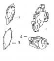
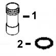
1 R67364 ELBOW FITTING 2 X
2 R51936 SEALING WASHER 6 X
3 RE66060 FUEL LINE 1 X (B) (SUB FOR RE63665)
4 R135106 CLAMP 1 X (SUB FOR R70407)
5 R67271 UNION FITTING 1 X
6 19H1731 CAP SCREW 1 X 3/8" X 1"
7 12H304 LOCK WASHER 1 X 3/8"
8 RE503559 FUEL LINE 1 X (SUB FOR RE63664)
9 28H1518 WASHER 1 X 0.493" X 0.675" X 5/16"
10 RE49589 FUEL LINE 1 -087549 X
RE501218 FUEL LINE 1 087550-090585 X (SUB RE504748)
RE504748 FUEL LINE 1 090586- X
11 R76358 O-RING 1 X
12 R121195 CAP SCREW 4 X
13 R121164 GEAR 1 X (SUB FOR R112975, THIS APPLICATION)
14 R67364 ELBOW FITTING 1 -087549 X
RE502650 FITTING 1 087550- X
15 R114130 STUD 4 X (SUB FOR R55396, THIS APPLICATION)
16 M72490 WASHER 4 X
17 14H1090 NUT 4 X 3/8", (SUB FOR E55662, THIS
APPLICATION)
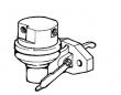
18 RE46252 FUEL PUMP 1 X (ROBERT BOSCH)
19 R67264 PACKING 2 X
20 AR87561 OIL LINE 1 X
21 AR88903 ELBOW FITTING 1 X
22 R79060 O-RING 1 X
23 RE63766 FUEL INJECTION PUMP 1 X (A) (ROBERT BOSCH) (ALSO ORDER R129240
AND (2) 19M8826)
24 R51936 SEALING WASHER 2 X
25 RE44030 OIL LINE 1 X
26 RE502650 FITTING 1 X (SUB FOR R63604)
27 AR87636 TEE FITTING 1 X
.. R83490 FITTING 1 X
(A) "SEE YOUR AUTHORIZED PUMP REPAIR STATION FOR PARTS NOT LISTED"
CONSULTEZ VOTRE REPARATEUR DE POMPE AGREE POUR LES PIECES NON CATALOGUES
NICHT GEZEIGTE TEILE VON PUMPENWERKSTAT BEZIEHEN.
PER LE PARTI NON ELENCATE, RIVOLGETEVI AL CENTRO AUTORIZZATO DI RIPARAZIONE POMPA
CONSULTE CON SU ESTACION AUTORIZADA RE PEPARACIONES DE BOMBA.
RAADGOER MED EN AUTORISERAD PUMPSERVICVERKSTAD BETRAEFFANDE EJ UPPTAGNA
(B) NOT AS ILLUSTRATED
DIFFERENT DE L’ILLUSTRATION
NICHT GEMAESS ABBILDUNG
NON COME ILLUSTRATO
DIFIERE DE LA ILUSTRACION
EJ SOM VISAD
POWERTECH 8.1 L OEM ENGINE (ESN -199999) PC2527 (21-JUN-01) 1600A-1651
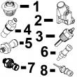
KEY PART NO. PART NAME QTY SERIAL NO. F F F REMARKS
1 R60914 SET SCREW 1 X
2 R53918 PACKING 1 X
3 T31556 NUT 1 X
4 R68715 PIN 1 X
5 AR89339 SEAL 1 X
6 AR89578 LEVER 1 X
7 24M7054 WASHER 1 X 6.400 X 12 X 1.600 MM
8 T24229 LOCK WASHER 2 X
9 R68716 NUT 1 X
10 R129240 LEVER 1 X (A)
R504886 LEVER 1 XXXXXX- X (A)
11 19M8826 SCREW 2 X M6 X 16
12 R53976 SCREW 1 X (B)
13 24H1287 WASHER 1 X (B) 9/32" X 5/8" X 0.065"
14 AR89552 LEVER 1 X (C)
15 R68438 RETAINER 1 X
16 R53955 O-RING 1 X
(A) THROTTLE (TWO HOLES AT TOP) (B) NOT INCLUDED (C) SHUT-OFF
MANETTE DES GAZ NON INCLUS ROBINET D’ARRET
DROSSELKLAPPE NICHT MIT ABSCHALTUNG
ACCELERATORE NON COMPRESO RUBINETTO D’ARRESTO
ACELERADOR NO FORMA PARTE GRIFO DECIERRE
GASREGLAGE INGAAR INTE AVSTAENGING