English
 Espaol
 Franais
 阿拉伯
阿拉伯 中文
中文 Deutsch
 Italiano
 Português
 日本
日本 韩国
韩国 български
 hrvatski
 esky
esky Dansk
Dansk Nederlands
 suomi
suomi Ελληνικ
 印度
印度 norsk
norsk Polski
 Roman
Roman русский
 Svenska
农业
5400
261581 >
5400N
8875
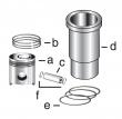
Skid Steer

| 设备型号 | 备注 |
|---|---|
| 3510 | Low Compression Piston. To ESN 199,999. Tier 1 |
| CH3510 | Low Compression Piston. To ESN 199,999. Tier 1 |
|
| ||||||||||||||||||||||||||||||
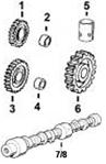
(1)螺旋齿轮。
(2)将所有R78558带帽螺丝替换为带法兰头帽螺丝TR85363。
(3)套管安装后,在装配活塞销之前,应使机器套管符合连杆的形状。
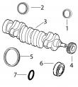
(4)套件包含TT20094斜齿轮转换为TRE50979曲轴。
(5)使用机器拆分连杆使用TR80033并使用断裂连杆TR501124。
(6)(m)R73604。
(7)(m)R100812,(m)R127337,(m)R127918,(m)R55164。
(8)与断裂分体连杆一起使用。
(9)检查您的应用程序是否正确使用。
(10)凸轮轴有一个40毫米宽的前轴承轴颈,用于转速计驱动的后部压力机,它将取代前轴承轴颈较窄的早期凸轮轴而没有任何问题。取代凸轮轴标志T20015,T20016,R79643,R106957和RE522311。
美国强鹿JOHN DEERE柴油发电机常见型号配件:
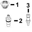
3029DF128、4039DF008、4045TF258、6068TF158、6068TF258、6068HF158、6068HF258、6081HF001A、6081HF001B、6125HF070A、6125HF070B,6125HF070C。5030HF270A 、6059TF005、6135H458。4045DFM70, 4045TFM75, 6068TFM75, 6068TFM76pn=254 camshaft&timing gear train repair&adjustment 02 050 9 rg,rg34710,1202 –19–23oct97–2/3 rg7215 –un–26nov97 camshaft gears a—camshaft gear b—injection pump drive gear 5. examine both camshaft gears (a)&injection pump drive gear (b) for worn/damaged gear teeth. gears should have a minimum backlash as follows: specification camshaft gear-to-injection pump drive gear backlash—backlash . 0.051 mm (0.0020 in.) minimum note: timing marks on crankshaft&camshaft gear should be aligned&no. 1 cylinder locked at “tdc compression” stroke when removing camshaft. rg,rg34710,1202 –19–23oct97–3/3 rg7057 –un–05dec97 removing camshaft a—thrust washer b—camshaft 6. carefully remove camshaft (b) from cylinder block so that camshaft lobes do not drag in bores. note: rotate camshaft carefully to aid in removing. 7. remove thrust washer (a) from behind cam gears. 8. remove cam followers from cylinder block. ctm86 (20mar01) 02-050-9 powertech? 8.1 l diesel engines — base engine 032001 pn=255 camshaft&timing gear train repair&adjustment 02 050 10 rg,rg34710,1203 –19–23oct97–1/1 remove camshaft gears rg5773 –un–26nov97 removing outer camshaft gear rg5774 –un–26nov97 removing inner camshaft gear a—outer camshaft gear b—inner camshaft gear important: prevent camshaft from striking floor when pushing camshaft nose out of gear. camshaft may be damaged if it is allowed to fall to the floor. note: camshaft gears are pressed onto the camshaft. removal of gears from camshaft will require approximately a 10-ton press. 1. support outer camshaft gear (a) in a press. 2. remove outer gear from camshaft. 3. support inner camshaft gear (b) in a press. 4. remove inner gear from camshaft. 5. clean camshaft&gears in solvent. dry with compressed air. ctm86 (20mar01) 02-050-10 powertech? 8.1 l diesel engines — base engine 032001 pn=256 camshaft&timing gear train repair&adjustment 02 050 11 rg,rg34710,1204 –19–23oct97–1/1 measure thrust washer thickness rg5775 –un–05dec97 measuring camshaft thrust washers 1. after removal of camshaft, check the two thrust washers individually for proper thickness. specification thrust washer—thickness . 2.24—2.34 mm (0.088—0.092 in.) 2. replace washers if worn/damaged. rg,rg34710,1205 –19–23oct97–1/1 inspect&measure camshaft followers rg2745 –un–04dec97 inspecting camshaft followers 1. inspect camshaft followers for uneven wear or damage. also inspect corresponding camshaft lobe for wear/damage. replace as necessary. 2. measure follower o.d.&follower bore i.d. in cylinder block. specification camshaft follower—od 17.33—17.35 mm (0.682—0.683 in.) camshaft follower bore in block—id 17.384—17.440 mm (0.6845—0.6865 in.) . replace cam followers that are not within specification. replace cylinder block if any one follower bore is not within specification. ctm86 (20mar01) 02-050-11 powertech? 8.1 l diesel engines — base engine 032001 pn=257 camshaft&timing gear train repair&adjustment 02 050 12 rg,rg34710,1206 –19–23oct97–1/1 visually inspect camshaft rg3500 –un–03nov97 inspecting camshaft a—camshaft lobes b—journals 1. clean camshaft in solvent. dry with compressed air. 2. inspect all camshaft lobes (a)&journals (b) for wear or damage. replace camshaft as necessary. new camshaft followers can be used with old camshaft (if camshaft is serviceable). do not reuse old camshaft followers with a new camshaft. note: very light score marks may be found but are acceptable if valve lift is within specification. pitting/galling dictates replacement. (see check valve lift serial number ( — 199,999) in group 020/see check valve lift serial number (200,000— ) in group 021.) rg,rg34710,1207 –19–23oct97–1/1 measure camshaft journal o.d.&bushing i.d. t81260 –un–07nov88 measuring camshaft journals 1. measure each camshaft journal o.d. if camshaft journal o.d. is not within specification, install a new camshaft. 2. measure each camshaft bushing i.d. when installed in cylinder block. compare measurements with specs given below. replace camshaft&bushings as needed. specification camshaft journal—od 66.987—67.013 mm (2.6373—2.6383 in.) new . camshaft bushing—i.d. 67.076—67.102 mm (2.6408—2.6418 in.) new ctm86 (20mar01) 02-050-12 powertech? 8.1 l diesel engines — base engine 032001 pn=258 camshaft&timing gear train repair&adjustment 02 050 13 rg,rg34710,1208 –19–23oct97–1/1 measure camshaft lobe lift t81262 –un–01nov88 measuring camshaft lobes measure each camshaft lobe at its highest point&at its narrowest point. subtract narrowest dimension from highest dimension to find camshaft lobe lift. if camshaft lobe lift is not within the wear specification on any one lobe, install a new camshaft. specification intake camshaft lobe—lift . 7.69—7.79 mm (0.303—0.307 in.) wear limit 7.19 mm (0.283 in.) exhaust camshaft lobe—lift 8.25—8.35 mm (0.325—0.329 in.) wear limit 7.75 mm (0.305 in.) ctm86 (20mar01) 02-050-13 powertech? 8.1 l diesel engines — base engine 032001 pn=259 camshaft&timing gear train repair&adjustment 02 050 14 rg,rg34710,1209 –19–23oct97–1/1 install camshaft gears rg5776 –un–26nov97 installing camshaft inner gear rg5777 –un–26nov97 installing camshaft outer gear a—woodruff key b—inner gear c—keyway d—outer gear 1. support camshaft under first bearing journal in a hydraulic press. 2. install woodruff key (a). lubricate camshaft nose with loctite? 51048 moly paste. 3. set inner gear (b) on camshaft with thrust washer surface to the inside (toward the camshaft). align woodruff key&keyway. 4. install gear onto nose of camshaft. push inner gear on until tight against the camshaft bearing journal. 5. set outer gear on camshaft with timing mark upward (away from the camshaft). align woodruff key and keyway (c) of outer gear (d). 6. push outer gear onto camshaft nose until tight against inner gear. 7. support each end of the camshaft on centers. use a dial indicator with plunger resting on the thrust surface of the camshaft gears. 8. check the runout of the inner&outer gear thrust surfaces. specification camshaft gear thrust surfaces— runout 0.10 mm (0.004 in.) maximum loctite is a trademark of loctite corp. ctm86 (20mar01) 02-050-14 powertech? 8.1 l diesel engines — base engine 032001 pn=260 camshaft&timing gear train repair&adjustment 02 050 15 dpsg,ouoe003,29 –19–18dec98–1/2 service camshaft bushings using jdg602 adapter set rg5272 –un–07nov97 removing camshaft bushings rg5949 –un–30aug91 camshaft rear bore plug a—bushing screw (jde6-1) b—cylinder block web c—lock bushing (no. 25916) d—receiver cup (jdg604) e—bushing driver (jdg603) f—camshaft bushing g—camshaft bore plug 1. inspect camshaft journals&bushings for wear or damage. measure cam journals&bushings to determine if proper oil clearance exists. replace camshaft and/or bushings as necessary. specification camshaft bushing—id 67.076—67.102 mm (2.6408—2.6418 in.) bore in block 69.987—70.013 mm (2.7554—2.7564 in.) . camshaft bore—runout 0.038 mm (0.0015 in.) maximum camshaft journal—od 66.987—67.013 mm (2.6373—2.6383 in.) . camshaft bushing-to-journal—oil clearance 0.063—0.115 mm (0.0025—0.0045 in.) note: the front two bushings can be reached from the front of the engine. the flywheel&rear camshaft bore plug (g) must be removed to reach the other two bushings. 2. remove camshaft bushings (f) using jdg603 bushing driver (e)&jdg604 receiver cup (d) along with the components shown from jde6 camshaft bushing replacement set (a&c). 3. tighten nut on end of bushing screw until bushing is pulled out of camshaft bushing bore. inspect and measure camshaft bushing bore in block (b). follow same procedure for remaining bushings to be replaced. continued on next page ctm86 (20mar01) 02-050-15 powertech? 8.1 l diesel engines — base engine 032001 pn=261 camshaft&timing gear train repair&adjustment 02 050 16 dpsg,ouoe003,29 –19–18dec98–2/2 rg5272 –un–07nov97 installing camshaft bushings a—bushing screw (jde6-1) b—cylinder block web c—lock bushing (no. 25916) d—receiver cup (jdg604) e—bushing driver (jdg603) f—camshaft bushing important: oil holes in bushings&cylinder block must be aligned after installation or oil starvation will occur. the elongated hole in bushing must be toward the top. after installation, use a small mirror with extension to be sure oil holes are properly aligned. 4. slide a new camshaft bushing (f) onto jdg603 bushing driver (e). assemble driver&jdgf604 receiver cup (d) along with components shown from jde6 camshaft bushing replacement set (a&c). 5. be sure bushing is started square in bore&oil holes are aligned with holes in block. tighten nut to pull bushing in until it is properly positioned in bore. 6. check bushing-to-cylinder block oil hole alignment using a small mirror with extension. ctm86 (20mar01) 02-050-16 powertech? 8.1 l diesel engines — base engine 032001 pn=262 camshaft&timing gear train repair&adjustment 02 050 17 dpsg,ouoe003,30 –19–18dec98–1/2 service camshaft bushings using jdg606 adapter set rg5332 –un–07nov97 removing camshaft bushings rg5949 –un–30aug91 camshaft rear bore plug a—bushing driver (jdg607) b—camshaft bushing c—cylinder block web d—slide hammer adapter (jdg408) e—bushing pilot (jdg608) f—slide hammer (d01299aa) g—camshaft bore plug 1. inspect camshaft journals&bushings for wear or damage. measure cam journals&bushings to determine if proper oil clearance exists. replace camshaft and/or bushings as necessary. specification camshaft bushing—id 67.076—67.102 mm (2.6408—2.6418 in.) bore in block 69.987—70.013 mm (2.7554—2.7564 in.) . camshaft bore—runout 0.038 mm (0.0015 in.) maximum camshaft journal—od 66.987—67.013 mm (2.6373—2.6383 in.) . camshaft bushing-to-journal—oil clearance 0.063—0.115 mm (0.0025—0.0045 in.) note: the front two bushings can be reached from the front to the engine. the flywheel&rear camshaft bore plug (g) must be removed to reach the other two bushings. lubricate o-ring on jdg608 bushing pilot with clean engine oil before installing in cylinder block web (c). 2. remove camshaft bushings (b) using jdg607 bushing driver (a)&jdg408 slide hammer adapter (d) (from jdg405 camshaft bushing service set). also use jdg608 bushing pilot (e),&d01299aa slide hammer (f). note: end bushing at front&rear of cylinder block may be removed with just jdg607 bushing driver and d01299aa slide hammer. 3. inspect&measure each camshaft bushing bore in block as bushings are removed. continued on next page ctm86 (20mar01) 02-050-17 powertech? 8.1 l diesel engines — base engine 032001 pn=263 camshaft&timing gear train repair&adjustment 02 050 18 dpsg,ouoe003,30 –19–18dec98–2/2 rg5333 –un–07nov97 installing camshaft bushings a—bushing driver (jdg607) b—camshaft bushing c—cylinder block web d—slide hammer adapter (jdg408) e—slide hammer (d01299aa) important: oil holes in bushings&cylinder block must be aligned after installation. the elongated hole in bushing must be toward the top. after installation, use a small mirror with extension to be sure oil holes are properly aligned. 4. slide a new camshaft bushing (b) onto jdg603 bushing driver (a). with jdg608 bushing pilot installed in outside cylinder block web (c), assemble d01299aa slide hammer (e)&jdg408 slide hammer adapter (d) with bushing driver as shown. 5. be sure bushing is started square in bore&oil holes are aligned with holes in block. pull bushing into bore with slide hammer until properly positioned. 6. check bushing-to-cylinder block oil hole alignment using a small mirror with extension. 7. apply permatex? aviation (form-a-gasket no. 3) to new camshaft bore steel cap plug&install plug in bore. plug edge must be seated below edge of bore. permatex is a registered trademark of loctite corporation. ctm86 (20mar01) 02-050-18 powertech? 8.1 l diesel engines — base engine 032001 pn=264 camshaft&timing gear train repair&adjustment 02 050 19 rg,rg34710,1210 –19–23oct97–1/2 install camshaft rg5780 –un–26nov97 camshaft thrust washer a—thrust washer important: set engine at tdc of no. 1 piston’s compression stroke before installing camshaft so timing marks on camshaft and crankshaft gears will be aligned. 1. if camshaft followers were removed with engine on a rollover stand, reinstall followers but do not obstruct camshaft bore. roll engine to an angle where followers fall away from camshaft bores. note: if d15001nu magnetic holding tool set is used, hold camshaft followers away from camshaft bore until camshaft is installed. 2. lubricate thrust washer (a) with ty6333/ty6347 high temperature grease&install on camshaft behind inner gear. 3. lubricate camshaft lobes with ty6333/ty6347 high temperature grease&bearing journals with clean engine oil. 4. carefully install camshaft in cylinder block so that camshaft lobes do not drag in bores. rotate camshaft during installation to avoid obstruction in any bore. rg,rg34710,1210 –19–23oct97–2/2 rg6614 –un–05dec97 timing marks—camshaft&crankshaft gears a—timing marks 5. with no. 1 piston on “tdc” compression, align timing marks (a) on camshaft&crankshaft gears. check injection pump timing. ctm86 (20mar01) 02-050-19 powertech? 8.1 l diesel engines — base engine 032001 pn=265 camshaft&timing gear train repair&adjustment 02 050 20 rg,rg34710,1211 –19–10jun99–1/2 install thrust washer&timing gear cover rg7060 –un–26nov97 thrust washer in timing gear cover rg7050 –un–26nov97 1-6 - sequence for tightening cover cap screws a—timing gear cover b—injection pump drive gear cover c—coolant pump&cover assembly 1. lubricate thrust washer (bold arrow) with ty6333 or ty6347 high temperature grease&install in timing gear cover (a) tabs. 2. install a new gasket on engine block. apply a light film of grease to the gasket to hold it in place. 3. using a new gasket, install the auxiliary drive housing with gear onto the timing gear cover. see remove, inspect&install crankshaft gear-driven auxiliary drive, earlier in this group.) important: tightening the timing gear cover cap screws in proper sequence controls the total runout of the crankshaft flange-to-oil seal bore. tighten auxiliary drive housing to timing gear cover&to cylinder block prior to tightening the timing gear cover to cylinder block. see remove, inspect&install crankshaft gear-driven auxiliary drive earlier in this group. 4. install timing gear cover. tighten cap screws one through six to specifications. specification timing gear cover-to-cylinder block cap screws—torque 27 n?m (20 lb-ft) 5. install coolant pump&cover assembly (c) using a new gasket. tighten cap screws to specifications. coolant pump cover-to-timing gear cover—specification 5/16-in. cap screws—torque . 27 n?m (20 lb-ft) 3/8-in. cap screws—torque . 47 n?m (35 lb-ft) 6. check camshaft endplay. see check camshaft end play&measure gear backlash earlier in this group.) 7. install injection pump drive gear cover (b) using a new gasket&tighten cap screws to specifications. ctm86 (20mar01) 02-050-20 powertec, h? 8.1 l diesel engines — base engine 032001 pn=266 continued on next page camshaft&timing gear train repair&adjustment 02 050 21 rg,rg34710,1211 –19–10jun99–2/2 specification injection pump drive gear cover—torque 27 n?m (20 lb-ft) 8. trim timing gear cover gasket flush with oil pan gasket rail. rg,rg34710,1212 –19–23oct97–1/1 complete final assembly 1. install a new crankshaft front wear sleeve&oil seal. see install crankshaft front oil seal in group 040. 2. connect the magnetic speed sen*** wiring lead. 3. install crankshaft vibration damper. see install vibration damper in group 040. 4. install valve train&rocker arm assembly. see install cylinder head&cap screws serial number ( —199,999) in group 020/see install cylinder head&cap screws serial number (200,000— ) in group 021. 5. install oil pan using a new gasket/install engine into vehicle if equipped with a structural oil pan. see install engine oil pan in group 060. fill engine with clean engine oil. 6. perform engine break-in as required. see perform engine break-in serial number ( —199,999) in group 020,/see perform engine break-in serial number (200,000— ) in group 021. ctm86 (20mar01) 02-050-21 powertech? 8.1 l diesel engines — base engine 032001 pn=267 camshaft&timing gear train repair&adjustment 02 050 22 ctm86 (20mar01) 02-050-22 powertech? 8.1 l diesel engines — base engine 032001 pn=268 group 060 lubrication system repair&adjustment 02 060 1 rg,rg34710,1215 –19–27apr99–1/1 diagnosing lubrication system malfunctions engine oil pressure (with engine warm) should be as follows: specification engine—oil pressure (engine warm) 280—400 kpa (2.8—4.0 bar) (40—58 psi) @ 1800-2000 rpm low oil pressure: ? low oil level. ? clogged cooler/filter. ? excessive oil temperature. ? incorrect oil. ? oil pressure regulating valve failure. ? excessive main/rod bearing clearance. ? clogged oil pump screen. ? excessive clearance between oil pump gears and cover. ? piston cooling orifice not installed. high oil pressure: ? improper oil classification. ? clogged oil lines. ? crimped/clogged ventilator outlet hose and adapter on rocker arm cover. ? oil pressure regulating valve failure. oil sludge&dilution: ? improper operation&servicing. ? coolant leakage into lubrication system. ? incomplete combustion. ? excessive oil consumption. ? defective injection pump (failed internal o-ring seals). low oil pressure at slow idle: ? bypass oil check valve failure. ctm86 (20mar01) 02-060-1 powertech? 8.1 l diesel engines — base engine 032001 pn=269 lubrication system repair&adjustment 02 060 2 rg,rg34710,1216 –19–23oct97–1/1 oil filter base&oil pressure regulating valve housing assembly rg7008 –un–05dec97 oil filter base&oil pressure regulating valve housing assembly a—oil filter base e—oil pressure regulating h—spring m—spring b—oil filter adapter valve housing j—o-ring n—o-ring c—oil filter with packing f—gasket k—plug o—plug d—oil tubes g—oil pressure regulating l—oil filter bypass valve valve ctm86 (20mar01) 02-060-2 powertech? 8.1 l diesel engines — base engine 032001 pn=270 lubrication system repair&adjustment 02 060 3 rg41165,0000033 –19–20dec00–1/1 top-load oil filter assembly rg11581 –un–19jan01 top-load oil filter assembly a—screw cap b—o-ring c—filter element d—oil filter housing e—pressure regulating valve f—spring g—plug h—flex fitting i—adapter plate assembly j—seal ctm86 (20mar01) 02-060-3 powertech? 8.1 l diesel engines — base engine 032001 pn=271 lubrication system repair&adjustment 02 060 4 rg41165,0000034 –19–20dec00–1/1 changing top-load oil filter rg11629a –un–20dec00 top-load oil filter cap rg11628 –un–01feb01 strike on surface to remove filter a—cap 1. use a wrench to unscrew cap (a). wait 30 seconds to allow oil filter housing to drain. remove cap&filter assembly. 2. while holding on to screw cap, strike filter element against a solid surface as shown to disconnect filter from cap. discard used filter. 3. remove o-ring seal&replace with new o-ring provided with new filter element. 4. press new filter into cap until it snaps into place. 5. insert cap&filter assembly into oil filter housing. screw cap in place. 6. use wrench to tighten cap to specification. specification top-load oil filter cap—torque . 40—50 n?m (30—37 lb-ft) ctm86 (20mar01) 02-060-4 powertech? 8.1 l diesel engines — base engine 032001 pn=272 lubrication system repair&adjustment 02 060 5 dpsg,ouo1004,842 –19–27apr99–1/2 remove&install oil filter base&oil pressure regulating valve housing rg7216 –un–26nov97 oil filter base?ulating valve housing a—oil filter base b—oil tubes c—oil pressure regulating valve housing remove oil filter base&pressure regulating valve housing: 1. disconnect turbocharger oil inlet line connector from top of oil filter base (a) (shown disconnected). 2. remove oil filter using a suitable filter wrench (shown removed). 3. remove two cap screws securing oil filter base to cylinder block. remove oil filter base&oil tubes (b). remove&discard four o-rings. 4. remove three cap screws securing oil pressure regulating valve housing (c) to cylinder block and remove housing. clean all gasket material from both mating surfaces. install oil filter base&pressure regulating valve housing: note: refer to oil filter base&oil pressure regulating valve housing assembly, earlier in this group. 1. install oil pressure regulating valve housing (e) using a new gasket. install new, stronger-grade cap screws. tighten new screws to specifications. specification oil pressure regulating valve housing-to-cylinder block (external)—torque 61 n?m (45 lb-ft) 2. install new o-ring in housing o-ring bores, lubricate o-rings with clean engine oil,&install oil tubes. 3. lubricate new o-rings with clean engine oil&install in oil filter base o-ring bores. install base onto oil tubes. 4. position filter base (a) on cylinder block, install cap screws,&tighten cap screws to specifications. ctm86 (20mar01) 02-060-5 powertech? 8.1 l diesel engines — base engine 032001 pn=273 continued on next page lubrication system repair&adjustment 02 060 6 dpsg,ouo1004,842 –19–27apr99–2/2 specification oil filter housing-to-cylinder block—torque . 80 n?m (60 lb-ft) 5. connect turbocharger oil line connector at top of filter base&tighten securely. 6. if removed, install new o-rings&tighten valve plugs (k&o) to specifications. specification oil filter bypass valve plug— torque . 100 n?m (74 lb-ft) oil pressure regulating valve plug—torque . 100 n?m (74 lb-ft) 7. if oil filter adapter (b) was removed, coat threads of adapter with loctite? 242 thread lock&sealer and reinstall adapter. 8. spread a layer of clean engine oil on new filter packing. install filter&tighten until packing contacts filter base. tighten an additional 1/2—3/4 turn after packing contacts base. do not overtighten oil filter. loctite is a registered trademark of loctite corp. ctm86 (20mar01) 02-060-6 powertech? 8.1 l diesel engines — base engine 032001 pn=274 lubrication system repair&adjustment 02 060 7 rg,rg34710,1218 –19–23oct97–1/1 engine oil cooler assembly rg7009 –un–05dec97 engine oil cooler assembly a—oil cooler cover/bypass c—oil cooler f—tube adapter j—spring valve housing d—cooler-to-block gasket g—adapter-to-block gasket k—o-ring b—cover-to-cooler gasket e—oil cooler tubes (2 used) h—oil cooler bypass valve l—plug ctm86 (20mar01) 02-060-7 powertech? 8.1 l diesel engines — base engine 032001 pn=275 lubrication system repair&adjustment 02 060 8 dpsg,ouo1004,821 –19–27apr99–1/2 remove, inspect,&install engine oil cooler rg7217 –un–12jan98 removing oil cooler rg7218 –un–26nov97 removing oil cooler rg7219 –un–28nov97 oil cooler removed a—oil cooler cover/bypass valve housing b—oil cooler tube adapter c—oil cooler tubes d—oil cooler see engine oil cooler assembly, earlier in this group for exploded view of engine oil cooler assembly. remove oil cooler assembly: 1. remove eight cap screws securing oil cooler cover (a). 2. remove two cap screws securing oil cooler tube adapter (b). remove cover, tubes (c),&adapter as an assembly. 3. remove oil cooler (d) from block bore. clean all gasket material from mating surfaces. inspect oil cooler assembly: 1. inspect oil cooler for physical damage, plugging, or leakage which may allow mixing of oil&coolant. 2. back flush oil cooler to clean all debris from core. 3. pressure test oil cooler in liquid&compressed air if mixing of oil&coolant is suspected. oil cooler should show no leakage when 140-170 kpa (1.4—1.7 bar) (20—25 psi) air pressure is applied for a minimum of 30 seconds. 4. inspect all remaining parts of oil cooler assembly. replace parts as needed. do not attempt to repair oil cooler. continued on next page ctm86 (20mar01) 02-060-8 powertech? 8.1 l diesel engines — base engine 032001 pn=276 lubrication system repair&adjustment 02 060 9 dpsg,ouo1004,821 –19–27apr99–2/2 rg7261 –un–05dec97 sequence for tightening cover screws a—oil cooler cover install oil cooler assembly: 1. install oil cooler using a new gasket on each side of cooler. be sure gaskets are properly aligned with cap screw holes. note: if cover, tubes,&adapter were disassembled, lubricate new o-rings with clean engine oil. 2. install a new gasket on cylinder block&install oil cooler cover, tubes,&adapter as an assembly. tighten adapter cap screws to specifications. specification oil cooler adapter cap screws— torque . 47 n?m (35 lb-ft) 3. tighten oil cooler cover (a) cap screws in sequence shown (1-8). apply initial torque as follows: specification oil cooler cover-to-cylinder block cap screws—initial torque . 20 n?m (15 lb-ft) then retighten in same sequence to final torque specification. specification oil cooler cover-to-cylinder block—final torque 37 n?m (27 lb-ft) ctm86 (20mar01) 02-060-9 powertech? 8.1 l diesel engines — base engine 032001 pn=277 lubrication system repair&adjustment 02 060 10 rg,rg34710,1220 –19–23oct97–1/2 remove, inspect,&install oil pressure regulating valve, oil filter bypass valve, and oil cooler bypass valve see oil filter base&oil pressure regulating valve housing assembly&see engine oil cooler assembly, earlier in this group, for illustration of valves. oil pressure regulating valve: 1. remove plug (k), o-ring (j), spring (h), oil pressure regulating valve (g) from housing (e). discard o-ring. 2. inspect valve&valve bore for damage. replace if necessary. 3. check spring for proper compression. replace spring if not within specification. specification pressure regulating valve spring—compressed length 43.0 mm (1.69 in.) @ 66—74 n (15—17 lb-force) . free length . 85.0 mm (3.35 in.) 4. dip all parts in clean engine oil; insert valve and spring in housing. 5. install plug (k) using a new o-ring&tighten to specifications. specification oil pressure regulating valve plug—torque 100 n?m (74 lb-ft) note: pressure regulating valve starts to operate at 340 kpa (3.4 bar) (49 psi). specification oil pressure regulating valve—operating pressure (starts to operate) . 340 kpa (3.4 bar) (49 psi) oil filter bypass valve: 1. remove plug (o) with o-ring (n), spring (m), and oil filter bypass valve (l) from oil filter base (a). discard o-ring. 2. inspect valve&housing bore for scoring or damage. replace if necessary. 3. check spring for proper compression. replace spring if not within specification. specification oil filter bypass valve spring—compressed length 30.0 mm (1.18 in.) @ 64—78 n (14—18 lb-force) . free length . 44.0 mm (1.73 in.) 4. dip all parts in clean engine oil; insert valve and spring in filter base. 5. install new o-ring on plug (o). install plug and tighten to specifications. specification oil filter bypass valve plug— torque . 100 n?m (74 lb-ft) note: filter bypass valve operating pressure is 220 kpa (2.20 bar) (32 psi). specification oil filter bypass valve— operating pressure 220 kpa (2.20 bar) (32 psi) oil cooler bypass valve: 1. remove plug (l), o-ring (k), spring (j),&oil cooler bypass valve (i) from oil cooler cover/bypass valve housing (a). discard o-ring. 2. check housing for clogged passages&all other parts for scale build-up. 3. clean all parts with a stiff bristle brush&solvent, if necessary. dry with compressed air. 4. inspect bypass valve for damage. replace if necessary. ctm86 (20mar01) 02-060-10 powertech? 8.1 l diesel engines — base engine 032001 pn=278 continued on next page lubrication system repair&adjustment 02 060 11 rg,rg34710,1220 –19–23oct97–2/2 5. check bypass valve spring for proper specifications. replace spring if not within specification. specification oil cooler bypass valve spring—compressed length 30.0 mm (1.18 in.) @ 64—78 n (14—18 lb-force) . free length . 44.0 mm (1.73 in.) 6. dip all parts in clean engine oil; insert valve (i) and spring (j) in housing bore. 7. install new o-ring on plug (l)&tighten to specifications. specification oil cooler bypass valve plug— torque . 100 n?m (74 lb-ft) note: cooler bypass valve operating pressure is 220 kpa (2.20 bar) (32 psi). specification oil cooler bypass valve— operating pressure 220 kpa (2.20 bar) (32 psi) rg,rg34710,1221 –19–23oct97–1/1 remove engine from 8000 tractors for access to engine oil pump 6081hrw engines used in 8000 series tractors are equipped with a front frame/oil sump which is also a structural member of the vehicle. for access to the engine oil pump, the engine must be removed from the vehicle. refer to tm1575 (8100, 8200, 8300,&8400 tractors— repair) for engine removal instructions. (for tracks models, refer to tm1621.) dpsg,ouo1004,822 –19–21apr99–1/1 remove oil pan removing oil pan will allow access to engine oil pump. 1. drain engine oil. 2. remove oil pan&discard gasket. 3. remove all gasket material from oil pan rail and cylinder block mounting surfaces. important: oil pan cap screws should have only one flat washer&no lockwasher. if cap screws have flat washers with lock washers, discard them&replace with new hardened flat washers. ctm86 (20mar01) 02-060-11 powertech? 8.1 l diesel engines — base engine 032001 pn=279 lubrication system repair&adjustment 02 060 12 dpsg,ouo1004,843 –19–27apr99–1/1 check crankshaft gear-to-oil pump drive gear backlash rg5914 –un–05dec97 measuring oil pump drive gear backlash a—dial indicator b—pump drive gear c—crankshaft gear important: backlash must be at least 0.08 mm (0.003 in.) for helical gear&at least 0.10 mm (0.004 in.) for spur gear. if backlash is less than specification, replace the oil pump drive gear. before removing oil pump, determine if there is adequate backlash between oil pump&crankshaft drive gears. specification crankshaft helical gear-to-oil pump drive gear—backlash 0.08 mm (0.003 in.) minimum crankshaft spur gear-to-oil pump drive gear—backlash 0.10 mm (0.004 in.) minimum mount dial indicator (a)&measure backlash between pump drive gear (b)&crankshaft gear (c). check oil pump gear-to-crankshaft throw clearance. specification oil pump helical gear-to-crankshaft throw— clearance 0.38 mm (0.0015 in.) minimum dpsg,ouo1004,844 –19–27apr99–1/2 remove engine oil pump rg9043 –un–28apr99 remove oil pump a—drive gear retaining nut b—oil pump housing cap screws 1. loosen drive gear retaining nut (a) one full turn. 2. re, move four oil pump housing cap screws with washers (b). important: some early engines used grade 5 oil pump mounting cap screws. replace these cap screws with new grade 8 cap screws when reinstalling pump. 3. lift up on oil pump assembly&wiggle assembly left-to-right to disengage housing from mounting dowels. ctm86 (20mar01) 02-060-12 powertech? 8.1 l diesel engines — base engine 032001 pn=280 continued on next page lubrication system repair&adjustment 02 060 13 dpsg,ouo1004,844 –19–27apr99–2/2 rg9046 –un–28apr99 remove oil pump a—outlet tube b—pickup tube c—oil pump drive gear 4. once pump assembly is free from dowels, swing assembly to the right (as viewed from flywheel end) and disengage outlet tube (a) from pump housing. 5. remove oil pump drive gear (c)&oil pickup tube (b) from pump. rg,rg34710,1225 –19–23oct97–1/1 inspect&clean oil pump 1. visually inspect oil pump for wear/damage. important: do not disassemble engine oil pump for flushing, inspection, or performing wear checks. individual components of oil pump are not available through service parts. replace pump as a complete assembly. never hammer directly on oil pump housing as it could cause binding of gears. 2. flush pump assembly internally with clean solvent to remove oil. spin pump gears to help remove solvent. pump gears should move 盐城美国JohnDeere柴滤RE533910哪家买,阜新约翰迪尔4045柴油机连杆哪里买,成都强鹿6090柴油发动机挺铜柱的价格,渭南强鹿6090柴油发动机气缸室盖垫代理,内江JohnDeereR98062进气门公司,马鞍山约翰迪尔RE19278公司,临夏约翰迪尔发动机副线束哪里买,襄阳强鹿6090柴油机活塞哪家好,阜阳约翰迪尔发动机节温器座一级代理,丹东约翰迪尔强鹿4045柴油机密封圈修理包代理商,威海强鹿滤芯滤清器RE64449厂家批发,常州强鹿缸套组件RE506961批发商,三明强鹿3029柴油机连杆瓦的价格,包头强鹿柴油发动机喷油嘴批发价,freely. 3. place oil pump on a work bench with pump-to-cylinder block mounting surface facing upward (same as when mounted on engine). important: to help insure accurate wear measurements, be sure the oil pump is clean&faces the same way as when mounted on the cylinder block. note: leave pump drive gear installed when making checks. ctm86 (20mar01) 02-060-13 powertech? 8.1 l diesel engines — base engine 032001 pn=281 lubrication system repair&adjustment 02 060 14 rg,rg34710,1226 –19–23oct97–1/1 check drive shaft end play rg5916 –un–05dec97 checking pump shaft end play 1. mount dial indicator with indicator plunger resting against end of pump drive shaft. 2. move shaft toward&away from indicator. if end play exceeds specification, there is excessive wear on pump cover and/or wear on end of pump drive gear. KEY PART NO. PART NAME QTY OR PUMP DATE F F F REMARKS
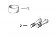
1 R63059 SPRING 1 X X
2 R63060 PISTON 1 X X
3 R67886 O-RING 1 X X
4 R67885 HOUSING 1 X X
5 R63063 SCREW 2 X X
6 R54880 LOCK WASHER 2 X X
7 R62104 VALVE 1 X X
8 R62105 PIN FASTENER 1 X X
9 R26373 SPRING 1 X X
10 R62107 WASHER 2 X X
11 R62106 SCREW 1 X X
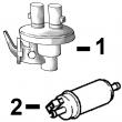
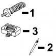
KEY PART NO. PART NAME QTY SERIAL NO. F F F REMARKS
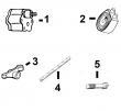
1 RE65265 HAND PRIMER 1 X (SUB FOR RE48048)
2 R54025 WASHER 1 X
3 R26448 O-RING 2 X
4 RE10258 ELBOW FITTING 2 X (M14 X 5/8 IN.)
5 R67879 GASKET 1 X
6 RE46375 FUEL PUMP 1 X (ROBERT BOSCH)
7 R93008 WASHER 1 X
8 R83490 FITTING 1 X
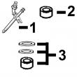
KEY PART NO. PART NAME QTY SERIAL NO. F F F REMARKS
1 R64927 O-RING 1 X
2 R64854 WASHER 2 X
3 AR81825 HAND PRIMER 1 X
4 RE48606 FUEL PUMP 1 X (DENSO)
5 RE10258 ELBOW FITTING 1 X (OUT)
RE34128 ELBOW FITTING 1 X (IN)
6 R26448 O-RING 2 X
.. 51M4236 SEALING RING 1 X
.. R83489 FITTING 1 X
.. R53901 WASHER 1 X