English
 Espaol
 Franais
 阿拉伯
阿拉伯 中文
中文 Deutsch
 Italiano
 Português
 日本
日本 韩国
韩国 български
 hrvatski
 esky
esky Dansk
Dansk Nederlands
 suomi
suomi Ελληνικ
 印度
印度 norsk
norsk Polski
 Roman
Roman русский
 Svenska
农业
6430
6534
7130


|
| ||||||||||||||||||||||||||||
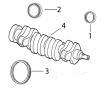
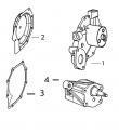
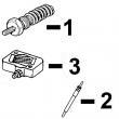
(1)1件组合式密封和穿套; 替换TRE59810,RE538097。
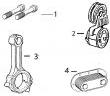
(2)在曲轴加工过程中必须保持正确的轴承轴颈半径,以确保正确操作。
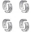
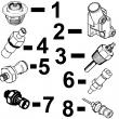
(3)锥形鼻子。
(4)直鼻。
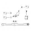
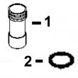
(5)检查应用程序是否正确使用。
(6)线路连接都是线程化的。
(7)线路连接是一个软管倒钩& 一个线程。
(8)线路连接是两个软管倒钩。
强鹿JOHN DEERE柴油机配件、发动机配件、发电机组:
T19044、RE62418、RE62419、RE521248、RE520842、C085004、RE509672、RE196945、RE191915、RE522688、RE522687、RE519774、RE532628、RE507980、RE531703、RE24619、RE187966、RE205726、RE507264、RE504836、RE509036、RE533910、RE532952、RE530107、RE508971/
强鹿JOHN DEERE柴油机配件、发动机配件、发电机组:
RE523502、RE518520、RE68345、RE53307、RE62240、RE533095、RE502513、RE38009、R30402、RE521538、RE521540、RE62240、P524837、RE60021、RE507236、RE59588、RE549153、RE530870、SE501610、SE501609、RE70960(cd3029df,cd4039df/tf,cd4045tf,cd6059tf,cd6068tf) pc2450 (30-nov-95) pn=316 2e9 air cleaner 3 4 0 0 2 3 engine 9 9 key part no- part name qty serial no- d d remarks 1 ah104837 clamp 2 x x 2 r122864 hose 1 -263023 x (1804) r131129 hose 1 263024- x (1804) r122843 hose 1 x (1802) 3 re58919 air cleaner 1 x x assy,incl-keys 6,7 4 re35507 prescreener 1 x x 5 re41931 clamp 1 x x 6 - valve 1 x r132750 valve 1 x x 7 pe71011292 filter element 1 x x 8 19h2127 cap screw 2 x x 5/16" x 7/8" 9 24h1136 washer 2 x x 11/32" x 11/16" x 0-065" 10 r128755 bracket 1 x x (sub for re58914) 11 19h2284 cap screw 1 x x 3/8" x 7/8" 12 12h304 lock washer 1 x x 3/8" 13 24h1305 washer 1 x x 13/32" x 13/16" x 0-065" 14 12m7056 lock washer 2 x x 8-100 mm 15 14h785 nut 2 x x 5/16" 16 19h1895 cap screw 1 x x 1/2" x 3/4" 17 re58918 clamp 1 x x id 182mm (7-16") genset power units (cd3029df,cd4039df/tf,cd4045tf,cd6059tf,cd6068tf) pc2450 (20-jan-98) 60-3 pn=317 2e10 air cleaner air cleaner, code 1805 filtre a air, code 1805 luftfliter-zusb- kode 1805 depuratore d’aria, codice 1805 filtro de aire, codigo 1805 luftrenare, koden 1805 cd40020 -un-22aug95 this parts listing is continued 60-4 genset power units (cd3029df,cd4039df/tf,cd4045tf,cd6059tf,cd6068tf) pc2450 (30-nov-95) pn=318 2e11 air cleaner 4 4 0 0 3 4 engine 9 5 key part no- part name qty serial no- t t remarks 1 ar21842 clamp 2 x x 2 r124883 hose 1 x x 3 re61094 air cleaner 1 x x assy,incl-keys 6,7 4 re33876 cap 1 x x 5 ah104837 clamp 1 x x 6 r132751 valve 1 x x 7 re62220 filter element 1 x x 8 19h2127 cap screw 2 x x 5/16" x 7/8" 9 24h1136 washer 2 x x 11/32" x 11/16" x 0-065" 10 r128755 bracket 1 x x (sub for re58914) 11 19h2284 cap screw 1 x x 3/8" x 7/8" 12 12h304 lock washer 1 x x 3/8" 13 24h1305 washer 1 x x 13/32" x 13/16" x 0-065" 14 12m7056 lock washer 2 x x 8-100 mm 15 14h785 nut 2 x x 5/16" 16 19h1895 cap screw 1 x x 1/2" x 3/4" 17 re61095 clamp 1 x x id 212mm (8-34") genset power units (cd3029df,cd4039df/tf,cd4045tf,cd6059tf,cd6068tf) pc2450 (20-jan-98) 60-5 pn=319 2e12 air cleaner air cleaner, code 1803 filtre a air, code 1803 luftfliter-zusb- kode 1803 depuratore d’aria, codice 1803 filtro de aire, codigo 1803 luftrenare, koden 1803 cd40020 -un-22aug95 this parts listing is continued 60-6 genset power units (cd3029df,cd4039df/tf,cd4045tf,cd6059tf,cd6068tf) pc2450 (30-nov-95) pn=320 2e13 air cleaner 6 6 0 0 5 6 engine 9 8 key part no- part name qty serial no- t t remarks 1 ar21842 clamp 2 x x 2 r124647 hose 1 x x 3 re61094 air cleaner 1 x x assy,incl-keys 6,7 4 re33876 cap 1 x x 5 ah104837 clamp 1 x x 6 r132751 valve 1 x x 7 re62220 filter element 1 x x 8 19h2127 cap screw 2 x x 5/16" x 7/8" 9 24h1136 washer 2 x x 11/32" x 11/16" x 0-065" 10 r128755 bracket 1 x x (sub for re58914) 11 19h2284 cap screw 1 x x 3/8" x 7/8" 12 12h304 lock washer 1 x x 3/8" 13 24h1305 washer 1 x x 13/32" x 13/16" x 0-065" 14 12m7056 lock washer 2 x x 8-100 mm 15 14h785 nut 2 x x 5/16" 16 19h1895 cap screw 1 x x 1/2" x 3/4" 17 re61095 clamp 1 x x id 212mm (8-34") 18 r124884 spacer 1 x x genset power units (cd3029df,cd4039df/tf,cd4045tf,cd6059tf,cd6068tf) pc2450 (20-jan-98) 60-7 pn=321 2e14 air cleaner air restriction indicator, code 7503 indicateur de colmatage, code 7503 verschmutzungsanzeiger, kode 7503 indicatore di ostruzione, codice 7503 indicador restriccionde aire, cidigo 7503 indikator, luftmotstaand, koden 7503 cd36589a -un-20jul95 a l key part no- part name qty serial no- l remarks 1 at25983 air restriction indicator 1 x 60-8 genset power units (cd3029df,cd4039df/tf,cd4045tf,cd6059tf,cd6068tf) pc2450 (30-nov-95) pn=322 2e16 belt/fan/radiator belt, 11/16" code 2402 courroie, 11/16" code 2402 riemen, 11/16" kode 2402 cinghia, 11/16" codice 2402 correa, 11/16" codigo 2402 rem, 11/16" koden 2402 cd35109 -un-01jan94 3 0 2 engine 9 key part no- part name qty serial no- d remarks 1 t24473 belt 1 x lgth 1295mm (51") genset power units (cd3029df,cd4039df/tf,cd4045tf,cd6059tf,cd6068tf) pc2450 (20-jan-98) 70-1 pn=323 2e17 belt/fan/radiator belt, 11/16" code 2402 courroie, 11/16" code 2402 riemen, 11/16" kode 2402 cinghia, 11/16" codice 2402 correa, 11/16" codigo 2402 rem, 11/16" koden 2402 cd35109 -un-01jan94 4 4 4 0 0 0 3 3 4 engine 9 9 5 key part no- part name qty serial no- d t t remarks 1 t24473 belt 1 x x x lgth 1295mm (51") 70-2 genset power units (cd3029df,cd4039df/tf,cd4045tf,cd6059tf,cd6068tf) pc2450 (20-jan-98) pn=324 2e18 belt/fan/radiator belt, 1/2" code 2410 courroie, 1/2" code 2410 riemen, 1/2" kode 2410 cinghia, 1/2" codice 2410 correa, 1/2" codogo 2410 rem, 1/2" koden 2410 cd37220 -un-01jan94 6 6 0 0 5 6 engine 9 8 key part no- part name qty serial no- t t remarks 1 re61115 belt set 1 x x lgth 1430mm (56-30") (kit (2) r79024) genset power units (cd3029df,cd4039df/tf,cd4045tf,cd6059tf,cd6068tf) pc2450 (20-jan-98) 70-3 pn=325 2e19 belt/fan/radiator blower fan, code 2503 ventilateur soufflant, code 2503 druckluefter, kode 2503 ventilatore, kode 2503 ventilador soplador, codigo 2503 tryckflaekt, koden 2503 cd40021 -un-22aug95 3 0 2 engine 9 key part no- part name qty serial no- d remarks 1 19h3131 cap screw 4 -263023 x 5/16" x 2" 2 12m7065 lock washer 4 -263023 x 8-100 mm 3 re58921 blower fan 1 -263023 x 70-4 genset power units (cd3029df,cd4039df/tf,cd4045tf,cd6059tf,cd6068tf) pc2450 (20-jan-98) pn=326 2e20 belt/fan/radiator blower fan, code 2512 ventilateur soufflant, code 2512 druckluefter, kode 2512 ventilatore, kode 2512 ventilador soplador, codigo 2512 tryckflaekt, koden 2512 cd39621 -un-17aug95 3 0 2 engine 9 key part no- part name qty serial no- d remarks 1 19h2127 cap screw 4 263024- x 5/16" x 7/8" 2 12m7056 lock washer 4 263024- x 8-100 mm 3 re47519 blower fan 1 263024- x od 457mm (18") 4 - hub na 263024- x genset power units (cd3029df,cd4039df/tf,cd4045tf,cd6059tf,cd6068tf) pc2450 (20-jan-98) 70-5 pn=327 2e21 belt/fan/radiator blower fan, code 2501 ventilateur soufflant, code 2501 druckluefter, kode 2501 ventilatore, kode 2501 ventilador soplador, codigo 2501 tryckflaekt, koden 2501 cd40022 -un-22aug95 4 4 4 0 0 0 3 3 4 engine 9 9 5 key part no- part name qty serial no- d t t remarks 1 19h2127 cap screw 4 x x x 5/16" x 7/8" 2 12m7065 lock washer 4 x x x 8-100 mm 3 24h1292 washer 4 x x x 11/32" x 3/4" x 0-120" 4 at31819 blower fan 1 x x x 0d 533mm (21") 70-6 genset power units (cd3029df,cd4039df/tf,cd4045tf,cd6059tf,cd6068tf) pc2450 (30-nov-95) pn=328 2e22 belt/fan/radiator blower fan, code 2501, 911y ventilateur soufflant, code 2501, 911y druckluefter, kode 2501, 911y ventilatore, kode 2501, 911y ventilador soplador, codigo 2501, 911y tryckflaekt, koden 2501, 911y cd36576a -un-22aug95 6 6 0 0 5 6 engine 9 8 key part no- part name qty serial no- t t remarks 1 19h2284 cap screw 4 x x 3/8" x 7/8" 2 12m7065 lock washer 4 x x 8-100 mm 3 at24834 blower fan 1 x x 0d 533mm (21") genset power units (cd3029df,cd4039df/tf,cd4045tf,cd6059tf,cd6068tf) pc2450 (20-jan-98) 70-7 pn=329 2e23 belt/fan/radiator radiator/shroud, code 2703 radiateur/buse, code 2703 kuehler/luefterhaubek, kode 2703 radiatore/protezione, codice 2703 radiator/coraza, codigo 2703 kylare/luftledare, koden 2703 cd40023a -un-29mar96 this parts listing is continued 70-8 genset power units (cd3029df,cd4039df/tf,cd4045tf,cd6059tf,cd6068tf) pc2450 (20-jan-98) pn=330 2e24 belt/fan/radiator 3 0 2 engine 9 key part no- part name qty serial no- d remarks 1 re62218 filler cap 1 -263023 x 60 kpa - 120 kpa (8-7 psi - 17-4 psi) 2 re58941 radiator 1 -263023 x assy 3 re62219 drain valve 1 -263023 x 4 ar65294 clamp 2 -263023 x 5 r122837 hose 1 -263023 x thermostat cover/radiator, couvercle de thermostat/radiateur, thermostatdeckel/ kuehler, coperchio termostato/radiatore, tapadera termostato/radiator, skyddskaapa termostat/kylare 6 ar21839 clamp 2 -263023 x 7 r122836 hose 1 -263023 x radiator/water pump, radiateur/pompe a eau, kuehler/wasserpumpe, radiatore/pompa dell’ acqua, radiator/bomba de agua, kylare/ vattenpump genset power units (cd3029df,cd4039df/tf,cd4045tf,cd6059tf,cd6068tf) pc2450 (20-jan-98) 70-9 pn=331 2f1 belt/fan/radiator radiator/rubber mounts/grate, code 2703 radiateur/supports elastiques/grille, code 2703 kuehler/gummilager/gitter, kode 2703 radiatore/supporto in gomma/griglia, codice 2703 radiador/soporte de goma/rejilla, codigo 2703 kylare/gummilager/galler, koden 2703 cd40024a -un-28mar96 this parts listing is continued 70-10 genset power units (cd3029df,cd4039df/tf,cd4045tf,cd6059tf,cd6068tf) pc2450 (20-jan-98) pn=332 2f2 belt/fan/radiator 3 0 2 engine 9 key part no- part name qty serial no- d remarks 1 re58911 grate 1 -263023 x 2 19m7662 cap screw 2 -263023 x m10 x 30 3 24m7178 washer 2 -263023 x 10-500 x 30 x 2-500 mm 4 r122831 strap 1 -263023 x 5 12m7135 lock washer 4 -263023 x 10-200 mm 6 14m7294 nut 2 -263023 x m10 7 19m7284 cap screw 1 -263023 x m8 x 18 8 24h1292 washer 1 -263023 x 11/32" x 3/4" x 0-120" 9 re64308 rubber mount 1 -263023 x 10 12m7056 lock washer 1 -263023 x 8-100 mm 11 14m7273 nut 5 -263023 x m8 12 19h2284 cap screw 1 -263023 x 3/8" x 7/8" 13 24h1305 washer 1 -263023 x 13/32" x 13/16" x 0-065" 14 r122835 reinforcement 1 -263023 x 15 19m7964 cap screw 4 -263023 x m8 x 12 16 re50898 rubber mount 2 -263023 x 17 19m8637 cap screw 2 -263023 x m10 x 40 genset power units (cd3029df,cd4039df/tf,cd4045tf,cd6059tf,cd6068tf) pc2450 (20-jan-98) 70-11 pn=333 2f3 belt/fan/radiator radiator/shroud, code 2705 radiateur/buse, code 2705 kuehler/luefterhaubek, kode 2705 radiatore/protezione, codice 2705 radiator/coraza, codigo 2705 kylare/luftledare, koden 2705 cd40025 -un-22aug95 this parts listing is continued 70-12 genset power units (cd3029df,cd4039df/tf,cd4045tf,cd6059tf,cd6068tf) pc2450 (20-jan-98) pn=334 2f4 belt/fan/radiator 3 0 2 engine 9 key part no- part name qty serial no- d remarks 1 re62221 filler cap 1 263024- x 80 kpa (11-6 psi) 2 re66397 radiator 1 263024- x assy 3 n10010 clip 2 263024- x 4 ar65294 clamp 3 263024- x 5 r131071 hose 1 263024- x thermostat cover/radiator, couvercle de thermostat/radiateur, thermostatdeckel/ kuehler, coperchio termostato/radiatore, tapadera termostato/radiator, skyddskaapa termostat/kylare 6 ar21839 clamp 1 263024- x 7 r124696 hose 1 263024- x radiator/water pump, radiateur/pompe a eau, kuehler/wasserpumpe, radiatore/pompa dell’ acqua, radiator/bomba de agua, kylare/ vattenpump 8 at18904 clamp 2 263024- x 9 r124792 hose 1 263024- x radiator/water pump, radiateur/pompe a eau, kuehler/wasserpumpe, radiatore/pompa dell’ acqua, radiator/bomba de agua, kylare/ vattenpump 10 re54885 hose fitting 1 263024- x (sub for r82859) 1/2"-14nptf 11 15h602 elbow fitting 1 263024- x 1/2"-14npt x 1/2"-14npt 12 re59019 shut-off valve 1 263024- x 13 15h584 pipe plug ar 263024- x 1/2"-14nptf 14 re63049 drain plug ar 263024- x m14 genset power units (cd3029df,cd4039df/tf,cd4045tf,cd6059tf,cd6068tf) pc2450 (20-jan-98) 70-13 pn=335 2f5 belt/fan/radiator radiator/rubber mounts/grate, code 2705 radiateur/supports elastiques/grille, code 2705 kuehler/gummilager/gitter, kode 2705 radiatore/supporto in gomma/griglia, codice 2705 radiador/soporte de goma/rejilla, codigo 2705 kylare/gummilager/galler, koden 2705 cd40037 -un-31oct97 this parts listing is continued 70-14 genset power units (cd3029df,cd4039df/tf,cd4045tf,cd6059tf,cd6068tf) pc2450 (20-jan-98) pn=336 2f6 belt/fan/radiator 3 0 2 9 key part no- part name qty year d remarks 1 19h1792 cap screw 1 263024- x 1/2" x 1" 2 24h1625 washer 1 263024- x 17/32" x 1" x 0-120" 3 r124762 reinforcement 1 263024- x lgth 259mm (10-15") 4 19m7964 cap screw 5 263024- x m8 x 12, for re64308 5 12m7056 lock washer ar 263024- x 8-100 mm 6 re64308 rubber mount 1 263024- x 7 19m7964 cap screw 5 263024- x m8 x 12 8 t30726 strap 1 263024- x 9 r127185 grate 1 263024- x l-h- 10 re63282 grate 1 263024- x r-h- 11 24m7055 washer 4 263024- x 8-400 x 16 x 1-600 mm 12 14m7273 nut ar 263024- x m8 13 19h2284 cap screw 4 263024- x 3/8" x 7/8" 14 24h1305 washer 4 263024- x 13/32" x 13/16" x 0-065" 15 12h304 lock washer 4 263024- x 3/8" 16 14h812 nut 4 263024- x 3/8" 17 r124761 strap 1 263024- x 18 re50898 rubber mount 2 263024- x 19 19m7284 cap screw 4 263024- x m8 x 18 20 19m7382 cap screw 2 263024- x m10 x 40 21 12m7135 lock washer 2 263024- x 10-200 mm 22 14m7274 nut 2 263024- x m10 genset power units (cd3029df,cd4039df/tf,cd4045tf,cd6059tf,cd6068tf) pc2450 (20-jan-98) 70-15 pn=337 2f7 belt/fan/radiator radiator/shroud, code 2703,2704 radiateur/buse, code 2703,2704 kuehler/luefterhaubek, kode 2703,2704 radiatore/protezione, codice 2703,2704 radiator/coraza, codigo 2703,2704 kylare/luftledare, koden 2703,2704 cd40025 -un-22aug95 this parts listing is continued 70-16 genset power units (cd3029df,cd4039df/tf,cd4045tf,cd6059tf,cd6068tf) pc2450 (20-jan-98) pn=338 2f8 belt/fan/radiator 4 4 4 0 0 0 3 3 4 engine 9 9 5 key part no- part name qty serial no- d t t remarks 1 re62221 filler cap 1 x x x 80 kpa (11-6 psi) 2 re61277 radiator 1 x x x assy 3 n10010 clip 2 x x x 4 ar65294 clamp 3 x x x 5 r124697 hose 1 x x thermostat cover/radiator, couvercle de thermostat/radiateur, thermostatdeckel/ kuehler, coperchio termostato/radiatore, tapadera termostato/radiator, skyddskaapa termostat/kylare (2703) r125043 hose 1 x thermostat cover/radiator, couvercle de thermostat/radiateur, thermostatdeckel/ kuehler, coperchio termostato/radiatore, tapadera termostato/radiator, skyddskaapa termostat/kylare (2704) 6 ar21839 clamp 1 x x x 7 r124696 hose 1 x x x radiator/water pump, radiateur/pompe a eau, kuehler/wasserpumpe, radiatore/pompa dell’ acqua, radiator/bomba de agua, kylare/ vattenpump 8 at18904 clamp 2 x x x 9 r124792 hose 1 x x x radiator/water pump, radiateur/pompe a eau, kuehler/wasserpumpe, radiatore/pompa dell’ acqua, radiator/bomba de agua, kylare/ vattenpump 10 r82859 fitting 1 x x x 1/2"-14nptf 11 15h602 elbow fitting 1 x x x 1/2"-14npt x 1/2"-14npt 12 re59019 shut-off valve 1 x x x 13 15h237 pipe plug 1 x x x 1/2"-14nptf 14 re63049 drain plug ar x x x m14 genset power units (cd3029df,cd4039df/tf,cd4045tf,cd6059tf,cd6068tf) pc2450 (20-jan-98) 70-17 pn=339 2f9 belt/fan/radiator radiator/rubber mounts/grate, code 2703,2704 radiateur/supports elastiques/grille, code 2703,2704 kuehler/gummilager/gitter, kode 2703,2704 radiatore/supporto in gomma/griglia, codice 2703,2704 radiador/soporte de goma/rejilla, codigo 2703,2704 kylare/gummilager/galler, koden 2703,2704 cd40026 -un-22aug95 this parts listing is continued 70-18 genset power units (cd3029df,cd4039df/tf,cd4045tf,cd6059tf,cd6068tf) pc2450 (20-jan-98) pn=340 2f10 belt/fan/radiator 4 4 4 0 0 0 3 3 4 engine 9 9 5 key part no- part name qty serial no- d t t remarks 1 19h1792 cap screw 1 x x x 1/2" x 1" 2 24h1625 washer 1 x x x 17/32" x 1" x 0-120" 3 r124762 reinforcement 1 x x lgth 259mm (10-15")(2703) r125042 reinforcement 1 x lgth 223mm (8-77")(2704) 4 19m7964 cap screw 5 x x x m8 x 12, for re64308 5 12m7056 lock washer ar x x x 8-100 mm 6 re64308 rubber mount 5 x x x 7 19m7284 cap screw 5 x x x m8 x 18 8 t30726 strap 1 x x x 9 r127185 grate 1 x x x l-h- 10 re63282 grate 1 x x x r-h- 11 24m7055 washer 4 x x x 8-400 x 16 x 1-600 mm 12 14m7273 nut ar x x x m8 13 19h2284 cap screw 4 x x x 3/8" x 7/8" 14 24h1305 washer 4 x x x 13/32" x 13/16" x 0-065" 15 12h304 lock washer 4 x x x 3/8" 16 14h812 nut 4 x x x 3/8" 17 r124761 strap 1 x x x 18 re50897 rubber mount 5 x x x (sub re64308&19m7284, this application) genset power units (cd3029df,cd4039df/tf,cd4045tf,cd6059tf,cd6068tf) pc2450 (20-jan-98) 70-19 pn=341 2f11 belt/fan/radiator radiator/shroud, code 2703,2704 radiateur/buse, code 2703,2704 kuehler/luefterhaubek, kode 2703,2704 radiatore/protezione, codice 2703,2704 radiator/coraza, codigo 2703,2704 kylare/luftledare, koden 2703,2704 cd40027 -un-22aug95 this parts listing is continued 70-20 genset power units (cd3029df,cd4039df/tf,cd4045tf,cd6059tf,cd6068tf) pc2450 (20-jan-98) pn=342 2f12 belt/fan/radiator 6 6 0 0 5 6 engine 9 8 key part no- part name qty serial no- t t remarks 1 re62221 filler cap 1 x x 80 kpa (11-6 psi) 2 re61290 radiator 1 x assy (2703) re65604 radiator 1 x assy (2704) 3 n10010 clip 2 x x 4 ar65294 clamp 3 x x 5 r124204 hose 1 x x thermostat cover/radiator, couvercle de thermostat/radiateur, thermostatdeckel/ kuehler, coperchio termostato/radiatore, tapadera termostato/radiator, skyddskaapa termostat/kylare 6 ar40418 clamp 1 x x 7 r124203 hose 1 x x radiator/water pump, radiateur/pompe a eau, kuehler/wasserpumpe, radiatore/pompa dell’ acqua, radiator/bomba de agua, kylare/ vattenpump 8 at18904 clamp 2 x x 9 - hose 1 x x mf r104536, radiator/water pump, radiateur/pompe a eau, kuehler/wasserpumpe, radiatore/pompa dell’ acqua, radiator/bomba de agua, kylare/ vattenpump 10 r82859 fitting 1 x x 1/2"-14nptf 11 15h602 elbow fitting 1 x x 1/2"-14npt x 1/2"-14npt 12 re59019 shut-off valve 1 x x 13 15h237 pipe plug 1 x x 1/2"-14nptf 14 re63049 drain plug ar x x m14 - r104536 hose ar x x id x lgth 19mm x 2000mm (0-74" x 78-74") genset power units (cd3029df,cd4039df/tf,cd4045tf,cd6059tf,cd6068tf) pc2450 (20-jan-98) 70-21 pn=343 2f13 belt/fan/radiator radiator/rubber mounts/grate, code 2703,2704 radiateur/supports elastiques/grille, code 2703,2704 kuehler/gummilager/gitter, kode 2703,2704 radiatore/supporto in gomma/griglia, codice 2703,2704 radiador/soporte de goma/rejilla, codigo 2703,2704 kylare/gummilager/galler, koden 2703,2704 cd40028a -un-28mar96 this parts listing is continued 70-22 genset power units (cd3029df,cd4039df/tf,cd4045tf,cd6059tf,cd6068tf) pc2450 (20-jan-98) pn=344 2f14 belt/fan/radiator 6 6 0 0 5 6 engine 9 8 key part no- part name qty serial no- t t remarks 1 19h1792 cap screw 1 x x 1/2" x 1" 2 24h1625 washer 1 x x 17/32" x 1" x 0-120" 3 r124764 reinforcement 1 x r129790 reinforcement 1 x 4 14m7273 nut 5 x x m8 5 12m7056 lock washer 9 x x 8-100 mm 6 24m7055 washer 5 x x 8-400 x 16 x 1-600 mm 7 re50897 rubber mount 5 x x (also order (2) 14m7273&(2) 12m7056) 8 19m7964 cap screw 5 x x m8 x 12 9 t30726 strap 1 x x 10 r127186 grate 1 x r130085 grate 1 x 11 re63079 grate 1 x x 12 r124784 strap 1 x x 13 19h2284 cap screw 4 x x 3/8" x 7/8" 14 24h1305 washer 4 x x 13/32" x 13/16" x 0-065" 15 12h304 lock washer 4 x x 3/8" 16 14h812 nut 4 x x 3/8" 17 re64308 rubber mount 4 x x (also order (2) 12m7056, 19m7964 and 14m7273) genset power units (cd3029df,cd4039df/tf,cd4045tf,cd6059tf,cd6068tf) pc2450 (20-jan-98) 70-23 pn=345 2f15 belt/fan/radiator bracket for radiator, code 5509 support pour radiateur, code 5509 konsole fuer kuehler, kode 5509 staffa per radiatore, codice 5509 soporte para radiador, codigo 5509 konsol foer kylare, koden 5509 cd40029 -un-22aug95 3 0 2 engine 9 key part no- part name qty serial no- d remarks 1 re65283 bracket 1 -263023 x kit 2 19m7163 cap screw 4 -263023 x m8 x 25 3 12m7056 lock washer 4 -263023 x 8-100 mm 4 14m7273 nut 4 -263023 x m8 5 19h2994 cap screw 2 -263023 x 5/8" x 1-1/2" 6 12h294 lock washer 2 -263023 x 5/8" 7 19h2358 cap screw 2 -263023 x 9/16" x 2-1/4" 8 12h317 lock washer 2 -263023 x 9/16" 9 14h886 nut 2 -263023 x 9/16" 10 19h2472 cap screw 2 -263023 x 1/2" x 1" 11 24h1211 washer 2 -263025 x 9/16" x 1-3/8" x 0-105" 12 14h1040 nut 2 -263025 x 1/2" 70-24 genset power units (cd3029df,cd4039df/tf,cd4045tf,cd6059tf,cd6068tf) pc2450 (20-jan-98) pn=346 2f16 belt/fan/radiator bracket for radiator, code 5505 support pour radiateur, code 5505 konsole fuer kuehler, kode 5505 staffa per radiatore, codice 5505 soporte para radiador, codigo 5505 konsol foer kylare, koden 5505 cd40038 -un-22apr96 3 0 2 engine 9 key part no- part name qty serial no- d remarks 1 - bracket 1 263024- x 2 19h2994 cap screw 2 263024- x 5/8" x 1-1/2" 3 12h294 lock washer 2 263024- x 5/8" 4 19h2358 cap screw 2 263024- x 9/16" x 2-1/4" 5 12h317 lock washer 2 263024- x 9/16" 6 14h886 nut 2 263024- x 9/16" 7 19h2993 cap screw 4 263024- x 1/2" x 1-1/2" 8 24h1625 washer 4 263024- x 17/32" x 1" x 0-120" 9 12h301 lock washer 4 263024- x 1/2" 10 14h1040 nut 4 263024- x 1/2" genset power units (cd3029df,cd4039df/tf,cd4045tf,cd6059tf,cd6068tf) pc2450 (20-jan-98) 70-25 pn=347 2f17 belt/fan/radiator bracket for radiator, code 5509 support pour radiateur, code 5509 konsole fuer kuehler, kode 5509 staffa per radiatore, codice 5509 soporte para radiador, codigo 5509 konsol foer kylare, koden 5509 cd40030 -un-22apr96 4 4 4 0 0 0 3 3 4 engine 9 9 5 key part no- part name qty serial no- d t t remarks 1 - bracket 1 x x x 2 19h2994 cap screw 2 x x x 5/8" x 1-1/2" 3 12h294 lock washer 2 x x x 5/8" 4 19h2358 cap screw 2 x x x 9/16" x 2-1/4" 5 12h317 lock washer 2 x x x 9/16" 6 14h886 nut 2 x x x 9/16" 7 19h2993 cap screw 2 x x x 1/2" x 1-1/2" 8 24h1211 washer 2 x x x 9/16" x 1-3/8" x 0-105" 9 14h1040 nut 2 x x x 1/2" 70-26 genset power units (cd3029df,cd4039df/tf,cd4045tf,cd6059tf,cd6068tf) pc2450 (20-jan-98) pn=348 2f18 belt/fan/radiator bracket for radiator, code 5509 support pour radiateur, code 5509 konsole fuer kuehler, kode 5509 staffa per radiatore, codice 5509 soporte para radiador, codigo 5509 konsol foer kylare, koden 5509 cd40030 -un-22apr96 6 6 0 0 5 6 engine 9 8 key part no- part name qty serial no- t t remarks 1 - bracket 1 x x 2 19h2994 cap screw 2 x x 5/8" x 1-1/2" 3 12h294 lock washer 2 x x 5/8" 4 19h2358 cap screw 2 x x 9/16" x 2-1/4" 5 12h317 lock washer 2 x x 9/16" 6 14h886 nut 2 x x 9/16" 7 19h2993 cap screw 2 x x 1/2" x 1-1/2" 8 24h1211 washer 2 x x 9/16" x 1-3/8" x 0-105" 9 14h1040 nut 2 x x 1/2" genset power units (cd3029df,cd4039df/tf,cd4045tf,cd6059tf,cd6068tf) pc2450 (20-jan-98) 70-27 pn=349 belt/fan/radiator memoranda 70-28 genset power units (cd3029df,cd4039df/tf,cd4045tf,cd6059tf,cd6068tf) pc2450 (20-jan-98) pn=350 2f20 acces***y parts paint, code 5601,5602,5603,5606 laque, code 5601,5602,5603,5606 lack, kode 5601,5602,5603,5606 pintura, codice 5601,5602,5603,5606 vernice, codigo 5601,5602,5603,5606 faerg, koden 5601,5602,5603,5606 cd40511 -un-17feb95 a engine l key part no- part name qty serial no- l remarks 1 ty6519 paint ar x "industrial tan" (5601) 2 ty6520 paint ar x "industrial tan" 0-94l (1qt) (5601) vlfk07v7467 paint ar x green,vert,gruen,verde,groen 0-7l (0-73qt) (5602) vlfk7970 paint ar x industrial yellow,jaune industriel, baumaschinen gelb,giallo industriale, amarillo industrial,industrimaskin gul 0-7l (0-73qt) (5603) vlfk7685 paint ar x matt black,noir mat,schwarz matt, nero opaco,negro mate,matt svart 0-7l (0-73qt) (5606) genset power units (cd3029df,cd4039df/tf,cd4045tf,cd6059tf,cd6068tf) pc2450 (30-nov-95) 80-1 pn=351 2f21 acces***y parts torq-gard plus 50 engine oil huile moteur torq-gard plus 50 torq-gard plus 50 motoreol olio motore torq-gard plus 50 aceite de motor torq-gard plus 50 torq-gard plus 50 motorlja rgp3291 -un-01jan94 a engine l key part no- part name qty serial no- l remarks 1 ty6359 oil 1 x (sae 5w/30), 0-9l (1 qt) ty6360 oil 1 x (sae 5w/30), 19l (5 gal) ty6361 oil 1 x (sae 5w/30), 208l (55 gal) ty6297 oil 1 x (sae 15w/40), 0-9l (1 qt) ty6298 oil 1 x (sae 15w/40), 19l (5 gal) ty6300 oil 1 x (sae 15w/40), 113-6l (30 gal) ty6301 oil 1 x (sae 15w/40), 208l (55 gal) ty6311 oil 1 x (sae 10w), 0-9l (1 qt) ty22009 oil 1 x (sae 10), 3-8l (1 gal) ty6312 oil 1 x (sae 10w), 19l (5 gal) ty6313 oil 1 x (sae 10w), 208l (55 gal) ar63979 oil 1 x (sae 30), 0-2l (-25 qt) ar63218 oil 1 x (sae 30), 0-9l (1 qt) ar63219 oil 1 x (sae 30), 19l (5 gal) ty6280 oil 1 x (sae 30), 113-6l (30 gal) ar63222 oil 1 x (sae 30), 208l (55 gal) 2 ty6389 oil 1 x (sae 15w/40), 0-9l (1 qt) ty22008 oil 1 x (sae 15w/40), 3-8l (1 gal) ty6390 oil 1 x (sae 15w/40), 19l (5 gal) ty22010 oil 1 x (sae 15w/40), 113-6l (30 gal) ty6391 oil 1 x (sae 15/w40), 208l (55 gal) ty6392 oil 1 x (sae 30), 0-9l (1 qt) ty22007 oil 1 x (sae 30), 3-8l (1 gal) ty6393 oil 1 x (sae 30), 19l (5 gal) ty22011 oil 1 x (sae 30), 113-6l (30 gal) ty6394 oil 1 x (sae 30), 208l (55 gal) 80-2 genset power units (cd3029df,cd4039df/tf,cd4045tf,cd6059tf,cd6068tf) pc2450 (30-nov-95) pn=352 2f22 acces***y parts torq-gard supreme engine oil huile moteur torq-gard supreme torq-gard supreme motoroel olio motore torq-gard supreme aceite de motor torq-gard supreme torq-gard supreme motorlja rgp1239 -un-01jan94 a engine l key part no- part name qty serial no- l remarks - ar63980 oil 1 x (sae 5w/20), 0-2l (1 half pint) can - ar63228 oil 1 x (sae 5w/20), 0-9l (1 quart) can - ar63229 oil 1 x (sae 5w/20), 19l (5 gallon) can - ar63230 oil 1 x (sae 5w/20), 208l (55 gallon) drum - ty6297 oil 1 x (sae 15w/40), 0-9l (1 quart) can - ty6298 oil 1 x (sae 15w/40), 19l (5 gallon) can - ty6300 oil 1 x (sae 15w/40), 114l (30 gallon) drum - ty6301 oil 1 x (sae 15w/40), 208l (55 gallon) drum - ty6311 oil 1 x (sae 10), 0-9l (1 quart) can - ty6312 oil 1 x (sae 10), 19l (5 gallon) can - ty6313 oil 1 x (sae 10), 208l (55 gallon) drum - ar63979 oil 1 x (sae 30), 0-2l (1 half pint) can - ar63218 oil 1 x (sae 30), 0-9l (1 quart) can - ar63219 oil 1 x (sae 30), 19l (5 gallon) can - ar63222 oil 1 x (sae 30), 208l (55 gallon) drum genset power units (cd3029df,cd4039df/tf,cd4045tf,cd6059tf,cd6068tf) pc2450 (30-nov-95) 80-3 pn=353 2f23 acces***y parts grease for camshaft bushing graisse pour bague d’arbre a cames fett fuer nockenwellelager grasso per boccola del’albero a camma grasa para casquillo del arbol de levas fett foer kamaxel bussning cd39055 -un-01jan94 a engine l key part no- part name qty serial no- l remarks 1 ty6333 grease 1 x 397 grs (14 oz) use with r119874 80-4 genset power units (cd3029df,cd4039df/tf,cd4045tf,cd6059tf,cd6068tf) pc2450 (30-nov-95) pn=354 2f24 acces***y parts coolant liquide de refroidissement kuehlfluessigkeit liquido di raffredamento refrigerante kylvaetska tp6956 -un-01jan94 a engine l key part no- part name qty serial no- l remarks 1 dd14134 coolant ar x 5l (1-3 u-s- gal) dd14345 coolant ar x 20l (5-3 u-s- gal) dd14136 coolant ar x 60l (15-9 u-s-gal) dd14346 coolant ar x 200l (52-5 u-s- gal) genset power units 韶关仁化县三菱发电机中冷器网上商城,铁岭银州Perkins帕金斯1106发动机空压机的价格,临沂苍山县P551746唐纳森滤清器现货供应中心,伊犁伊宁县VOLVO下止推片的价格,台北士林卡特D6R充电机查询中心,铁岭开原帕金斯403D-11发动机配件供应供应服务商?,拉萨城关TD1010G配件哪家好?,柳州柳江县德国曼发动机用滤芯去哪买?,蚌埠五河县原装帕金斯空气滤芯认准指定代理商,山西长治襄垣县FG威尔逊75KVA发电机配件现货供应中心,昆明禄劝哪里有卖强鹿发动机配件批发商,巴音郭楞焉耆Perkins发动机配件哈尔滨供应信息?,达州通川吉尼GENIE高空作业车发动机配件联系询价,定西通渭县沃尔沃柴油发电机凸轮轴瓦座大概的价钱,河北张家口桥西广州沃尔沃喷油器特约经销商,heater from electrical power source. 2. drain cooling system. 3. loosen hose clamps&remove coolant heater. rg,ctm67,g25,4 –19–02feb94–1/1 install coolant heater—tank type rg9513 –un–18mar99 a—inlet caution: to prevent electrical shock, always use a three-wire heavy-duty electrical cord equipped with three-wire connectors. if a three prong-to-two prong adapter is used at the wall socket, always connect the adapter’s external (green) wire to a good ground. make sure electrical connectors are free of dirt and corrosion before plugging heater into electrical power. this will prevent arcing between terminals. 1. install coolant heater in a vertical position with inlet (a) towards bottom, as shown. 2. install hoses&fill cooling system with recommended coolant. ctm67 (24sep02) 25-6 oem engine acces***ies 092402 pn=118 cold weather starting aids 25 7 dpsg,ouo1004,678 –19–15mar99–1/1 remove&install fuel heater rg12591 –un–04sep02 a—retaining ring b—fuel heater c—o-ring d—filter base e—o-ring f—fuel heater note: two types of fuel heaters shown. 1. disconnect electrical connector from heater. 2. remove fuel heater (b)/(f). 3. replace parts as required. 4. install new o-ring (c)/(e). 5. install fuel heater (b)/(f). tighten fuel heater (f) to specification. specification fuel heater—torque. 9 n?m (7 lb-ft) ctm67 (24sep02) 25-7 oem engine acces***ies 092402 pn=119 cold weather starting aids 25 8 dpsg,ouo1004,679 –19–15mar99–1/1 remove&install air heater rg9081 –un–16mar98 a—air heater b—gasket c—air heater note: two types of air heaters shown. 1. disconnect wiring. 2. if machine is equipped with air heater (a), remove air intake pipe if required. 3. remove air heater (a)/(c). 4. replace parts as required. 5. install air heater (a) with new gasket (b). coat threads of air heater (c) with loctite? 592 thread sealant with teflon?&install. 6. install air intake pipe if required. loctite is a registered trademark of loctite corp. teflon is a registered trademark of du pont co. ctm67 (24sep02) 25-8 oem engine acces***ies 092402 pn=120 cold weather starting aids 25 9 rg,ctm67,g25,7 –19–19nov93–1/3 service ether starting aid rw10278 –un–10nov89 a—starting fluid can caution: starting fluid is highly flammable. do not use near fire/sparks. read the cautionary information on the container. protect container against damage. 1. test ether starting aid: ? operate engine at slow idle. ? hold start aid switch in for 3—5 seconds. engine speed should increase slightly, then decrease below original speed while operating on starting fluid. 2. if starting aid does not operate properly, loosen canister to remove starting fluid can (a). rg,ctm67,g25,7 –19–19nov93–2/3 rw7714 –un–20dec88 a—supply line b—spray nozzle 3. disconnect supply line (a)&remove spray nozzle (b) from manifold. 4. use compressed air to clear nozzle of any obstructions. important: make sure nozzle is tight in adapter when installing nozzle. serious damage to engine may occur should nozzle come loose. however, care should be taken when tightening nozzle. to much force will cause nozzle to break off just above threads. 5. install spray nozzle&connect supply line. continued on next page ctm67, (24sep02) 25-9 oem engine acces***ies 092402 pn=121 cold weather starting aids 25 10 rg,ctm67,g25,7 –19–19nov93–3/3 rw10279 –un–10nov89 rw10278 –un–10nov89 a—starting fluid can b—canister important: to avoid drawing dust into engine, always keep a starting fluid can in position,/clean the bottom of canister (b)&install bottom side up, as shown. note: if installing a new can of starting fluid, remove safety cap&plastic spray nozzle from the new can. 6. install starting fluid can (a)&tighten canister. ctm67 (24sep02) 25-10 oem engine acces***ies 092402 pn=122 group 30 fuel system acces***ies 30 1 dpsg,ouo1004,756 –19–26mar99–1/1 fuel system acces***ies specifications item measurement specification injection pump solenoid (“d” current draw 2.5 amps at 12 volts engines) rack puller (rp-20 stationary current draw 2.4 amps at 12 volts engines) rack puller (rp-75 stationary current draw 0.4 amps at 12 volts engines) rack puller coil (rp-75 stationary resistance 30 ohms engines) dpsg,ouo1004,684 –19–15mar99–1/1 check injection pump solenoid—“d” engines rg9548 –un–06may99 a—injection pump cover b—12 volt battery c—ammeter d—switch if a “d” engine will not start&all other systems are operating correctly, check the solenoid on the fuel injection pump. close switch (d)&observe ammeter. current draw should be as follows: specification injection pump solenoid (“d” engines)—current draw . 2.5 amps at 12 volts high current draw indicates shorted solenoid windings. low/no current draw indicates a high resistance connection, either internal/external/open windings in the solenoid. ctm67 (24sep02) 30-1 oem engine acces***ies 092402 pn=123 fuel system acces***ies 30 2 dpsg,ouo1004,685 –19–15mar99–1/1 check rack puller—rp-20 (stationary engines) rg1319 –un–20apr89 a—rack puller terminals b—12 volt battery c—ammeter d—switch 1. if a “t”, “a”/“h” engine with an rp-20 rack puller will not start,&all other systems are operating properly, check the rack puller. 2. disconnect wiring at rack puller&make connections shown. 3. close switch (d)&observe ammeter (c). 4. if rack puller has been reset (handle pulled down to locked position), current draw should be as follows: specification rack puller (rp-20 stationary engines)—current draw . 2.4 amps at 12 volts 5. if rack puller has not been reset, there should be no current draw. 6. if rack puller fails either test, either switch/solenoid inside rack puller is defective. ctm67 (24sep02) 30-2 oem engine acces***ies 092402 pn=124 fuel system acces***ies 30 3 dpsg,ouo1004,686 –19–15mar99–1/1 check rp-75 rack puller—stationary engines rg1399 –un–20apr89 a—rack puller terminals b—12-volt battery c—ammeter d—switch 1. if a “t”, “a”/“h” engine with an rp-75 rack puller will not start,&all other systems are operating properly, check the rack puller. 2. disconnect wiring at rack puller&make connections shown. 3. close switch (d)&observe ammeter (c). 4. rack puller current draw should be as follows: specification rack puller (rp-75 stationary engines)—current draw . 0.4 amps at 12 volts as an additional test, check resistance of the solenoid with an ohmmeter. a good coil should have about 30 ohms resistance. specification rack puller coil (rp-75 stationary engines)—resistance. 30 ohms ctm67 (24sep02) 30-3 oem engine acces***ies 092402 pn=125 fuel system acces***ies 30 4 rg,ctm67,g30,2 –19–19nov93–1/2 disassemble&assemble rp-75 rack puller rg6937 –un–01oct93 a—knob set screw f—rod l—cable housing q—housing b—knob g—spring m—cable r—coil c—nut (3 used) h—shaft n—nut (with seal) s—spring d—lock washer (3 used) j—screw (3 used) p—screw (2 used) t—housing e—gasket k—screw (2 used) rg,ctm67,g30,2 –19–19nov93–2/2 rg6938 –un–23sep93 a—connections important: remove solder from connections (a) to remove rack puller coil. if this is not done first, damage to coil may occur. 1. disassemble rack puller. 2. clean&inspect parts for wear&damage. 3. assemble rack puller using new gasket&tighten screws&nuts. ctm67 (24sep02) 30-4 oem engine acces***ies 092402 pn=126 fuel system acces***ies 30 5 rg,ctm67,g30,3 –19–19nov93–1/1 check rotary fuel shut-off solenoid rg4669 –un–26jan90 6466af engine shown a—solenoid b—control rod c—lever d—“run” position e—return spring f—“stop” position 1. turn key switch to on position: ? solenoid (a) should be energized. ? shut-off lever (c) should move to run position (d). 2. turn key switch to off position: ? solenoid (a) should be de-energized. ? return spring (e) moves shut-off lever to stop position (f). ctm67 (24sep02) 30-5 oem engine acces***ies 092402 pn=127 fuel system acces***ies 30 6 rg,ctm67,g30,4 –19–19nov93–1/1 remove&install rotary fuel shut-off solenoid rg6889 –un–01oct93 af type engines rg6890 –un–01oct93 tf type engines a—lever c—yoke e—solenoid g—bracket b—rod d—extension spring f—bracket assembly 1. disconnect wire connector. 2. remove parts (a—e)&(f)/(g), as necessary. 3. install parts&connect wiring connector. 4. adjust fuel shut-off control rod. (see adjust rotary fuel shut-off solenoid in this group.) ctm67 (24sep02) 30-6 oem engine acces***ies 092402 pn=128 fuel system acces***ies 30 7 rg,ctm67,g30,5 –19–19nov93–1/1 adjust rotary fuel shut-off solenoid rg4670 –un–06apr89 a—lock nut b—yoke c—solenoid arm d—“stop” position important: a misadjusted fuel shut-off control rod may result in engine not stopping when key switch is turned to the off position or when the emergency shut-down circuit is activated. stop engine before adjusting control rod. 1. turn key switch to off position. 2. check position of pump shut-off lever. if properly adjusted, the shut-off lever will be in the stop position (d), contacting/nearly contacting stop on injection pump. 3. if shut-off lever does not contact/nearly contact stop on injection pump, loosen lock nut (a)&disconnect yoke (b) from solenoid arm (c) 4. lengthen/shorten control rod, as necessary. 5. connect control rod yoke to solenoid arm. use new cotter pin. 6. tighten lock nut against yoke. ctm67 (24sep02) 30-7 oem engine acces***ies 092402 pn=129 fuel system acces***ies 30 8 ctm67 (24sep02) 30-8 oem engine acces***ies 092402 pn=130 group 31 utc electric/isochronous governor (8955 engines) 31 1 dpsg,ouo1004,699 –19–16mar99–1/2 service equipment&tools note: order tools according to information given in the u.s. servicegard? catalog/from the european microfiche tool catalog (mtc). some tools may be available from a local supplier. servicegard is a trademark of deere & company dpsg,ouo1004,699 –19–16mar99–2/2 volt-ohm-amp multimeter d27501bm used to test speed control unit. dpsg,ouo1004,757 –19–26mar99–1/1 governor specifications item measurement specification magnetic pickup signal minimum voltage while cranking 0.5 volts a.c. engine voltage during normal operation 5—9 volts a.c. maximum voltage 10 volts a.c. engine idle speed 800 rpm rated speed 1800 rpm fast idle speed 1850 rpm rated speed-droop mode 1900 rpm generator maximum power 300 kw (402hp) crankcase vent hose minimum o.d. 50.8 mm (2 in.) crankcase maximum pressure 5 kpa (0.05 bar) (0.72 psi) actuator (voltage between terminals maximum voltage at full load 17 volts d.c. a&b on control unit) magnetic pickup plate-to-flywheel torque 30 n?m (22 lb-ft) housing cap screws magnetic pickup-to-flywheel gap turns 1-1/4 ± 1/4 turn from ring gear tooth ctm67 (24sep02) 31-1 oem engine acces***ies 092402 pn=131 utc electric/isochronous governor (8955 engines) 31 2 s11,24020,h –19–02feb94–1/2 how the system works rg4438 –19–05dec89 electric (isochronous) governor system a—electric actuator c—speed control unit e—idle mode g—to ignition switch (governor) d—shield cable (must be f—run mode h—magnetic pickup b—wiring harness connector grounded to terminal—d) the engine speed signal is obtained from the magnetic pick-up (h) mounted in close proximity to the ferrous flywheel ring gear teeth. the frequency of the pick-up signal (ac current) is directly proportional to the engine speed. ctm67 (24sep02) 31-2 oem engine acces***ies 092402 pn=132 continued on next page utc electric/isochronous governor (8955 engines) 31 3 s11,24020,h –19–02feb94–2/2 the magnetic pick-up is connected to terminals “c and d” of the speed control unit (c). the pick-up signal is amplified&shaped by the circuit to form constant area pulses. these pulses form the speed sen*** for the speed control unit (c). the speed control unit has an input impedance of 10 000 ohms between terminals “c&d”. terminal “d” is connected internally to the battery negative. after the pick-up signal is amplified a pick-up monitor circuit in the speed control unit detects the pulses and compares them with the speed control speed set point. the appropriate current output (dc current) is then sent to the dynamic control section of the electric governor (a) through terminals “a&b” of the speed control unit. the dynamic control sections function is to provide an isochronous&stable engine speed regardless of the engine load rate. the fuel control rack in the fuel injection pump is then positioned by the proportional amount of governor coil current (from the speed control unit)&is counterbalanced by internal springs. if the pick-up signal pulses disappear for longer than 0.1 seconds, the control unit will turn off the output circuit (current to electric governor) which eliminates fuel to the engine. note: a mechanical override on the fuel rack is provided. this then can be connected to an external electric, pneumatic solenoid, or manually operated shut down device. these devices would move the fuel rack to a no-fuel position&hence shut down the engine. ctm67 (24sep02) 31-3 oem engine acces***ies 092402 pn=133 utc electric/isochronous governor (8955 engines) 31 4 rg,ctm67,g31,2 –19–02feb94–1/4 diagnosing electric governor malfunctions symptom problem solution engine won’t start: voltage incorrect wiring check governor system wiring. (see between terminals “a”&“b” engine electrical system wiring equals 0 volts&voltage diagram in group 20.) between terminals “a”&“e” equals battery voltage. defective magnetic pickup replace magnetic pickup. (see service magnetic pickup in this group.) magnetic pickup-to-flywheel gap to adjust gap to specifications. (see wide service magnetic pickup in this group.) control unit speed setting to low adjust speed setting. (see adjust engine speeds in this group.) defective actuator replace actuator. defective control unit replace control unit. (see electric governor installation information in this group.) engine won’t start: voltage low/dead battery recharge/replace battery. between terminals “e”&“f” equals 0/less than rated battery voltage. defective wiring to control unit repair/replace wiring as necessary. continued on next page ctm67 (24sep02) 31-4 oem engine acces***ies 092402 pn=134 utc electric/isochronous governor (8955 engines) 31 5 rg,ctm67,g31,2 –19–02feb94–2/4 symptom problem solution engine won’t start: voltage shut-off lever stuck in the off lubricate/repair shut-off linkage between terminals “a”&“b” position as necessary. near battery voltage while cranking engine. injection pump not getting fuel check fuel filters, transfer pump, etc. air in fuel system bleed fuel system. binding injection pump control rack repair injection pump/actuator or actuator assembly. temperature below 5°c (40°f) use starting aids when temperature is below 5°c (40°f). engine operation unstable: misadjusted gain&stability adjust gain&stability as engine speed fluctuates at one settings necessary. (see adjust gain and second intervals/faster. stability in this group.) radio interference caused by nearby provide necessary shielding. (see electrical devices. electric governor installation information in this group.) note: if problem still exists, remove the jumper wire above the stability potentiometer. readjust gain and stability. (see adjust gain&stability in this group.) defective control unit replace control unit. (see electric governor installation information in this group.) continued on next page ctm67 (24sep02) 31-5 oem engine acces***ies 092402 pn=135 utc electric/isochronous governor (8955 engines) 31 6 rg,ctm67,g31,2 –19–02feb94–3/4 symptom problem solution engine operation unstable: fuel starvation check fuel filters, fuel transfer pump, ? engine speed fluctuates at air in the fuel system, etc. approximately 10-20 second intervals between rated engine speed&several hundred rpm below rated speed, but does not go over rated speed. ?full voltage between terminals “a”&“b” until engine reaches rated speed, then voltage decreases again. (full voltage is approximately 2-3 volts less than battery voltage.) actuator full of oil repair injection pump/actuator assembly as necessary. basic engine problem see ctm-10, 8955 engines. engine operation unstable: restriction in crankcase vent system clean vent tube assembly/use ? engine speed fluctuates larger diameter pipe. erratically at full load, but always below rated engine speed ?full voltage between terminals “a” and“b”. (full voltage is approximately 2-3 volts less than battery voltage.) fuel limiting screw in actuator set adjust limiting screw to too low specifications. engine operation unstable: binding injection pump control rack repair injection pump actuator engine speed fluctuates between/actuator assembly as necessary. several hundred rpm above rated engine speed&several hundred rpm below rated speed. continued on next page ctm67 (24sep02) 31-6 oem engine acces***ies 092402 pn=136 utc electric/isochronous governor (8955 engines) 31 7 rg,ctm67,g31,2 –19–02feb94–4/4 symptom problem solution engine overspeeds: voltage frequency is set too high turn speed adjust screw between terminals “a”&“e” is counterclockwise. (see adjust less than 2.5 volts during engine engine speeds in this group.) operation. incorrect/defective wiring to repair/replace wiring as governor necessary. defective speed control unit replace speed control unit. engine overspeeds: voltage sticking fuel control rack repair injection pump as necessary. between terminals “a”&“e” is more than 2.5 volts during engine operation. sticking linkage repair linkage as necessary. engine operates at below rated incorrect/defective wiring to check governor system wiring. speed: fuel rack does not move governor repair/replace wiring as to full fuel position when necessary. (see engine electrical terminal “a” is grounded system wiring diagram in group 20.) sticking fuel control rack/linkage repair injection pump/linkage as necessary. defective actuator replace actuator. engine stays on idle sticking fuel control rack/linkage repair injection pump/linkage as necessary. incorrect/defective wiring to the check governor system wiring. governor repair/replace wiring as necessary. (see engine electrical system wiring diagram in group 20.) defective actuator replace actuator. ctm67 (24sep02) 31-7 oem engine acces***ies 092402 pn=137 utc electric/isochronous governor (8955 engines) 31 8 s11,24020,i –19–02feb94–1/1 safety guidelines when testing electronic governor caution: when testing electric governor observe the following rules for your safety and prevention of damage to the engine. safety keep all sparks&flames away from batteries. gas from battery electrolyte is highly flammable. also avoid spilling electrolyte on yourself/on anything which could be damaged by the sulfuric acid. avoid sparks when connecting booster batteries or battery chargers. when possible, make last connection at a point away from batteries. battery charger should be turned off before connecting/disconnecting. when connecting batteries, always connect ground cable last. disconnect it first. when possible, disconnect battery ground cable before working on electrical system. prevention of damage before connecting battery cables, be sure that battery and alternator connections are correct. reverse polarity can cause permanent damage. when connecting a booster battery, connect positive terminal of booster battery to positive terminal of engine battery. then connect negative terminal of booster battery to negative terminal of engine battery. reverse polarity can cause permanent damage. never run engine with alternator/battery cables disconnected. doing so might damage alternator or regulator. ctm67 (24sep02) 31-8 oem engine acces***ies 092402 pn=138 utc electric/isochronous governor (8955 engines) 31 9 dpsg,ouo1004,691 –19–16mar99–1, /1 electric governor system tests note: if an electric governor problem can’t be identified using the previous diagnostic procedures, perform the following tests. if the problem cannot be diagnosed/the defect is not corrected, remove complete electric governor system with governor assembled to injection pump. return system to a qualified repair station. for each of the following tests, always connect the black neg lead from the d27501bm multimeter or equivalent to terminal “e” of the governor control unit and the red pos lead to the corresponding terminal of that given test. test no. 1 1. connect terminals “c”&“e” using the d27501bm digital volt-ohm-amp multimeter. 2. check voltage while cranking engine&during normal operation. compare readings to following specifications. specification magnetic pickup signal— minimum voltage while cranking engine 0.5 volts a.c. voltage during normal operation 5—9 volts a.c. maximum voltage. 10 volts a.c. 3. if an abnormal reading occurs check the following probable causes: ? defective magnetic pick-up. ? gap between magnetic pick-up&flywheel ring gear teeth too large. ? defective wiring to the magnetic pick-up. test no. 2 1. connect terminals “b”&“e” using the d27501bm digital volt-ohm-amp multimeter. 2. turn key switch to “on”&record reading. the normal value should be 24.0 volts d.c. (battery voltage). 3. if an abnormal reading occurs check the following probable causes: ? d.c. power not connected ? low battery voltage ? wiring error ? defective speed control. test no. 3 1. connect terminals “a”&“e” using the d27501bm volt-ohm-amp multimeter. 2. crank the engine&record reading. the normal value should be 2.5 volts d.c. maximum while cranking the engine. 3. if an abnormal reading occurs check the following probable causes: ? “speed adjust” set too low. turn clockwise. ? error/defective wiring to electric governor. ? defective speed control. ? defective electric governor. ctm67 (24sep02) 31-9 oem engine acces***ies 092402 pn=139 utc electric/isochronous governor (8955 engines) 31 10 dpsg,ouo1004,692 –19–16mar99–1/1 test engine speeds note: use either a dynamometer, generator set, or tachometer on instrument panel (if equipped) to check engine speeds. do not use a generator set rated over 300 kw (402 hp) on 8955af engines. specification engine—idle speed 800 rpm rated speed. 1800 rpm fast idle speed 1850 rpm rated speed-droop mode 1900 rpm generator—maximum power 300 kw (402hp) 1. jump terminals l&m on the governor control unit for initial starting in the “idle” mode. 2. disengage clutch&start engine as described in section 10. check idle speed should be 800 rpm. 3. remove jumper wire. engine should run at 1800 rpm rated speed. if speeds are not within specifications, refer to adjust engine speeds— electric governor as described later in this group. ctm67 (24sep02) 31-10 oem engine acces***ies 092402 pn=140 utc electric/isochronous governor (8955 engines) 31 11 s11,24020,t –19–02feb94–1/2 adjust engine speeds rg4511 –un–08nov89 rg4509 –un–08nov89 a—protective rubber window b—protective button c—governor control unit d—stability&gain controls e—main speed adjusting screw 1. with the engine stopped, remove the protective rubber window (a)&protective button (b) from governor control unit (c). 2. set the stability&gain controls (d) at their midpoint (12:00 high/vertical position). note: the governor control unit adjusting screws are very sensitive, especially the idle adjusting screw. 3. turn key switch to “on” position. important: do not connect governor control unit to a battery charger/alternator. do not leave specified terminals connected for more than a few seconds. failure to do so may result in damage to control unit. 4. momentarily contact the specified terminals with a jumper wire. the injection pump fuel control rack should “snap” into the full-fuel position&return when jumper is removed. contact terminals gcu serial no. a&e ( -2l22999) a&f (2l23000- ) important: connecting terminals a&e on newer units will damage governor control unit. note: check for wiring defects if “snap” did not occur. 5. connect terminals l&m with a jumper wire for initial starting in the idle mode. 6. disengage clutch, start engine,&check idle speed. idle speed should be 800 rpm. note: if engine will not start, turn main speed adjusting screw (e) seven turns clockwise while cranking engine until engine starts, then adjust to desired speed. do not turn more than 10 turns. if engine idle speed is not within specification, correct idle speed by one of the following procedures: ctm67 (24sep02) 31-11 oem engine acces***ies 092402 pn=141 continued on next page utc electric/isochronous governor (8955 engines) 31 12 s11,24020,t –19–02feb94–2/2 idle speed between 700—900 rpm 1. very carefully adjust idle control screw to 800 rpm. 2. switch to run mode by disconnecting jumper wire between terminals l&m on governor control unit. engine should now run at 1800 rpm, rated speed. if required, reset rated speed to 1800 rpm with main speed adjustment screw. 3. adjust gain&stability if engine speed is unstable. (see adjust gain&stability in this group.) 4. reconnect jumper wire between terminals l&m to return to idle mode. reset idle speed (if needed) to 800 rpm with idle adjustment screw. idle speed below 700 rpm/above 900 rpm 1. turn idle control screw full clockwise, then set idle speed between 1000—1100 rpm with main speed adjustment screw (turn clockwise). 2. switch to run mode by disconnecting jumper wire between terminals l&m on governor control unit. engine should now run at approximately 1700 rpm. set to 1800 rpm rated speed with main speed adjustment screw. 3. adjust gain&stability if engine speed is unstable. (see adjust gain&stability in this group.) 4. reconnect jumper wire between terminals l&m on governor control unit to return to idle mode. reset idle speed (if needed) to 800 rpm with idle adjustment screw. 5. return to run mode, speed should still be 1800 rpm. reset main adjustment screw as required. ctm67 (24sep02) 31-12 oem engine acces***ies 092402 pn=142 utc electric/isochronous governor (8955 engines) 31 13 dpsg,ouo1004,693 –19–16mar99–1/1 adjust gain&stability rg4409 –un–08nov89 a—speed control unit b—gain adjustment control c—stability adjustment control note: once the engine is at the correct governed speed, adjust gain&stability as follows. 1. remove rubber cover on speed control unit (a). 2. with engine at normal operating temperature&no load, but with clutch engaged, turn the gain adjustment control (b) clockwise until the system becomes unstable. 3. back off slightly (approximately 30°) beyond the point where stability returns. note: backing off slightly from the normal first setting will allow for changing conditions that may affect the dynamic response of the engine. if a load bank&recorder are available, use them to verify performance. 4. turn the stability adjustment control (c) clockwise until instability results. 5. back off slightly (approximately 30°) beyond the point where stability returns. 6. load may now be applied. if necessary repeat gain and stability adjustments until optimum performance is obtained. note: normally the critical condition for gain&stability adjustment is at no load. 7. reinstall protective rubber window&bottom on governor control unit when adjustments are completed. ctm67 (24sep02) 31-13 oem engine acces***ies 092402 pn=143 utc electric/isochronous governor (8955 engines) 31 14 dpsg,ouo1004,694 –19–16mar99–1/1 engine operation in droop mode rg4512 –un–08nov89 a—terminals k&l b—droop adjustment screw if droop (some change in speed with a change in load) rather than isochronous (same speed at all loads) governing is desired, complete the following steps: 1. connect terminals k&l (a) on the control unit with a separate switch. note: rated speed is still controlled by the main speed control adjustment screw while governor regulation is controlled by the droop adjustment screw (b). 2. since the speed control&droop adjustments affect each other, make adjustments in the following order: a. set desired rated speed, under full load, with the main speed control adjustment screw. b. set desired high idle speed, at no load, with the droop adjustment screw. to increase turn clockwise. to decrease turn counterclockwise. 3. when the desired droop is achieved, reinstall protective window&button on control unit. ctm67 (24sep02) 31-14 oem engine acces***ies 092402 pn=144 utc electric/isochronous governor (8955 engines) 31 15 dpsg,ouo1004,695 –19–16mar99–1/2 electric governor installation instruction important: do not remove the rg14980 tag attached to the engine. this tag states the power limitations for that engine. the tag states: “the fuel injection pump on this engine is equipped with an electric governor. it is intended for generator set usage only. it does not have a maximum fuel flow stop/maximum power stop. therefore, to avoid damaging the engine, connected generator size is limited to 300 kw.” do not wire governor control unit directly to alternator. a load dump may occur which can damage the engine. use only the john deere alternator that is designed for that engine. note: when installing an electric governor, always follow the installation guidelines given here. mount the governor control unit in an environmentally protected enclosure. the ambient temperature range for the control unit is —22 to 85°c (—30 to 185°f). use proper shielding in applications where excessive radio frequency interference (rfi) is encountered and electromagnetic emissions are critical: mount the governor control unit on a grounded steel plate. shield the actuator harness with the shield cable grounded at terminal “e” on the governor control unit. position a metal shield around the source of the rfi emission. note: if an idle mode is desired, connect a switch between terminals “l”&“m” on the control unit. when disconnected, engine will be in run mode. to supply voltage to the system, connect a wire between the key switch (ign terminal)&the governor control unit (“f” terminal). to prevent damage and provide safety, install an external fuse/circuit breaker in series with this wire. also, the fuel transfer pump/any safety/overspeed shut-down equipment used should be connected to this circuit to provide positive engine shut down. (see engine electrical wiring diagrams in group 20.) note: crankcase vent system back pressure works against the actuator&can cause loss of engine speed at full load. make sure crankcase vent hose is installed from the engine to outside of the building&that the o.d. of hose is as follows: specification crankcase vent hose— minimum o.d 50.8 mm (2 in.) maximum crankcase pressure at full load is as follows: specification crankcase—maximum pressure 5 kpa (0.05 bar) (0.72 psi) crankcase vent system back pressure should be limited so that maximum actuator voltage at full load is as follows: specification actuator (voltage between terminals a&b on control unit)—maximum voltage at full load 17 volts d.c. actuator voltage is measured between terminals “a” and “b” on the control unit. ctm67 (24sep02) 31-15 oem engine acces***ies 092402 pn=145 continued on next page utc electric/isochronous governor (8955 engines) 31 16 dpsg,ouo1004,695 –19–16mar99–2/2 provide a proper outlet for exhaust ventilation for engines operated inside a confined building or basement. ctm67 (24sep02) 31-16 oem engine acces***ies 092402 pn=146 utc electric/isochronous governor (8955 engines) 31 17 s11,4025,f –19–02feb94–1/1 connect electric governor wiring harness rg4438 –19–05dec89 electric governor wiring harness a—electric actuator d—shield cable (must be e—idle mode g—to ignition switch b—wiring harness connector grounded to terminal d) f—run mode h—magnetic pickup c—speed control unit important: safety shutdown equipment should be installed in the power line to the control unit. connect wiring harness as shown. connections shown are for 24-volt operation. ctm67 (24sep02) 31-17 oem engine acces***ies 092402 pn=147 utc electric/isochronous governor (8955 engines) 31 18 dpsg,ouo1004,696 –19–16mar99–1/1 remove electric governor rg4402 –un–08nov89 a—electric governor important: do not service electric governor or control unit separately. do not remove electric governor from injection pump. if repairs are to be made, the assembled components must be sent to a qualified repair station. note: to diagnose&test the electric governor system, refer to procedures in this group. to remove electric governor (a) from engine, the injection pump&governor must be removed as an assembly. (see ctm-10, 8955 engines, group 35, fuel system.) dpsg,ouo1004,697 –19–16mar99–1/4 service magnetic pickup rg4403 –un–08nov89 a—wiring harness b—lock nut c—magnetic pickup d—magnetic pickup plate 1. remove wiring harness (a). 2. loosen lock nut (b)&remove magnetic pickup (c). 3. if necessary, remove magnetic pickup plate (d) and gasket from flywheel housing. discard gasket. dpsg,ouo1004,697 –19–16mar99–2/4 rg4404 –un–08nov89 a—magnetic pickup tip 4. inspect magnetic pickup tip (a) for severe scratches, scoring,/damage. replace as necessary. ctm67 (24sep02) 31-18 oem engine acces***ies 092402 pn=148 continued on next page utc electric/isochronous governor (8955 engines) 31 19 dpsg,ouo1004,697 –19–16mar99–3/4 rg4435 –un–08nov89 a—magnetic pickup plate b—flywheel ring gear tooth c—magnetic pickup d—lock nut 5. if magnetic pickup plate (a) was removed, use a new gasket&install plate with magnetic pickup window towards front of engine. tighten cap screws to specifications. specification magnetic pickup plate-to-flywheel housing cap screws—torque 30 n?m (22 lb-ft) 6. center a flywheel ring gear tooth (b) beneath magnetic pickup window. 7. install magnetic pickup (c) with lock nut. dpsg,ouo1004,697 –19–16mar99–4/4 rg4403 –un–08nov89 a—wiring harness b—lock nut c—magnetic pickup d—magnetic pickup plate important: do not adjust magnetic pickup with engine running. doing so may damage magnetic pickup. 8. screw in magnetic pickup (c) until its tip contacts tip of the flywheel ring gear tooth. 9. back out magnetic pickup specified amount&tighten lock nut (b) against magnetic pickup plate (d). specification magnetic pickup-to-flywheel gap—turns 1-1/4 ± 1/4 turn from ring gear tooth . 10. install wiring harness (a)&tighten coupling. ctm67 (24sep02) 31-19 oem engine acces***ies 092402 pn=149 utc electric/isochronous governor (8955 engines) 31 20 ctm67 (24sep02) 31-20 oem engine acces***ies 092402 pn=150 group 32 electric fuel supply pump—8955 engines 32 1 dpsg,ouo1004,711 –19–16mar99–1/5 service equipment&tools note: order tools according to information given in the u.s. servicegard? catalog/from the european microfiche tool catalog (mtc). some tools may be available from a local supplier. servicegard is a trademark of deere & company dpsg,ouo1004,711 –19–16mar99–2/5 spring compression tester d01168aa test john barnes pump pressure regulating valve spring. dpsg,ouo1004,711 –19–16mar99–3/5 bushing, bearing,&seal driver setd01045aa install seal on john barnes pump. dpsg,ouo1004,711 –19–16mar99–4/5 digital volt-ohm-amp multimeter d27501bm test john barnes pump armature for grounded windings. dpsg,ouo1004,711 –19–16mar99–5/5 universal pressure test kit jt05412 check fuel supply pump pressure. ctm67 (24sep02) 32-1 oem engine acces***ies 092402 pn=151 electric fuel supply pump—8955 engines 32 2 dpsg,ouo1004,758 –19–26mar99–1/1 fuel supply pump specifications item measurement specification john barnes fuel supply pump pressure (key on, engine not 100—210 kpa (1.0—2.1 bar) 8955 engine s. n. ( —3076) running) (15—30 psi) john barnes fuel supply pump operating pressure 210—230 kpa (2.1—2.3 bar) 8955 engine s. n. ( —3076) (30—34 psi) pressure regulating valve spring compressed height/force 12.7 mm @ 36—44 n john barnes fuel supply pump (0.5 in. @ 8.0—9.8 lb) 8955 engine s. n. ( —3067) fuel supply pump brushes (new) length 9.5 mm (3/8 in.) john barnes fuel supply pump torque 55 n?m (40 lb-ft) mounting cap screws bosch fuel supply pump pressure (key on, engine not 100—210 kpa (1.0-2.1 bar) 8955 engine s. n. (3077— ) running) (15-30 psi) bosch fuel supply pump operating pressure 300—400 kpa (3—4 bar) 8955 engine s. n. (3077— ) (43—58 psi) bosch fuel supply pump mounting torque 55 n?m (40 lb-ft) cap screws ctm67 (24sep02) 32-2 oem engine acces***ies 092402 pn=152 electric fuel supply pump—8955 engines 32 3 s11,3010,oz –19–02mar94–1/1 relieve system pressure x9811 –un–23aug88 caution: escaping fluid under pressure can penetrate the skin causing serious injury. avoid the hazard by relieving pressure before disconnecting hydraulic/other lines. tighten all connections before applying pressure. search for leaks with a piece of cardboard. protect hands&body from high pressure fluids. if an accident occurs, see a doctor immediately. any fluid injected into the skin must be surgically removed within a few hours or gangrene may result. doctors unfamiliar with this type of injury should reference a knowledgeable medical source. such information is available from deere & company medical department in moline, illinois, u.s.a. dpsg,ouo1004,702 –19–16mar99–1/2 test john barnes fuel supply pump pressure—8955t, a engine serial no. ( — 3076) rg4489 –un–08nov89 a—hose caution: sparks, smoking/fire of any nature must not be permitted when testing the fuel system. 1. disconnect hose (a) from supply pump. continued on next page ctm67 (24sep02) 32-3 oem engine acces***ies 092402 pn=153 electric fuel supply pump—8955 engines 32 4 dpsg,ouo1004,702 –19–16mar99–2/2 rg4488 –un–08nov89 a—(jt03001) tee fitting b—(jt05481) fitting c—(jt03017) hose d—(jt03115) gauge note: parts (a—d) are from jt05412 universal pressure test kit. 2. connect between hose&supply pump: ? tee fitting (a) ? fitting (b) ? hose (c) ? gauge (d) 3. turn key switch to on position but do not start engine. fuel system pressure must be as follows: specification john barnes fuel supply pump 8955 engine s. n. ( —3076)— pressure (key on, engine not running) 100—210 kpa (1.0—2.1 bar) (15—30 psi) . 4. if fuel pressure is low, check for: ? partially closed shut-off valve ? loose electrical connections ? pinched/kinked fuel hose ? plugged water separator ? plugged supply pump inlet filter ? plugged fill cap vent 5. if fuel pressure is still low/if reading is high, adjust supply pump pressure relief valve. (see procedure in this group.) ctm67 (24sep02) 32-4 oem engine acces***ies 092402 pn=154 electric fuel supply pump—8955 engines 32 5 dpsg,ouo1004,704 –19–16mar99–1/2 adjust john barnes fuel supply pump relief valve—8955t, a engines serial no. ( — 3076) rg3483 –un–06apr89 a—fuel outlet hose1 b—jt03001 tee fitting1 c—jt05481 fittings (2 used)1 d—jt03017 hoses (2 used)1 e—jt03115 gauge1 f—jt03087 snubber valve assembly1 g—relief valve cap caution: sparks, smoking/fire of any nature must not be permitted when testing the fuel system. 1. remove fuel outlet hose (a). 2. connect jt03001 tee fitting (b), two jt05481 fittings (c), two jt03017 hoses (d), jt03115 gauge (e), and jt03087 quick disconnect snubber valve assembly (f) (remove female quick disconnect coupler) to supply pump outlet. 3. close snubber valve. 4. turn key switch to “on”. 5. open snubber valve to remove air from pump then close the valve. 6. read pressure&compare to following specification. specification john barnes fuel supply pump 8955 engine s. n. ( —3076)— operating pressure 210—230 kpa (2.1—2.3 bar) (30—34 psi) 1 from jt05412 universal pressure test kit. continued on next page ctm67 (24sep02) 32-5 oem engine acces***ies 092402 pn=155 electric fuel supply pump—8955 engines 32 6 dpsg,ouo1004,704 –19–16mar99–2/2 rg4416 –un–08nov89 a—adjusting screw important: do not adjust the fuel pressure over 340 kpa (3.4 bar) (50 psi). 7. if pressure is not within specifications: ? remove adjusting screw cap. ? turn adjusting screw (a) clockwise to increase fuel pressure. ? turn adjusting screw (a) counterclockwise to decrease fuel pressure. ? install adjusting screw cap. 8. open snubber valve to remove air from pump. close valve. 9. read gauge: ? if pressure is within specifications, remove gauge, valve, hoses&fittings. connect fuel hose to fuel outlet fitting. ? if pressure is not within specifications, repeat step 7 until pressure is within specifications. dpsg,ouo1004,705 –19–16mar99–1/1 remove john barnes electric fuel supply pump—8955 engine serial no. ( —3076) rg3472 –un–31jul89 a—wires b—fuel inlet c—fuel outlet d—mounting cap screw (4 used) 1. disconnect negative (—) battery strap. 2. remove wires (a). 3. disconnect fuel inlet (b)&outlet (c) hoses. 4. remove mounting cap screws (d). ctm67 (24sep02) 32-6 oem engine acces***ies 092402 pn=156 electric fuel supply pump—8955 engines 32 7 dpsg,ouo1004,706 –19–16mar99–1/4 remove pressure regulating valve t82535 –un–13mar90 1. remove cap&gasket. dpsg,ouo1004,706 –19–16mar99–2/4 t82536 –un–13mar90 2. remove adjusting screw. dpsg,ouo1004,706 –19–16mar99–3/4 t83097 –un–08mar90 3. remove spring&valve. 4. inspect o-ring&valve seat for damage. dpsg,ouo1004,706 –19–16mar99–4/4 t82538 –un–13mar90 5. test spring with d01168aa spring compression tester. test length must be as follows: specification pressure regulating valve spring john barnes fuel supply pump 8955 engine s. n. ( —3067)— compressed height/force 12.7 mm @ 36—44 n (0.5 in. @ 8.0—9.8 lb) . ctm67 (24sep02) 32-7 oem engine acces***ies 092402 pn=157 electric fuel supply pump—8955 engines 32 8 s55,4015,du –19–02feb94–1/2 install pressure regulating valve t83097 –un–08mar90 1. install valve&spring. s55,4015,du –19–02feb94–2/2 t82539 –un–13mar90 a—gasket 2. install adjusting screw, gasket (a),&cap. s55,4015,en –19–02feb94–1/19 repair fuel pump t82540 –un–13mar90 a—cap screws 1. remove four cap screws (a) to separate pump from motor. s55,4015,en –19–02feb94–2/19 t82541 –un–11apr90 2. remove seal from pump. ctm67 (24sep02) 32-8 oem engine acces***ies 092402 pn=158 continued on next page electric fuel supply pump—8955 engines 32 9 s55,4015,en –19–02feb94–3/19 t82542 –un–13mar90 3. install a new seal using 27502 1-3/16 inch driver from d01045aa bushing, bearing&seal driver set. install seal even with edge of bore. s55,4015,en –19–02feb94–4/19 t82543 –un–13mar90 4. remove brush screw cover&gasket. s55,4015,en –19–02feb94–5/19 t82544 –un–13mar90 5. remove brush screw&brush (both sides). s55,4015,en –19–02feb94–6/19 t82545 –un–13mar90 6. measure length of brushes&compare to following specifications. specification fuel supply pump brushes (new)—length 9.5 mm (3/8 in.) install new brushes, if they are excessively worn. ctm67 (24sep02) 32-9 oem engine acces***ies 092402 pn=159 continued on next page electric fuel supply pump—8955 engines 32 10 s55,4015,en –19–02feb94–7/19 t82546 –un–13mar90 7. remove plug. s55,4015,en –19–02feb94–8/19 t82547 –un–13mar90 a—screws 8. remove two screws (a) to remove armature from housing. s55,4015,en –19–02feb94–9/19 t82548 –un–13mar90 9. check armature for grounded windings with d27501bm volt-ohm-amp multimeter. s55,4015,en –19–02feb94–10/19 t82549 –un–13mar90 10. press bearings from armature using an 11 mm (7/16 in.) shaft against the armature shaft. ctm67 (24sep02) 32-10 oem engine acces***ies 092402 pn=160 continued on next page electric fuel supply pump—8955 engines 32 11 s55,4015,en –19–02feb94–11/19 t82550 –un–13mar90 a—retaining ring 11. install bearings on armature. make sure bearings are supported on the inner race. make sure retaining ring (a) is installed. s55,4015,en –19–02feb94–12/19 t82551 –un–13mar90 a—wavy washer b—flat washer 12. install wavy washer (a)&flat washer (b). s55,4015,en –19–02feb94–13/19 t82552 –un–13mar90 a—brush housing b—motor housing bracket c—adapter 13. install armature in motor housing. make sure the motor housing bracket (b) is closer to the adapter (c) than the brush housing (a). s55,4015,en –19–02feb94–14/19 t82547 –un–13mar90 a—motor housing screws 14. install motor housing screws (a). ctm67 (24sep02) 32-11 oem engine acces***ies 092402 pn=161 continued on next page electric fuel supply pump—8955 engines 32 12 s55,4015,en –19–02feb94–15/19 t82546 –un–13mar90 15. install plug. s55,4015,en –19–02feb94–16/19 t82553 –un–13mar90 16. install brush (both sides). s55,4015,en –19–02feb94–17/19 t82554 –un–13mar90 a—brush screw b—gasket c—cover 17. install brush screw (a), gasket (b)&cover (c). s55,4015,en –19–02feb94–18/19 t82555 –un–13mar90 a—gasket b—tang c—slot 18. put gasket (a) on pump. 19. make sure tang (b) aligns with slot (c). 20. install pump on motor. ctm67 (24sep02) 32-12 oem engine acces***ies 092402 pn=162 continued on next page electric fuel supply pump—8955 engines 32 13 s55,4015,en –19–02feb94–19/19 t82540 –un–13mar90 a—cap screws 21. install&tighten four cap screws (a). s11,4020,ba –19–02feb94–1/1 install john barnes fuel supply pump—8955 engine serial no. ( —3076) rg3472 –un–31jul89 a—wires b—fuel inlet c—fuel outlet d—mounting cap screws (4 used) 1. install fuel supply pump&tighten mounting cap screws (d) to specifications. specification john barnes fuel supply pump mounting cap screws—torque 55 n?m (40 lb-ft) 2. connect wires (a). 3. connect fuel inlet (b)&outlet (c) hoses. 4. connect negative (-) battery strap. dpsg,ouo1004,707 –19–16mar99–1/2 test bosch fuel supply pump pressure— 8955t, a engine serial no. (3077— ) rg4490 –un–08nov89 a—hose clamp b—elbow caution: sparks, smoking/fire of any nature must not be permitted when testing the fuel system. 1. loosen hose clamp (a)&remove hose from fuel outlet connection. 2. plug hose so fuel does not drain from filters. 3. remove elbow (b). ctm67 (24sep02) 32-13 oem engine acces***ies 092402 pn=163 continued on next page electric fuel supply pump—8955 engines 32 14 dpsg,ouo1004,707 –19–16mar99–2/2 rg4487 –un–28nov89 a—fitting b—hose assembly c—gauge 4. connect jt05486 fitting (a), jt03017 hose assembly (b),&jt03115 gauge (c) from jt05412 universal pressure test kit to supply pump outlet fitting. 5. turn key switch to “on” but do not start engine. fuel system pressure must be as follows:. specification bosch fuel supply pump 8955 engine s. n. (3077— )— pressure (key on, engine not running) 100—210 kpa (1.0—2.1 bar) (15—30 psi) . if fuel pressure is low, check for: a. loose electrical connections b. partially closed shut-off valve c. pinched/kinked fuel hoses d. plugged water separator/restricted separator filter e. plugged fill cap vent 6. to check operating pressure, install tee fitting between gauge&pump outlet. operating pressure should be within the following range: specification bosch fuel supply pump 8955 engine s. n. (3077— )— operating pressure 300—400 kpa (3—4 bar) (43—58 psi) 7. if fuel pressure is still low, replace supply pump. there is no adjustment nor repair procedure for the bosch supply pump. ctm67 (24sep02) 32-14 oem engine acces***ies 092402 pn=164 electric fuel supply pump—8955 engines 32 15 dpsg,ouo1004,708 –19–16mar99–1/1 replace bosch fuel supply pump—8955t, a engines serial no. (3077— ) rg4439 –un–08nov89 a—electrical connection b—hose clamps c—mounting cap screws (4 used) d—fuel supply pump note: the electric fuel supply pump must be replaced when it fails, there is no repair procedure for it. 1. disconnect electrical connection (a). loosen hose clamps (b)&remove hoses from both inlet and outlet connections. 2. remove four mounting cap screws (c)&remove fuel supply pump (d). 3. reverse removal steps to install fuel supply pump. tighten hose clamps securely. 4. tighten mounting cap screws to specifications. specification bosch fuel supply pump mounting cap screws—torque 55 n?m (40 lb-ft) ctm67 (24sep02) 32-15 oem engine acces***ies 092402 pn=165 electric fuel supply pump—8955 engines 32 16 ctm67 (24sep02) 32-16 oem engine acces***ies 092402 pn=166 group 40 engine cooling system acces***ies 40 1 dpsg,ouo1004,722 –19–17mar99–1/4 service equipment&tools note: order tools according to information given in the u.s. servicegard? catalog/from the european microfiche tool catalog (mtc). some tools may be available from a local supplier. servicegard is a trademark of deere & company dpsg,ouo1004,722 –19–17mar99–2/4 radiator pressure tester d05104st pressure test radiator&radiator cap. dpsg,ouo1004,722 –19–17mar99–3/4 belt tension gaugejdg529 check fan belt tension on standard v-belts. dpsg,ouo1004,722 –19–17mar99–4/4 belt tension gaugejdst28 use with a straightedge to check fan belt tension. dpsg,ouo1004,723 –19–17mar99–1/1 other material number name use ty9375 (u.s.) pipe sealant apply to threads of coolant ty9480 (canadian) temperature sen*** w/o o-ring. 592 (loctite?) number name use jdt404 (u.s.) high temperature grease apply to o-ring of coolant temperature sen***. loctite is a registered trademark of loctite corp. ctm67 (24sep02) 40-1 oem engine acces***ies 092402 pn=167 engine cooling system acces***ies 40 2 dpsg,ouo1004,724 –19–02may02–1/2 engine cooling system specifications item measurement specification series 400 engine air cooler test od 64 mm (2.5 in.) plugs approx. width 38 mm (1.5 in.) series 500 engine air cooler test od 76 mm (3.0 in.) plugs approx. width 38 mm (1.5 in.) 4.5 l&6.8 l engine air cooler od 57 mm (2.2 in.) test plugs approx. width 38 mm (1.5 in.) 10.5 l&12.5 l engine air cooler od 101 mm (4.0 in.) test plugs approx. width 38 mm (1.5 in.) air cooler maximum test pressure drop 34.5 kpa (0.35 bar) (5 psi) in 60 seconds coolant temperature sen*** (w/o torque 25 n?m (18 lb-ft) o-ring) coolant temperature sen*** torque 15 n?m (11 lb-ft) (w/o-ring) radiator cap (earlier engines) test pressure 50 kpa (0.5 bar) (7 psi) radiator cap (later engines) test pressure 70 kpa (0.7 bar) (10 psi) radiator cap (6068hf275&test pressure 100 kpa (1.0 bar) (15 psi) 6068hf475 non gen-set engines) cooling system (earlier engines) test pressure 50 kpa (0.5 bar) (7 psi) cooling system (later engines) test pressure 70 kpa (0.7 bar) (10 psi) fan mounting cap screws 5/16 in. cap screws torque 30 n?m (22 lb-ft) 3/8 in. cap screws torque 50 n?m (35 lb-ft) m8 cap screws torque 35 n?m (26 lb-ft) m10 cap screws torque 70 n?m (52 lb-ft) ctm67 (24sep02) 40-2 oem engine acces***ies 092402 pn=168 continued on next page engine cooling system acces***ies 40 3 dpsg,ouo1004,724 –19–02may02–2/2 item measurement specification fan belt tension (standard v-belts) (using jdg529 gauge) single belt (new) tension 578—622 n (130—140 lb-force) single belt (used)1 tension 378—423 n (85—94 lb-force) dual belt (new) tension 423—467 n (95—104 lb-force) dual belt (used)1 tension 378—423 n (85—94 lb-force) fan belt tension (standard v-belts) (using jdst28 gauge and straightedge) fan belt tension 19 mm (3/4 in.) deflection with an 89 n (20 lb-force) halfway between pulleys fan belt tension (single poly v-belts) (using jdst28 gauge and straightedge)2 fan belt tension 13 mm (1/2 in.) deflection with a 130 n (30 lb-force) halfway between pulleys 1 belts are considered used after 10 minutes of operation. 2specification applies to both new&used belts. ctm67 (24sep02) 40-3 oem engine acces***ies 092402 pn=169 engine cooling system acces***ies 40 4 dpsg,ouo1004,713 –19–17mar99–1/2 test charge air cooler rg6840 –un–10dec93 a—plug c—pressure gauge d—shut-off valve e—regulator w/gauge b—plug with drilled passage 1. disconnect the air charge inlet&outlet tubes from the cooler stub hoses. note: plugs (a&b) must have dimensions listed below. 2. insert a metal plug (a) into open end of one of the stub hoses. tighten hose clamp to secure plug. specification 400 series engine air cooler test plugs—od 64 mm (2.5 in.) approx. width . 38 mm (1.5 in.) series 500 engine air cooler test plugs—od 76 mm (3.0 in.) approx. width . 38 mm (1.5 in.) 4.5 l&6.8 l engine air cooler test plugs—od 57 mm (2.2 in.) approx. width . 38 mm (1.5 in.) 10.5 l&12.5 l engine air cooler test plugs—od 101 mm (4.0 in.) approx. width . 38 mm (1.5 in.) note: plug (b) requires an air passage drilled through it. one end of the passage should be threaded to except a male npt pipe fitting of appropriate size. 3. attach a pressure gauge (c)&shut-off valve (d) to a metal plug (b). 4. insert the gauge/valve/plug assembly into the open end of the other cooler stub hose&secure with hose clamp. 5. connect a regulated air supply to the shut-off valve. caution: do not exceed specified air pressure. serious personal injury could result from a plug/hose blow out. 6. apply 172 kpa (1.7 bar) (25 psi) to cooler, then close shut-off valve. observe reading on pressure gauge (c)&compare to following specifications. ctm67 (24sep02) 40-4 oem engine acces***ies 092402 pn=170 continued on next page engine cooling system acces***ies 40 5 dpsg,ouo1004,713 –19–17mar99–2/2 specification air cooler—maximum test pressure drop 34.5 kpa (0.35 bar) (5 psi) in 60 seconds . 7. if reading is not within specification, use soapy water to check for leaks. make repairs/replace cooler if necessary. dpsg,ouo1004,714 –19–17mar99–1/1 remove&install , charge air cooler rg6891 –un–01oct93 a—cap screws b—cap screws note: air cooler mounting configurations vary. some are mounted to the side of radiator. 1. disconnect hoses from air cooler. 2. loosen cap screws (a)&remove cap screw (b). 3. remove air cooler by lifting cooler straight up until it clears upper mounting brackets. 4. inspect rubber isolators for wear/damage. replace as necessary. 5. install air cooler by lowering cooler through the upper brackets. make sure isolators stay in position during installation. 6. install cap screw (b). adjust upper brackets to secure air cooler. tighten cap screws (a) 7. connect hoses&tighten clamps. ctm67 (24sep02) 40-5 oem engine acces***ies 092402 pn=171 engine cooling system acces***ies 40 6 dpsg,ouo1004,715 –19–17mar99–1/1 remove&install coolant temperature sen*** rg9520 –un–17mar99 a—coolant temperature sen*** b—hex cap c—coolant sensing unit d—housing note: two types of coolant temperature sen***s shown (a&c). sen*** is typically mounted on cylinder head but can also be mounted in block. 1. disconnect sen*** wiring connector. 2. remove temperature sen*** (a)/parts (b—d). 3. for sen***s without o-ring, apply sealing compound to threads of temperature sen*** (a)/housing (d) and install sen*** (a)/parts (b—d). tighten sen*** to the following specification. specification coolant temperature sen*** (w/o o-ring)—torque . 25 n?m (18 lb-ft) for sen***s with o-ring, apply jdt404 high temperature grease to o-ring. install sen***&tighten to the following specification. specification coolant temperature sen*** (w/o-ring)—torque 15 n?m (11 lb-ft) 4. service engine with coolant. note: air must be expelled from the cooling system when refilling. loosen coolant temperature sen*** (or plug) at rear of cylinder head to allow air to escape. 5. operate engine to expel air from cooling system, then tighten sen***/plug. 6. connect sen*** wiring connector. ctm67 (24sep02) 40-6 oem engine acces***ies 092402 pn=172 engine cooling system acces***ies 40 7 dpsg,ouo1004,716 –19–13sep02–1/1 pressure test cooling system&radiator cap rg6557 –un–20jan93 rg6558 –un–20jan93 caution: explosive release of fluids from pressurized cooling system can cause serious burns. shut off engine. only remove filler cap when cool enough to touch with bare hands. slowly loosen cap to first stop to relieve pressure before removing completely. test radiator cap 1. remove radiator cap. attach cap to cooling system pressure tester, d05104st/equivalent. 2. pressurize cap to following specifications: specification radiator cap1—test pressure (earlier engines) 50 kpa (0.5 bar) (7 psi) test pressure (later engines) 70 kpa (0.7 bar) (10 psi) the cap should hold pressure for 10 seconds within the “normal range”. replace cap if it does not hold pressure. test cooling system 1. operate engine to warm up cooling system. allow engine to cool, then carefully remove radiator cap. 2. fill radiator with coolant to the normal operating level. important: do not apply excessive pressure to cooling system, doing so may damage expansion tank&hoses. 3. attach cooling system pressure tester to expansion tank filler neck. pressurize cooling system to specification listed for the radiator cap. 4. with cooling system pressurized, check cooling system hose connections, radiator&engine for leaks. note: if no leak is detected, but the system does not hold pressure, coolant may be leaking inside the engine. a bad cylinder head gasket, cracked head/block may be the problem. (refer to the engine ctm for these repairs.) 5. repair any leak detected&pressure test system again. 16068hf275 industrial units only use a radiator pressure cap with pressure of 100 kpa (1.0 bar) (15 psi) minimum. ctm67 (24sep02) 40-7 oem engine acces***ies 092402 pn=173 engine cooling system acces***ies 40 8 dpsg,ouo1004,717 –19–17mar99–1/1 radiator&hoses rg6936 –un–23sep93 important: make sure there is a spring inside the lower radiator hose before installing it. the spring is there to prevent hose from collapsing during engine operation. a collapsed hose will prevent coolant from reaching the water pump, resulting in pump cavitation. engine overheating and/or damage to water pump&engine may result. when servicing radiator, inspect the isolator pads for excessive compression set, wear/damage. replace if necessary. make sure isolator pads are in the proper position when installing radiator. refer to manufacturer