English
 Espaol
 Franais
 阿拉伯
阿拉伯 中文
中文 Deutsch
 Italiano
 Português
 日本
日本 韩国
韩国 български
 hrvatski
 esky
esky Dansk
Dansk Nederlands
 suomi
suomi Ελληνικ
 印度
印度 norsk
norsk Polski
 Roman
Roman русский
 Svenska
农业
1450CWS
6630
1450WTS
6830
1470
6930
1550CWS
7130
1550WTS
7230
1654
7330
1854
7430
2054
W330
6225
6525
6530

|
| |||||||||||||||||||||||||||
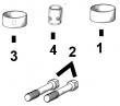
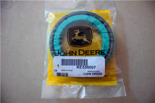
(1)1件组合式密封和穿套; 替换TRE59810,RE538097。
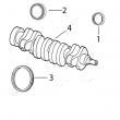
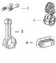
(2)在曲轴加工过程中必须保持正确的轴承轴颈半径,以确保正确操作。
(3)曲轴(m)R116076,直鼻。
(4)曲轴(m)R503470,锥形鼻。
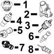
(5)检查应用程序是否正确使用。
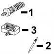
(6)线路连接都是线程化的。
(7)线路连接是一个软管倒钩& 一个线程。
(8)线路连接是两个软管倒钩。
(9)机器分体式和断裂式分体式连杆均可用于同一台发动机,但每个连杆必须使用正确的连杆螺栓。
强鹿JOHN DEERE柴油机配件、发动机配件、发电机组:
6090HFU75、6068HFU74、6090HFU84、4024TF220、6090HF485 6081HF001、6081AF001、6081TF001、4039DF004、6068HF252、4039DF005、4039DF008、6076TF010、6059TF001、4045HF275、RG6125、6135H458、4045DFM70, 4045TFM75
强鹿JOHN DEERE柴油机配件、发动机配件、发电机组:
6068TFM75, 6068TFM76、6068HF275、6125HF070\6125AF001,4039DFM、6125HF070、6135HF475-2、6135HF475-3 RE68345、 RE53307、RE62240、RE533095、RE502513、RE38009、R30402、RE517180、RE530107、RE62240、P524837、RE60021、RE507236、RE59588、RE549153、RE530870、SE501610、SE501609、RE70960、RE533501、RE533608、AR50041、RE515409
fan/acces***ies like air compres*** all power ratings are at full load at rated speed ctm104 (11jul02) 06-210-2 powertech? 4 5 l & 6 8 l diesel engines 071102 pn=604 continued on next page diagnostic specifications 06 210 3 rg,100,jw7641 –19–11jun02–3/13 power ratings on dynamometer for oem enginesa electronic original replaced by rated engine model software injection injection speed at power (emission fuel system option pump (part pump (part governor full load fast idle rating kw certification) option code codes no ) no ) regulation (rpm)a (rpm)a (hp)b 16bg re502712 std 2500 2700 63 (85) 16bh re500873 re502715 std 2500 2700 63 (85) 16bh re502715 std 2500 2700 63 (85) 16bj re500589 std 2250 2450 36 (48) 16cl re501364 re502713 std 2200 2400 58 (78) 16cl re502713 std 2200 2400 58 (78) re505803 std 2300 2500 60 (80) 16dl re70452 std 2400 2600 61 (82) 16en re502019 std 2500 2700 60 (80) 16gb re502711 std 2500 2700 60 (80) 16gc re502716 std 2500 2700 60 (80) 16hj re500948 std 2500 2700 60 (80) 16hk re500949 std 2500 2700 60 (80) 16hv re503258 std 2250 2450 36 (48) 16ke re503560 std 2500 2700 52 (70) 16lm re502711 std 2500 2700 53 (71) 16ln re67558 re505070 3—5% 1800 1870 53 (71) 16ln re505070 re506132 3—5% 1800 1870 53 (71) 16ln re506132 3—5% 1800 1870 53 (71) 16rb re503729 3—5% 1500 1560 44 (59) 16rc re504693 3—5% 1500 1560 44 (59) 4045df151 1663 re71089 re500949 std 2500 2700 60 (80) (tier i) 1663 re500949 std 2500 2700 60 (80) 4045df152 1601 re67557 std 2500 2700 60 (80) (tier i) 16gb re502711 std 2500 2700 60 (80) 4045df153 16ay re500505 std 2400 2600 62 (83) (tier i) 4045df154 16ay re500505 std 2400 2600 62 (83) (tier i) 16js re500505 std 2400 2600 62 (83) 4045df157 16aa re503729 3—5% 1500 1560 44 (59) (tier i) 16bb re504693 3—5% 1500 1560 44 (59) 4045df158 1673 re67560 3—5% 1800 1870 53 (71) (tier i) 1674 re67561 3—5% 1800 1870 53 (71) 16aa re503729 3—5% 1500 1560 44 (59) 16bb re504693 3—5% 1500 1560 44 (59) aengine speeds listed are preset to factory specifications slow idle speed may be reset depending upon specific vehicle application requirements refer to your machine operator’s manual for engine speeds that are different from those preset at the factory bpower ratings are for a bare engine without drag of cooling fan/acces***ies like air compres*** all power ratings are at full load at rated speed ctm104 (11jul02) 06-210-3 powertech? 4 5 l & 6 8 l diesel engines 071102 pn=605 continued on next page diagnostic specifications 06 210 4 rg,100,jw7641 –19–11jun02–4/13 power ratings on dynamometer for oem enginesa electronic original replaced by rated engine model software injection injection speed at power (emission fuel system option pump (part pump (part governor full load fast idle rating kw certification) option code codes no ) no ) regulation (rpm)a (rpm)a (hp)b 16cc re503731 3—5% 1800 1870 53 (71) 16dd re504694 3—5% 1800 1870 53 (71) 4045dfm50 16hr re503164 std 2500 2700 63 (85) (non—certified marine) 16hs re503165 std 2500 2700 63 (85) 16ht re503166 3—5% 1800 1870 48 (64) 16hu re503167 3—5% 1800 1870 48 (64) 4045tf120 (non—certified) 16mt re503733 3—5% 1500 1560 70 (94) 16mu re505050 3—5% 1500 1560 70 (94) 4045tf150 86 (115) (tier i) 1605 re69781 std 2500 2700 1656 re67562 3—5% 1800 75 (101) 1675 re69782 std 2500 2700 86 (115) 1676 re60093 std 2500 2700 86 (115) 1677 re60096 re67563 3—5% 1800 1870 75 (101) 1677 re67563 3—5% 1800 1870 75 (101) 1692 re61668 re500881 std 2500 2700 86 (115) 1692 re500881 re502416 std 2500 2700 86 (115) 1692 re502416 std 2500 2700 86 (115) 1694 re67863 re69779 std 2500 2700 74 (99) 1694 re69779 std 2500 2700 74 (99) 1695 re69739 re69780 std 2500 2700 74 (99) 1695 re69780 std 2500 2700 74 (99) 16ab re69779 std 2500 2700 75 (101) 16bf re500848 std 2200 2400 73 (98) 16ce re501180 std 2500 2700 74 (99) 16cm re501365 std 2200 2400 66 (89) 16gl re502706 std 2300 2500 78 (105) 16lp re67562 3—5% 1800 1870 75 (101) 16lz re503735 3—5% 1800 1870‘ 70 (94) 16ma re504696 re504931 3—5% 1800 1870 82 (110) 16ma re504931 3—5% 1800 1870 82 (110) 16mt re503733 re505050 3—5% 1500 1560 70 (94) 16mt re505050 3—5% 1500 1560 70 (94) 16mu re504695 re505050 3—5% 1500 1560 70 (94) 16mu re505050 3—5% 1500 1560 70 (94) 16tg re507941 std 2000 2185 77 (103) 16yg re508834 std 2000 2185 77 (103) aengine speeds listed are preset to factory specifications slow idle speed may be reset depending upon specific vehicle application requirements refer to your machine operator’s manual for engine speeds that are different from those preset at the factory bpower ratings are for a bare engine without drag of cooling fan/acces***ies like air compres*** all power ratings are at full load at rated speed ctm104 (11jul02) 06-210-4 powertech? 4 5 l & 6 8 l diesel engines 071102 pn=606 continued on next page diagnostic specifications 06 210 5 rg,100,jw7641 –19–11jun02–5/13 power ratings on dynamometer for oem enginesa electronic original replaced by rated engine model software injection injection speed at power (emission fuel system option pump (part pump (part governor full load fast idle rating kw certification) option code codes no ) no ) regulation (rpm)a (rpm)a (hp)b 4045tf151 (tier i) 1677 re67563 3—5% 1800 1870 75 (101) 16cu re501192 std 2200 2400 79 5 (107) 16nh re505411 3—5% 1800 2240 75 (101) 4045tf152 (tier i) 16ax re500551 std 2400 2600 76 (102) 4045tf154 1605 re69781 std 2500 2700 86 (115) (tier i) 4045tf155 16ax re500551 std 2400 2600 76 (102) (tier i) 16jt re500551 std 2400 2600 76 (102) 4045tf157 16gq re503048 3—5% 1500 1560 83 (111) (tier i) 16lv re503830 3—5% 1500 1560 83 (111) 4045tf158 16gq re503048 3—5% 1500 1560 83 (111) (tier i) 16lz re503735 3—5% 1800 1870 82 (110) 16ma re504696 3—5% 1800 1870 82 (110) 16mt re503733 3—5% 1500 1560 70 (94) 16mu re504695 re505050 3—5% 1500 1560 70 (94) 16mu re505050 3—5% 1500 1560 70 (94) 4045tf161 16pz re500848 std 2200 2400 73 (98) (non—certified) 4045tf162 16tg re507941 std 2000 2170 77 (103) (non—certified) 4045tf220 16gq re503048 3—5% 1500 1560 83 (111) (non—certified) 16lv re503830 3—5% 1500 1560 83 (111) 16mv re503736 3—5% 1800 1870 100 (134) 16mw re505051 3—5% 1800 1870 100 (134) 16nt re504465 std 2500 2700 86 (115) 16nu re504466 std 2500 2700 86 (115) 4045tf250 1606 re64133 std 2400 2600 93 (125) (tier i) 1608 re67564 3—5% 1800 1870 84 (113) 1667 re59968 std 2400 2600 93 (125) 1682 re67566 3—5% 1800 1870 84 (113) 1683 re60124 std 2400 2600 93 (125) 160r re70941 3—5% 1800 1870 84 (113) 16cv re501346 std 2200 2400 85 (114) aengine speeds listed are preset to factory specifications slow idle speed may be reset depending upon specific vehicle application requirements refer to your machine operator’s manual for engine speeds that are different from those preset at the factory bpower ratings are for a bare engine without drag of cooling fan/acces***ies like air compres*** all power ratings are at full load at rated speed ctm104 (11jul02) 06-210-5 powertech? 4 5 l & 6 8 l diesel engines 071102 pn=607 continued on next page diagnostic specifications 06 210 6 rg,100,jw7641 –19–11jun02–6/13 power ratings on dynamometer for oem enginesa electronic original replaced by rated engine model software injection injection speed at power (emission fuel system option pump (part pump (part governor full load fast idle rating kw certification) option code codes no ) no ) regulation (rpm)a (rpm)a (hp)b 16gq re503048 3—5% 1500 1560 83 (111) 16lq re67564 3—5% 1800 1870 84 (113) 16lv re503830 3—5% 1500 1560 83 (111) 16mb re503737 3—5% 1800 1870 91(122) 16mc re504932 3—5% 1800 1870 91 (122) 161c re507525 3—5% 1800 1870 100 (134) 161d re507526 3—5% 1800 1870 100 (134) 4045tf251 1606 re64133 std 2400 2600 93 (125) (tier i) 4045tf253 16te re507257 std 2400 2600 85 (114) (tier i) 4045tf257 16gq re503048 3—5% 1500 1560 83 (111) (tier i) 16lv re503830 3—5% 1500 1560 83 (111) 4045tf258 16gq re503048 3—5% 1500 1560 83 (111) (tier i) 16lv re503830 3—5% 1500 1560 83 (111) 16mb re503737 3—5% 1800 1870 91 (122) 16mc re504932 3—5% 1800 1870 91 (122) 16mv re503736 3—5% 1800 1870 100 (134) 16mw re504682 3—5% 1800 1870 100 (134) 4045tf275 161k, 163h (tier ii) (12v) 7288 re515464 electronic 2500 2700 86 (115) 161l, 163l (24v) 7289 re515464 electronic 2500 2700 86 (115) 161k, 163h (12v) 7290 re515464 electronic 2400 2600 82 (110) 161l, 163l (24v) 7291 re515464 electronic 2400 2600 82 (110) 161k, 163h (12v) 7292 electronic 1800 1870 84 (112) 161l, 163l (24v) 7293 electronic 1800 1870 84 (112) 4045tfm50 (non—certified marine) 16hm re503163 3—5% 1800 1870 71 (95) 16hn re503162 3—5% 1800 1870 71 (95) 16hp re503861 std 2500 2700 101 (135) 16hq re503860 std 2500 2700 101 (135) 16lk re503160 std 2600 2800 112 (150) 16ll re503161 std 2600 2800 112 (150) aengine speeds listed are preset to factory specifications slow idle speed may be reset depending upon specific vehicle application requirements refer to your machine operator’s manual for engine speeds that are different from those preset at the factory bpower ratings are for a bare engine without drag of cooling fan/acces***ies like air compres*** all power ratings are at full load at rated speed ctm104 (11jul02) 06-210-6 powertech? 4 5 l & 6 8 l diesel engines 071102 pn=608 continued on next page diagnostic specifications 06 210 7 rg,100,jw7641 –19–11jun02–7/13 power ratings on dynamometer for oem enginesa electronic original replaced by rated engine model software injection injection speed at power (emission fuel system option pump (part pump (part governor , full load fast idle rating kw certification) option code codes no ) no ) regulation (rpm)a (rpm)a (hp)b 4045hf120 (non—certified) 16gr re503050 3—5% 1500 1560 102 (137) 16lw re503832 3—5% 1500 1560 102 (137) 4045hf150 (tier i) 1610 re68826 std 2400 2600 104 (140) 1611 re60237 3—5% 1800 1870 95 (127) 160b re68827 3—5% 1800 1870 95 (127) 160c re69588 std 2400 2600 104 (140) 16gr re503050 3—5% 1500 1560 100 (134) 16lw re503832 3—5% 1500 1560 100 (134) 16qz re503050 3—5% 1800 1870 111 (149) 16ra re503832 3—5% 1800 1870 111 (149) 4045hf152 (tier i) 16rm re505959 std 2400 2600 104 (140) 4045hf157 (tier i) 16gr re503050 3—5% 1500 1560 100 (134) 16lw re503832 3—5% 1500 1560 100 (134) 4045hf158 (tier i) 16gr re503050 3—5% 1500 1560 100 (134) 16lw re503832 3—5% 1500 1560 100 (134) 16me re503739 3—5% 1800 1870 123 (170) 16mf re504698 re504966 3—5% 1800 1870 123 (170) 16mf re504966 3—5% 1800 1870 123 (170) 4045hf275 161f, 163g (tier ii) (12v) 7262 re507968 electronic 2400 2600 104 (140) 161g, 163k (24v) 7263 re507968 electronic 2400 2600 104 (140) 161f, 163g (12v) 7264 re507968 electronic 2400 2600 93 (125) 161g, 163k (24v) 7265 re507968 electronic 2400 2600 93 (125) 161f, 163g (12v) 7266 re507968 electronic 2200 2400 93 (125) 161g, 163k (24v) 7267 re507968 electronic 2200 2400 93 (125) 161f, 163g (12v) 7268 re507968 electronic 2000 2100 86 (115) 161g, 163k (24v) 7269 re507968 electronic 2000 2100 86 (115) 161f, 163g (12v) 7270 re507968 electronic 1800 1870 108 (145) aengine speeds listed are preset to factory specifications slow idle speed may be reset depending upon specific vehicle application requirements refer to your machine operator’s manual for engine speeds that are different from those preset at the factory bpower ratings are for a bare engine without drag of cooling fan/acces***ies like air compres*** all power ratings are at full load at rated speed ctm104 (11jul02) 06-210-7 powertech? 4 5 l & 6 8 l diesel engines 071102 pn=609 continued on next page diagnostic specifications 06 210 8 rg,100,jw7641 –19–11jun02–8/13 power ratings on dynamometer for oem enginesa electronic original replaced by rated engine model software injection injection speed at power (emission fuel system option pump (part pump (part governor full load fast idle rating kw certification) option code codes no ) no ) regulation (rpm)a (rpm)a (hp)b 161g, 163k (24v) 7271 re507968 electronic 1800 1870 108 (145) 161f, 163g (12v) 7272 re507968 electronic 1800 1870 117 (157) 161g, 163k (24v) 7273 re507968 electronic 1800 1870 117 (157) 4045hf475 (4-valve) (tier ii) 161v (12v) 72at electronic 2400 2600 129 (173) 161v (12v) 72au electronic 2200 2400 119 (160) 161v (12v) 72av electronic 1800 1870 143 (192) 161v (12v) 72aw electronic 1500 1560 120 (161) 6068df150 1613 re59861 std 2500 2700 93 (125) (tier i) 1678 re60101 std 2500 2700 93 (125) 16lr re59861 std 2500 2700 93 (125) 6068tf120 16mx re503740 3—5% 1500 1560 105 (141) (non—certified) 16my re505052 3—5% 1500 1560 105 (141) 6068tf150 1614 re61669 re69789 std 2500 2700 127 (170) (tier i) 1614 re69789 std 2500 2700 127 (170) 1680 re60105 re69790 std 2500 2700 127 (170) 1680 re69790 std 2500 2700 127 (170) 1681 3—5% 1500 1560 104 (139) 1681 re67571 3—5% 1800 1870 112 (150) 1688 re67572 3—5% 1800 1870 112 (150) 1696 re67864 re69787 std 2500 2700 116 (155) 1696 re69787 std 2500 2700 116 (155) 1697 re68740 re69788 std 2500 2700 116 (155) 1697 re69788 std 2500 2700 116 (155) 16be re63559 re501302 std 2200 2400 117 (157) 16be re501302 std 2200 2400 117 (157) 16cn re501522 re509681 std 2100 2300 110 5 (148) 16ls re67572 3—5% 1500 1560 94 (126) 16cp re501523 std 2200 2400 94 (126) 16dk re70938 std 2100 2300 96 (129) 16dy re501758 std 2500 2700 116 (155) 16gm re502693 std 2300 2500 110 (148) 16gn re502704 std 2400 2600 116 (155) 16ls re67572 3—5% 1800 1870 112 (150) aengine speeds listed are preset to factory specifications slow idle speed may be reset depending upon specific vehicle application requirements refer to your machine operator’s manual for engine speeds that are different from those preset at the factory bpower ratings are for a bare engine without drag of cooling fan/acces***ies like air compres*** all power ratings are at full load at rated speed ctm104 (11jul02) 06-210-8 powertech? 4 5 l & 6 8 l diesel engines 071102 pn=610 continued on next page diagnostic specifications 06 210 9 rg,100,jw7641 –19–11jun02–9/13 power ratings on dynamometer for oem enginesa electronic original replaced by rated engine model software injection injection speed at power (emission fuel system option pump (part pump (part governor full load fast idle rating kw certification) option code codes no ) no ) regulation (rpm)a (rpm)a (hp)b 16mg re503742 3—5% 1800 1870 123 (165) 16mh re504967 3—5% 1800 1870 123 (165) 6068tf151 1681 re67571 re505358 3—5% 1800 1870 112 (150) (tier i) 1681 re505358 3—5% 1800 2240 112 (150) 1696 re69787 std 2500 2700 116 (155) 16nj re505358 3—5% 1800 1870 112 (150) 6068tf152 1696 re69787 std 2500 2700 116 (155) (tier i) 16ju re69787 std 2500 2700 116 (155) 6068tf157 16gs re503049 3—5% 1500 1560 120 (161) (tier i) 16lx re503834 3—5% 1500 1560 120 (161) 6068tf158 16gs re503049 3—5% 1500 1560 120 (161) (tier i) 16jv re503872 3—5% 1500 1560 100 (134) 16jw re503874 3—5% 1500 1560 100 (134) 16mg re503742 3—5% 1800 1870 123 (165) 16mh re504966 re504967 3—5% 1800 1870 123 (165) 16mh re504967 3—5% 1800 1870 123 (165) 16mx re503740 3—5% 1500 1560 105 (141) 16my re504699 re505052 3—5% 1500 1560 105 (141) 16my re505052 3—5% 1500 1560 105 (141) 6068tf159 16pd re70938 std 2100 2250 96 (129) (tier i) 6068tf220 16gs re503045 3—5% 1500 1560 121 (162) (non—certified) 16kk re502694 std 2500 2700 127 (170) 16lx re503836 3—5% 1500 1560 121 (162) 16rk re506083 3—5% 2600 2700 138 (185) 16rj re506084 3—5% 2100 2200 172 (231) 16sg re506625 3—5% 2100 2200 172 (231) 16sh re506626 3—5% 2600 2700 138 (185) 16zl re509424 3—5% 2100 2200 172 (128) 16zm re509425 3—5% 2100 2200 172 (128) 16zn re509426 std 2600 2800 138 (103) 16zp re509427 std 2600 2800 138 (103) 6068tf250 1615 re62366 re69791 std 2400 2600 138 (185) (tier i) 1615 re69791 std 2400 2600 138 (185) aengine speeds listed are preset to factory specifications slow idle speed may be reset depending upon specific vehicle application requirements refer to your machine operator’s manual for engine speeds that are different from those preset at the factory bpower ratings are for a bare engine without drag of cooling fan/acces***ies like air compres*** all power ratings are at full load at rated speed ctm104 (11jul02) 06-210-9 powertech? 4 5 l & 6 8 l diesel engines 071102 pn=611 continued on next page diagnostic specifications 06 210 10 rg,100,jw7641 –19–11jun02–10/13 power ratings on dynamometer for oem enginesa electronic original replaced by rated engine model software injection injection speed at power (emission fuel system option pump (part pump (part governor full load fast idle rating kw certification) option code codes no ) no ) regulation (rpm)a (rpm)a (hp)b 1619 re67573 3—5% 1800 1870 124 (166) 1668 re59969c std 2400 2600 138 (185) 1685 re67574 3—5% 1800 1870 124 (166) 1686 re60131 re69792 std 2400 2600 138 (185) 1686 re69792 std 2400 2600 138 (185) 16cw re501344 std 2200 2400 106 (142) 16cx re70390 std 2300 2500 128 (172) 16gs re503049 3—5% 1500 1560 120 (161) 16lt re69791 std 2400 2600 138 (185) 16lu re67573 3—5% 1800 1870 124 (166) 16lx re503834 3—5% 1500 1560 120 (161) 16mj re503744 3—5% 1800 1870 142 (190) 16mk re504701 re504968 3—5% 1800 1870 142 (190) 16mk re504968 3—5% 1800 1870 142 (190) 16ug re506956 std 2400 2600 149 (200) 6068tf251 1615 re62366 std 2400 2600 138 (185) (tier i) 6068tf257 16gs re503049 3—5% 1500 1560 120 (161) (tier i) 16lx re503834 3—5% 1500 1560 120 (161) 6068tf258 16gs re503049 3—5% 1500 1560 120 (161) (tier i) 16lx re503834 3—5% 1500 1560 120 (161) 16mj re503744 3—5% 1800 1870 142 (190) 16mk re504701 re504968 3—5% 1800 1870 142 (190) 16mk re504968 3—5% 1800 1870 142 (190) 6068tf275 161j, 163m 72aa re515679 electronic 2400 2600 123 (165) (tier ii) (24v) 161h, 163f 72ab re515679 electronic 2200 2400 101 (135) (12v) 161j, 163m 72ac re515679 electronic 2200 2400 101 (135) (24v) 161h, 163f 72ad re515679 electronic 2200 2400 112 (150) (12v) 161j, 163m 72ae re515679 electronic 2200 2400 112 (150) (24v) 161h, 163f 72af re515679 electronic 2000 2100 104 (140) (12v) aengine speeds listed are preset to factory specifications slow idle speed may be reset depending upon specific vehicle application requirements refer to your machine operator’s manual for engine speeds that are different from those preset at the factory bpower ratings are for a bare engine without drag of cooling fan/acces***ies like air compres*** all power ratings are at full load at rated speed cin-line fuel injection pump ctm104 (11jul02) 06-210-10 powertech? 4 5 l & 6 8 l diesel engines 071102 pn=612 continued on next page diagnostic specifications 06 210 11 rg,100,jw7641 –19–11jun02–11/13 power ratings on dynamometer for oem enginesa electronic original replaced by rated engine model software injection injection speed at power (emission fuel system option pump (part pump (part governor full load fast idle rating kw certification) option code codes no ) no ) regulation (rpm)a (rpm)a (hp)b 161j, 163m 72ag (24v) re515679 electronic 2000 2100 104 (140) 161h, 163f 72ah (12v) re515679 electronic 1800 1870 123 (165) 161j, 163m 72aj (24v) re515679 electronic 1800 1870 123 (165) 161h, 163f 7294 (12v) re515679 electronic 2500 2700 116 (155) 161j, 163m 7295 (24v) re515679 electronic 2500 2700 116 (155) 161h, 163f 7296 (12v) re515679 electronic 2500 2700 127 (170) 161j, 163m 7297 (24v) re515679 electronic 2500 2700 127 (170) 161h, 163f 7298 (12v) re515679 electronic 2400 2600 123 (165) 6068tfm50 16fa re502619 std 2600 2800 168 (225) (non—certified marine) 16fb re502620 std 2600 2800 168 (225) 16fc re502621 std 2400 2600 130 (175) 16fd re502622 std 2400 2600 130 (175) 16fe re502623 3—5% 1800 1870 115 (154) 16ff re502624 3—5% 1800 1870 115 (154) 6068sfm50 161e (7238), electronic 2600 2700 224 (300) (non-certified 162k (7247) marine) 161e (7248), electronic 2500 2600 198 (266) 162k (7249) 161e (7250), electronic 2400 2500 175 (235) 162k (7251) 161e (7252), electronic 2300 2400 153 (205) 162k (7253) 161e (7254), electronic 2200 2300 134 (180) 162k (7255) 6068hf120 16gt re503051 3—5% 1500 1560 155 (208) (non—certified) 16ly re503834 3—5% 1500 1560 155 (208) 16rl re506085 3—5% 2100 2200 197 (264) 16sj re506627 3—5% 2100 2200 197 (264) aengine speeds listed are preset to factory specifications slow idle speed may be reset depending upon specific vehicle application requirements refer to your machine operator’s manual for engine speeds that are different from those preset at the factory bpower ratings are for a bare engine without drag of cooling fan/acces***ies like air compres*** all power ratings are at full load at rated speed ctm104 (11jul02) 06-210-11 powertech? 4 5 l & 6 8 l diesel engines 071102 pn=613 continued on next page diagnostic specifications 06 210 12 rg,100,jw7641 –19–11jun02–12/13 power ratings on dynamometer for oem enginesa electronic original replaced by rated engine model software injection injection speed at power (emission fuel system option pump (part pump (part governor full load fast idle rating kw certification) option code codes no ) no ) regulation (rpm)a (rpm)a (hp)b 16tp re506883 3—5% 1500 1560 183 (245) 16tq re506884 3—5% 1500 1560 183 (245) 16zq re509428 3—5% 2100 2200 197 (264) 16zr re509429 3—5% 2100 2200 197 (264) 6068hf150 (tier i) 1621 re66575 std 2400 2600 157 (210) 160d re69589 std 2400 2600 157 (210) 16cy re501345 std 2200 2400 143 (192) 16gt re503051 3—5% 1500 1560 153 (205) 16ly re503836 3—5% 1500 1560 153 (205) 16ml re503746 3—5% 1800 1870 187 (251) 16mm re504702 re505049 3—5% 1800 1870 187 (251) 16mm re505049 3—5% 1800 1870 187 (251) 16qv re503051 3—5% 1800 1870 166 (223) 16qw re503836 3—5% 1800 1870 166 (223) 1623 3—5% 1500 1560 123 (165) 6068hf157 (tier i) 16gt re503051 3—5% 1500 1560 153 (205) 16ly re503836 3—5% 1500 1560 153 (205) 6068hf158 (tier i) 16gt re503051 3—5% 1500 1560 153 (205) 16ly re503836 3—5% 1500 1560 153 (205) 16ml re503746 3—5% 1800 1870 187 (251) 16mm re504702 re505049 3—5% 1800 1870 187 (251) 16mm re505049 3—5% 1800 1870 187 (251) 6068hf250 (tier i) 1622 re59521c std 2400 2600 168 (225) 1623 re66761c 3—5% 1800 1870 148 (198) 16yh re59969 std 2400 2605 138 (185) 6068hf275 7201 (tier ii) 16ys (12v) re506680 electronic 2400 2600 168 (225) 16yt (24v) 7202 re506681 electronic 2400 2600 168 (225) 16ys (12v) 7203 re506680 electronic 2400 2600 149 (200) 16yt (24v) 7204 re506681 electronic 2400 2600 149 (200) 16ys (12v) 7205 re506680 electronic 2400 2600 138 (185) 16yt (24v) 7206 re506681 electronic 2400 2600 138 (185) 16ys (12v) 7207 re506680 electronic 2200 2400 149 (200) 16yt (24v) 7208 re506681 electronic 2200 2400 149 (200) aengine speeds listed are preset to factory specifications slow idle speed may be reset depending upon specific vehicle application requirements refer to your machine operator’s manual for engine speeds that are different from those preset at the factory bpower ratings are for a bare engine without drag of cooling fan/acces***ies like air compres*** all power ratings are at full load at rated speed cin-line fuel injection pump ctm104 (11jul02) 06-210-12 powertech? 4 5 l & 6 8 l diesel engines 071102 pn=614 continued on next page diagnostic specifications 06 210 13 rg,100,jw7641 –19–11jun02–13/13 power ratings on dynamometer for oem enginesa electronic original replaced by rated engine model software injection injection speed at power (emission fuel system option pump (part pump (part governor full load fast idle rating kw certification) option code codes no ) no ) regulation (rpm)a (rpm)a (hp)b 16ys (12v) 7274 re506680 electronic 2400 2600 187 (250) 16yt (24v) 7275 re506681 electronic 2400 2600 187 (250) 16ys (12v) 7276 re508732 electronic 2200 2400 168 (225) 16yt (24v) 7277 re508732 electronic 2200 2400 168 (225) 16ys (12v) 7278 re508732 electronic 2000 2100 157 (210) 16yt (24v) 7279 re508732 electronic 2000 2100 157 (210) 161n, 163e 7280 (12v) re508732 electronic 2000 2100 129 (173) 161q, 163j 7281 (24v) re508732 electronic 2000 2100 129 (173) 161n, 163e 7282 (12v) re508732 electronic 1800 1870 164 (220) 161q, 163j 7283 (24v) re508732 electronic 1800 1870 164 (220) 16ys (12v) 7284 re506680 electronic 1800 1870 187 (250) 16yt (24v) 7285 re506681 electronic 1800 1870 187 (250) 16ys, 162b 7286 (12v) re508732 electronic 1800 1870 210 (282) 16yt, 162c 7287 (24v) re508732 electronic 1800 1870 210 (282) 6068hf475 72ap (4-valve) (tier ii) 161u (12v) electronic 2400 2600 205 (275) 161u (12v) 72aq electronic 2200 2400 187 (250) 161u (12v) 72ar electronic 1800 1870 234 (314) 161u (12v) 72as electronic 1500 1560 207 (278) aengine speeds listed are preset to factory specifications slow idle speed may be reset depending upon specific vehicle application requirements refer to your machine operator’s manual for engine speeds that are different from those preset at the factory bpower ratings are for a bare engine without drag of cooling fan/acces***ies like air compres*** all power ratings are at full load at rated speed ctm104 (11jul02) 06-210-13 powertech? 4 5 l & 6 8 l diesel engines 071102 pn=615 diagnostic specifications 06 210 14 dpsg,ouo1004,2748 –19–11jun02–1/24 intake manifold pressure (turbocharger boost) specifications note: this test of turbocharger boost is a good indicator of whether a turbocharged engine is performing at its full rated power for test procedure, see measure intake manifold pressure (turbocharger boost/pressure check) in group 150 power ratings specify flywheel power for a bare engine without the drag effect of a cooling fan or other acces***ies like an air compres*** altitude, fuel temperature, air temperature, and humidity may affect engine performance see effects of altitude&temperature on engine performance later in this group some specifications were not available at time of printing turbo boost pressures (john deere agricultural equipment) machine model engine model rated power at full load rated turbo boost pressure at full load rated full load rated speed speed speed rpm kpa (bar) (psi) kw (hp) des moines, iowa 4700/4710 sprayer t06068tn050 138 (185) 2400 113—137 kpa (1 1—1 4 bar) (16—20 psi) pe6068tn050 138 (185) 2400 113—137 kpa (1 1—1 4 bar) (16—20 psi) pe6068tn053 138 (185) 2400 144—176 kpa (1 4—1 8 bar) (21—25 psi) t06068tn053 138 (185) 2400 144—176 kpa (1 4—1 8 bar) (21—25 psi) pe6068tn052 149 (200) 2400 144—176 kpa (1 4—1 8 bar) (21—25 psi) 4720 sprayer pe6068hn051 168 (225) 2400 not available 6700 sprayer t04045tn050 79 (106) 2200 72—88 kpa (0 7—0 9 bar) (10—13 psi) pe4045tn050 79 (106) 2200 72—88 kpa (0 7—0 9 bar) (10—13 psi) 7455 cotton stripper t06068tn051 117 (157) 2200 79—97 kpa (0 8—1 0 bar) (12—14 psi) pe6068tn051 117 (157) 2200 79—97 kpa (0 8—1 0 bar) (12—14 psi) 7460 cotton stripper pe6068tn054 129 (173) 2200 not available 9935 cotton picker t06068tn051 117 (157) 2200 79—97 kpa (0 8—1 0 bar) (12—14 psi) pe6068tn051 117 (157) 2200 79—97 kpa (0 8—1 0 bar) (12—14 psi) east moline, illinois 9400 combine t06068hh050 138 (185) 2200 93—113 kpa (0 9—1 1 bar) (14—16 psi) 9410 combine t06068hh051 143 (192) 2200 94—116 kpa (0 9—1 2 bar) (14—17 psi) 9450 combine t06068hh052 143(192) 2200 85—105 kpa (0 9—1 1 bar) (13—16 psi) ctm104 (11jul02) 06-210-14 powertech? 4 5 l & 6 8 l diesel engines 071102 pn=616 continued on next page diagnostic specifications 06 210 15 dpsg,ouo1004,2748 –19–11jun02–2/24 turbo boost pressures (john deere agricultural equipment) machine model engine model rated power at full load rated turbo boost pressure at full load rated full load rated speed speed speed rpm kpa (bar) (psi) kw (hp) pe6068hh052 143 (192) 2200 85—105 kpa (0 9—1 1 bar) (13—16 psi) 9550cws combine pe6068hh054 129 (173) 2400 not available (low power) 9550cws combine pe6068hh055 136 (183) 2400 not available (high power) horizontina, brazil 1170 combine cd6068tcq50 133 (178) 2200 95—117 kpa (1 0—1 2 bar) (14—17 psi) 1450 combine j06068tcq04 162 (217) 2400 not available 1450cws combine cd6068hcq60 162 (217) 2400 107—131 kpa (1 1—1 3 bar) (16—19 psi) 1550 combine j06068acq01 181 (243) 2400 not available 1550cws combine cd6068hcq61 182 (244) 2400 130—160 kpa (1 3—1 6 bar) (19—23 psi) cd6068hcq61 173 (129) 2400 127—155 kpa (, 1 3—1 6 bar) (19-23 psi) 6400 tractor j04045tcq01 79 5 (107) 2300 not available 6600 tractor j06068tcq07 88 5 (119) 2300 not available 7500 tractor j06068tcq08 103 5 (139) 2100 not available jiamusi, china 1065 combine cd4045tyc50 86 (115) 2500 87—106 kpa (0 9—1 1 bar) (13—16 psi) 1075 combine cd6068tyc50 117 (157) 2200 airesearch/garrett turbo: 92—112 kpa (0 9— 1 1 bar) (13—16 psi) borg warner/schwitzer turbo: 101—123 kpa (1 0—1 2 bar) (15—18 psi) 3518 combine cd6068tyc51 149 (200) 2400 airesearch/garrett turbo: 142—174 kpa (1 4—1 7 bar) (21—25 psi) borg warner/schwitzer turbo: 161—197 kpa (1 6—2 0 bar) (23—29 psi) cd6068hyc50 160 (215) 2400 106—130 kpa (1 1—1 3 bar) (15—18 psi) zweibrucken, germany 2254 combine cd6068hz050 144 (193) 2200 94—116 kpa (0 9—1 2 bar) (14—17 psi) 3200/3400 tele handler cd4045tz250 79 5 (106 5) 2200 68—82 kpa (0 7—0 8 bar) (10—12 psi) 3700 tele handler, cd4045tz060 71 5 (96) 2200 not available articulated 3800 tele handler, cd4045hz050 86 (115) 2200 81—99 kpa (0 9—1 0 bar) (12—14 psi) articulated 9540/9540 hillmaster cd6068hz060 162 (217) 2400 108—132 kpa (1 1—1 3 bar) (16—19 psi) combine ottumwa, iowa 4890 windrower t04045te050 75 (100 5) 2500 81—99 kpa (0 8—1 0 bar) (11—14 psi) pe4045te050 75 (100 5) 2500 81—99 kpa (0 8—1 0 bar) (11—14 psi) 4895 windrower t04045te051 136 (182) 2300 not available pe4045te051 136 (182) 2300 not available ctm104 (11jul02) 06-210-15 powertech? 4 5 l & 6 8 l diesel engines 071102 pn=617 continued on next page diagnostic specifications 06 210 16 dpsg,ouo1004,2748 –19–11jun02–3/24 turbo boost pressures (john deere agricultural equipment) machine model engine model rated power at full load rated turbo boost pressure at full load rated full load rated speed speed speed rpm kpa (bar) (psi) kw (hp) 4990 windrower t06068te050 128 (172) 2300 101—112 kpa (1 0—1 1 bar) (15—17 psi) pe6068te050 128 (172) 2300 101—112 kpa (1 0—1 1 bar) (15—17 psi) 4995 windrower pe6068te051 136 (182) 2300 not available waterloo, iowa 7210 (syncro plus) t06068trw53 71 (95) pto 2100 49—61 kpa (0 5—0 6 bar) (7—9 psi) tractor pe6068trw53 71 (95) pto 2100 49—61 kpa (0 5—0 6 bar) (7—9 psi) 7210 (power quad) t06068trw50 71 (95) pto 2100 49—61 kpa (0 5—0 6 bar) (7—9 psi) tractor pe6068trw50 71 (95) pto 2100 49—61 kpa (0 5—0 6 bar) (7—9 psi) 7220 tractor cd6068trw01 87 (105) 2300 61 kpa (0 6 bar) (9 psi) 7320 tractor cd6068hrw01 96 5 (129) 2300 60 kpa (0 6 bar) (9 psi) 7410 (syncro plus) t06068trw54 79 (105) pto 2100 58—70 kpa (0 6—0 7 bar) (8—10 psi) tractor pe6068trw54 79 (105) pto 2100 58—70 kpa (0 6—0 7 bar) (8—10 psi) 7410 (power quad) t06068trw51 79 (105) pto 2100 58—70 kpa (0 6—0 7 bar) (8—10 psi) tractor pe6068trw51 79 (105) pto 2100 58—70 kpa (0 6—0 7 bar) (8—10 psi) 7420 tractor cd6068hrw01 104 (139) 2100 64 kpa (0 6 bar) (9 psi) 7510 (power quad) t06068trw70 86 (115) pto 2100 65—79 kpa (0 6—0 8 bar) (9—11 psi) tractor pe6068trw70 86 (115) pto 2100 65—79 kpa (0 6—0 8 bar) (9—11 psi) 7520 tractor cd6068hrw01 115 5 (155) 2100 73 kpa (0 7 bar) (11 psi) 7610 tractor t06068trw52 90 (120) pto 2100 65—79 kpa (0 7—0 8 bar) (9—12 psi) pe6068trw52 90 (120) pto 2100 65—79 kpa (0 7—0 8 bar) (9—12 psi) t06068trw72 90 (120) pto 2100 70—85 kpa (0 7—0 9 bar) (10—12 psi) pe6068trw72 90 (120) pto 2100 70—85 kpa (0 7—0 9 bar) (10—12 psi) 7720 tractor pe6068hrw53 104 (140) pto 2100 not available (4-valve) 7820 tractor pe6068hrw58 116 (155) pto 2100 not available (4-valve) 7920 tractor pe6068hrw?? 127 (170) pto 2100 not available (4-valve) mannheim, germany (european market) 3410 tractor cd4045trt50 67 (90) 2350 70 5 kpa (0 7 bar) (10 psi) 6020 tractor cd4045dl070 not available not available not available 6110 tractor cd4045tl058 58 (79) 2300 51—63 kpa (0 5—0 6 bar) (7—9 psi) (direct fan drive) 6110 tractor cd4045tl050 59 (80) 2300 51—63 kpa (0 5—0 6 bar) (7—9 psi) (viscous fan drive) 6120 tractor cd4045tl070 63 (84) 2300 57—70 kpa (0 6—0 7 bar) (8—10 psi) ctm104 (11jul02) 06-210-16 powertech? 4 5 l & 6 8 l diesel engines 071102 pn=618 continued on next page diagnostic specifications 06 210 17 dpsg,ouo1004,2748 –19–11jun02–4/24 turbo boost pressures (john deere agricultural equipment) machine model engine model rated power at full load rated turbo boost pressure at full load rated full load rated speed speed speed rpm kpa (bar) (psi) kw (hp) 6120 tractor (premium) not available not available not available not available 6205 tractor cd4045tl064 78(105) 2300 68—83 kpa (0 7—0 8 bar) (10—12 psi) 6210 tractor cd4045tl059 65 (88) 2300 58—71 kpa (0 6—0 7 bar) (8—10 psi) (direct fan drive) 6210 tractor cd4045tl051 66 (90) 2300 58—71 kpa (0 6—0 7 bar) (8—10 psi) (viscous fan drive) 6215 tractor (advantage) cd4045tl072 87 (117) 2300 86—105 kpa (0 9—1 0 bar) (12—15 psi) cd4045tl071 69 (93) 2300 67—81 kpa (0 7—0 8 bar) (10—12 psi) 6220 tractor cd4045tl071 65 (87) 2300 69—84 kpa (0 7—0 8 bar) (10—12 psi) 6310 tractor cd4045tl060 73 (99) 2300 68—83 kpa (0 7—0 8 bar) (10—12 psi) (direct fan drive) 6310 tractor cd4045tl052 74 (100) 2300 68—83 kpa (0 7—0 8 bar) (10—12 psi) (viscous fan drive) 6310 tractor cd4045tla50 77 (103) 2300 68—83 kpa (0 7—0 8 bar) (10—12 psi) (ecu level 4) 6320 tractor cd4045hl072 77 (103) 2300 65—79 kpa (0 6—0 8 bar) (9—11 psi) cd4045hla70 77 (103) 2300 65—79 kpa (0 6—0 8 bar) (9—11 psi) cd4045hl472 77 (103) 2300 not available 6320 tractor (premium) cd4045hl472 77 (103) 2300 not available 6320se tractor cd4045tl073 77 (103) 2300 76—92 kpa (0 8—0 9 bar) (11—13 psi) cd4045hl270 77 (103) 2300 not available 6410 tractor cd4045tl061 76 (103) 2300 69—84 kpa (0 7—0 8 bar) (10—12 psi) (direct fan drive) 6410 tractor cd4045tl053 77 (105) 2300 69—84 kpa (0 7—0 8 bar) (10—12 psi) (viscous fan drive) 6410 tractor cd4045tla51 77 (103) 2300 69—84 kpa (0 7—0 8 bar) (10—12 psi) (ecu level 4) 6420 tractor cd4045hl070 84 (113) 2300 71—88 kpa (0 7—0 9 bar) (10—13 psi) cd4045hla72 84 (113) 2300 71—88 kpa (0 7—0 9 bar) (10—13 psi) cd4045hl473 84 (112) 2300 not available 6420 tractor (premium) cd4045hl473 84 (113) 2300 not available 6420s tractor cd4045hla73 92 (123) 2300 79—97 kpa (0 8—1 0 bar) (11—14 psi) cd4045hl474 92 (123) 2300 not available cd4045hl474 84/92 (112/123) 2300 not available 6420se tractor cd4045hl271 84 (112) 2300 not available 6520 tractor (premium) cd6068hl470 85 5 (115) 2300 not available 6520se tractor cd6068tl270 85 5 (115) 2300 not available 6610 tractor cd6068tl050 84 (114) 2300 49—61 kpa (0 5—0 6 bar) (7—9 psi) 6610 tractor cd6068tla50 88 (118) 2300 49—61 kpa (0 5—0 6 bar) (7—9 psi) (ecu level 4) ctm104 (11jul02) 06-210-17 powertech? 4 5 l & 6 8 l diesel engines 071102 pn=619 continued on next page diagnostic specifications 06 210 18 dpsg,ouo1004,2748 –19–11jun02–5/24 turbo boost pressures (john deere agricultural equipment) machine model engine model rated power at full load rated turbo boost pressure at full load rated full load rated speed speed speed rpm kpa (bar) (psi) kw (hp) 6620 tractor cd6068hl471 96 5 (129) 2300 not available cd6068hla70 96 5 (129) 2300 54—66 kpa (0 5—0 7 bar) (8—10 psi) 6810 tractor cd6068tl051 92 (125) 2100 67—82 kpa (0 7—0 8 bar) (10—12 psi) 6810 tractor cd6068tla51 96 (129) 2100 67—82 kpa (0 7—0 8 bar) (10—12 psi) (ecu level 4) 6820 tractor cd6068hla71 104 (139) 2100 58—70 kpa (0 6—0 7 bar) (8—10 psi) 6820 tractor (premium) cd6068hl472 104 (139) 2100 not available 6910 tractor cd6068tl052 99 (135) 2100 71—87 kpa (0 7—0 9 bar) (10—13 psi) cd6068tl054 107 (143) 2100 79—96 kpa (0 8—1 0 bar) (11—14 psi) 6910 tractor cd6068tla52 107 (143) 2100 58—70 kpa (0 6—0 7 bar) (8—10 psi) (ecu level 4) 6910s tractor cd6068tla53 115 (154) 2100 65—79 kpa (0 7—0 8 bar) (9—11 psi) (ecu level 4, boost) 6920 tractor cd6068hla72 115 5 (154) 2100 66—81 kpa (0 7—0 8 bar) (10—12 psi) 6920 tractor (premium) cd6068hl473 115 5 (154) 2100 not available 6920s tractor cd6068hla73 123 5 (166) 2100 73—89 kpa (0 7—0 9 bar) (11—13 psi) cd6068hl474 115 5/123 5 2100 not available (155/165) mannheim, germany (north american market) 6110/6110l tractor cd4045tl063 48 (65) pto 2300 54—67 kpa (0 5—0 7 bar) (8—10 psi) 6120 tractor cd4045tl070 84 (113) 2300 57—70 kpa (0 6—0 7 bar) (8—10 psi) 6210/6210l tractor cd4045tl054 54 (72) pto 2300 61—75 kpa (0 6—0 8 bar) (9—11 psi) 6220 tractor cd4045tl071 65 (87) 2300 69—84 kpa (0 7—0 8 bar) (10—12 psi) cd4045tl272 69 (93) 2300 not available 6310/6310l/6310s cd4045tl055 60 (80) pto 2300 72—88 kpa (0 7—0 9 bar) (10—13 psi) tractor 6320 tractor cd4045hl073 74 (99) 2300 64—78 kpa (0 6—0 8 bar) (9—11 psi) cd4045hla71 74 (99) 2300 60—74 kpa (0 6—0 7 bar) (9—11 psi) cd4045hl270 77 (103) 2300 not available 6320ivt tractor cd4045hl472 77 (103) 2300 not available (premium) (4-valve) 6403, 6405 tractor cd4045tl062 67 (90) pto 2300 72—88 kpa (0 7—0 9 bar) (10—13 psi) (advantage) 6410/6410l/6410s cd4045tl056 67 (90) pto 2300 84—102 kpa (0 8—1 0 bar) (12—15 psi) tractor 6415 tractor cd4045hl272 78 (105) 2300 not available 6415 tractor (advantage) cd4045tl075 78 (105) 2300 72—88 kpa (0 7—0 9 bar) (10—13 psi) 6420 tractor cd4045hl070 84 (113) 2300 71—88 kpa (0 7—0 9 bar) (10—13 psi) cd4045hla72 84 (113) 2300 71—88 kpa (0 7—0 9 bar) (10—13 psi) ctm104 (11jul02) 06-210-18 powertech? 4 5 l & 6 8 l diesel engines 071102 pn=620 continued on next page diagnostic specifications 06 210 19 dpsg,ouo1004,2748 –19–11jun02–6/24 turbo boost pressures (john deere agricultural equipment) machine model engine model rated power at full load rated turbo boost pressure at full load rated full load rated speed speed speed rpm kpa (bar) (psi) kw (hp) 6420ivt tractor cd4045hl473 84 (113) 2300 not available (premium) (4-valve) 6420se tractor cd4045hl271 84 (113) 2300 not available 6510l/6510s tractor cd4045tl057 71 (95) pto 2300 88—108 kpa (0 9—1 1 bar) (13—16 psi) 6520ivt tractor cd6068hl470 85 5 (115) 2300 not available (premium) (4-valve) 6520l tractor cd4045hl071 86 (115) 2300 73—90 kpa (0 7—0 9 bar) (11—13 psi) cd4045hl273 86 (115) 2300 not available 6603, 6605 tractor cd6068tl053 75 (100) pto 2300 49—60 kpa (0 5—0 6 bar) (7—9 psi) (advantage) 6615 tractor cd6068tl271 87 (116) 2300 not available 6615 tractor (advantage) cd6068tl071 87 (117) 2300 49—60 kpa (0 5—0 6 bar) (7—9 psi) 6620ivt tractor cd6068hl471 96 5 (129) 2300 not available (premium) (4-valve) 6820ivt tractor cd6068hl472 104 (140) 2100 not available (premium) (4-valve) 6920ivt tractor cd6068hl473 115 5 (155) 2100 not available (premium) (4-valve) saltillo, mexico 5715 tractor pe4045tp050 67 (90) 2400 54—66 kpa (0 5—0 7 bar) (8—10 psi) pe4045tp059 67 (90) 2400 48—59 kpa (0 5—0 6 bar) (7—9 psi) 6103 tractor pe4045tp055 64 (86) 2100 38—46 kpa (0 4—0 5 bar) (6—7 psi) 6203 tractor pe4045tp056 71 (95) 2100 67—82 kpa (0 7—0 8 bar) (10—12 psi) 6400 tractor pe4045tp054 78 (105) 2300 72—88 kpa (0 7—0 9 bar) (10—13 psi) 6403 tractor pe4045tp057 79 (106) 2100 72—88 kpa (0 7—0 9 bar) (10—13 psi) (non—certified) pe4045tp060 72 7 (98) 2100 55—67 kpa (0 5—0 7 bar) (8—10 psi) (tier i certified) 6415 tractor pe4045tp061 78 (105) 2300 not available 6603 tractor pe6068tp053 87 (117) 2100 36—44 kpa (0 4—0 5 bar) (6—7 psi) (non—certified) pe6068tp054 81 5 (109) 2100 40—50 kpa (0 4—0 5 bar) (6—7 psi) (tier i certified) 7320 tractor pe6068tp056 96 (129) 2300 not available 7405 tractor (advantage) cd6068tp051 96 (129) 2100 65—79 kpa (0 7—0 8 bar) (9—11 psi) 万州9Y-6826卡特滤清器认准指定代理商,黄冈罗田县P551551唐纳森滤清器一件代发,成都龙泉驿CAT卡特C6.6发动机滤清器芯哪家好?,湛江徐闻县卡特皮勒3512B备件供应服务商?,日照五莲县CATC2.2柴油机配件+维修技术支持一件代发,河北石家庄桥东珀金斯高压油泵2643D196去哪买?,渭南潼关县卡特彼勒发动机气缸垫的地方在那?,汕头澄海FGWilson发电机去哪买?求推荐,商洛镇安县康明斯发动机配件专营网批发,日喀则康马县TAD1231GE旁通滤费用报价单,宝鸡扶风县康明斯配件贵州的价格,河北廊坊三河卡特彼勒滤清器送货到家更快,六安寿县珀金斯404D-22柴油机代理商求推荐,银川兴庆卡特彼勒汽缸垫多少钱价格怎么样?,宜宾宜宾县帕金斯水温传感器求推荐,铜仁德江县PERKINS柴油发电机组控制器系统供应服务商?,oem engine acces***ies ctm67 24sep02 (english) component technical manual oem engine acces***ies technical manual oem engine acces***ies ctm67 24sep02 (english) john deere power systems litho in u.s.a. introduction rg,ctm67,ifc –19–02feb94–1/1 foreword this manual is written for an experienced technician. essential tools required in performing certain service work are identified in this manual&are recommended for use. live with safety: read the safety messages in the introduction of this manual&the cautions presented throughout the text of the manual. caution: this is the safety-alert symbol. when you see this symbol on the machine or in this manual, be alert to the potential for personal injury. this component technical manual (ctm) contains the latest available instructions necessary to repair oem engine acces***ies. it includes theory of operation, and diagnostic&testing procedures to help troubleshoot&understand potential failure modes. the information is organized in groups for the various components requiring service instruction. at the beginning of each repair group are summary listings of all applicable essential tools, service equipment and tools, other materials needed to do the job, service parts kits, specifications, wear tolerances,&torque values. component technical manuals are concise service guides for specific components. component technical manuals are written as stand-alone manuals covering multiple machine applications. fundamental service information is available from other sources covering basic theory of operation, fundamentals of troubleshooting, general maintenance, and basic types of failures&their causes. dpsg,ouo1004,769 –19–22may02–1/1 john deere dealers the changes listed below make your ctm obsolete. discard ctm 67 dated 16nov99&replace with this new manual. also, copy these pages&route through your service department. group 46—new ? added new group 46 covering new john deere rear pto removal, disassembly, reassembly&installation procedures. other groups—miscellaneous revisions ctm67 (24sep02) oem engine acces***ies 092402 pn=2 contents section —oem engine acces***ies group 05—safety group 10—general information group 20—electrical system information&wiring diagrams indx group 21—electrical system diagnostics, tests and operation group 22—electrical system repair and adjustments group 25—cold weather starting aids group 30—fuel system acces***ies group 31—utc electric/isochronous governor (8955 engines) group 32—electric fuel supply pump—8955 engines group 40—engine cooling system acces***ies group 45— rear pto - rockford/twin disc group 46—rear pto - john deere group 47—front pto group 50—auxiliary drive, 6076 (500000— ) group 51—auxiliary drive (2.9 l) group 52—auxiliary drive (4.5 l&6.8 l) group 53—auxiliary drive (8.1 l) group 54—auxiliary drive (10.5 l&12.5 l) group 60—air compres***s group 70—air conditioning compres***s all information, illustrations&specifications in this manual are based on the latest information available at the time of publication. the right is reserved to make changes at any time without notice. copyright ? 2002 deere & company moline, illinois all rights reserved a john deere illustruction? manual previous editions copyright ? 1994, 1999 ctm67 (24sep02) i oem engine acces***ies 092402 pn=1 contents indx ctm67 (24sep02) ii oem engine acces***ies 092402 pn=2 section oem engine acces***ies contents page page group 05—safety 05-1 engine wiring diagram - powertech 8.1 l, 10.5 l&12.5 l engines (with john group 10—general information deere ecu) (continued) 20-29 about this manual 10-1 engine wiring diagram legend—saran vdo unified inch bolt&cap screw torque instrument panel 20-30 values 10-2 engine wiring diagram—saran vdo metric bolt&cap screw torque values 10-3 instrument panel 20-31 engine wiring diagram—saran aez group 20—electrical system information&instrument panel 20-32 wiring diagrams electrical circuit malfunctions 20-1 group 21—electrical system diagnostics, tests high resistance circuit 20-2&operation open circuit 20-3 service equipment&tools 21-1 grounded circuit 20-5 electrical system specifications 21-1 shorted circuit 20-7 general information21-2 multimeter . 20-8 component function—instrument panel seven step electrical test procedure 20-9 (without ecu) 21-3 wiring diagram&schematic information20-11 component function—instrument panel reading a system functional schematic 20-13 (with lucas ecu) 21-6 reading a wiring diagram 20-14 component function—instrument panel electrical schematic symbols 20-15 (with john deere ecu) 21-8 component identification table 20-18 component function—saran vdo instrument engine wiring diagram legend—north panel 21-12 american series 300, 400, 500&700 component function—saran aez engines&early model european instrument panel 21-14 (saran) series 300 engines20-20 component function—crankcase oil level wiring diagram—north american series switch/gauge 21-16 300, 400&500 engines20-21 before you start diagnostics 21-17 wiring diagram—north american series 700 visually inspect electrical system 21-18 (8955) engines 20-22 diagnose electrical system malfunctions 21-19 wiring diagram—european (saran) series checking fuses in instrument panels 21-21 300 engines (early model)20-23 test key switch 21-24 engine wiring diagram legend - powertech test magnetic safety switch 21-25 2.9 l, 4.5 l, 6.8 l&8.1 l engines (without test starter relay 21-25 ecu) 20-24 engine wiring diagram - powertech 2.9 group 22—electrical system repair and l, 4.5 l, 6.8 l&8.1 l engines (without adjustments ecu) 20-25 essential tools 22-1 engine wiring diagram legend - service equipment&tools 22-1 powertech 10.5 l&12.5 l engines other material 22-2 (with lucas ecu) 20-26 instrument panel specifications22-2 engine wiring diagram - powertech 10.5 repair weatherpack? connector 22-3 l&12.5 l engines (with lucas ecu) 20-27 remove blade terminals from connector body 22-6 engine wiring diagram - powertech 8.1 l, repair (pull type) metri-pack? connectors 22-7 10.5 l&12.5 l engines (with john deere ecu) 20-28 continued on next page ctm67 (24sep02) 1 oem engine acces***ies 092402 pn=1 contents page page repair (push type) metri-pack? check rotary fuel shut-off solenoid 30-5 connectors 22-9 remove&install rotary fuel shut-off repair deutsch? connectors 22-12 solenoid 30-6 repair amp connector 22-15 adjust rotary fuel shut-off solenoid 30-7 repair sumitomo? connectors 22-17 repair yazaki? connectors 22-19 group 31—utc electric/isochronous governor replace instrumentation—north american (8955 engines) instrument panel (early model instrument service equipment&tools 31-1 panels) 22-21 governor specifications 31-1 replace instrumentation—north american how the system works31-2 instrument panel (late model diagnosing electric governor malfunctions 31-4 instrument panels w/o ecu) 22-22 safety guidelines when testing electronic replace instrumentation—north american governor 31-8 instrument panel (late model instrument panels electric governor system tests 31-9 w/ecu) 22-23 test engine speeds 31-10 replace instrumentation—european adjust engine speeds31-11 (saran) instrument panel (early model)22-24 adjust gain&stability 31-13 replace instrumentation—saran vdo engine operation in droop mode 31-14 instrument panel 22-25 electric governor installation instruction 31-15 replace instrumentation—saran aez connect electric governor wiring harness 31-17 instrument panel 22-26 remove electric governor 31-18 remove&install crankcase oil level service magnetic pickup 31-18 switch/gauge 22-27 calibrate adjustable electronic tachometer 22-28 group 32—electric fuel supply pump—8955 adjust saran vdo instrument panel engines tachometer 22-30 service equipment&tools 32-1 adjust saran aez instrument panel fuel supply pump specifications 32-2 tachometer 22-31 relieve system pressure 32-3 harness repair (splice broken/cut wire) 22-32 test john barnes fuel supply pump harness repair (splice connector) 22-33 pressure—8955t, a engine serial no. ( — 3076) 32-3 group 25—cold weather starting aids adjust john barnes fuel supply pump other material 25-1 relief valve—8955t, a engines serial no. ( — cold weather starting aids specifications25-1 3076) 32-5 remove coolant heater—block type 25-2 remove john barnes electric fuel supply install coolant heater—block type25-3 pump—8955 engine serial no. ( —3076) 32-6 remove coolant heater—block type (saran remove pressure regulating valve 32-7 engines) 25-4 install pressure regulating valve 32-8 install coolant heater—block type (saran repair fuel pump 32-8 engines) 25-5 install john barnes fuel supply pump— remove coolant heater—tank type 25-6 8955 engine serial no. ( —3076) 32-13 install coolant heater—tank type 25-6 test bosch fuel supply pump remove&install fuel heater 25-7 pressure—8955t, a engine serial no. (3077— remove&install air heater 25-8 ) 32-13 service ether starting aid 25-9 replace bosch fuel supply pump— 8955t, a engines serial no. (3077— ) 32-15 group 30—fuel system acces***ies fuel system acces***ies specifications 30-1 group 40—engine cooling system acces***ies check injection pump solenoid—“d” engines30-1 service equipment&tools 40-1 check rack puller—rp-20 (stationary other material 40-1 engines) 30-2 engine cooling system specifications40-2 check rp-75 rack puller—stationary engines30-3 disassemble&assemble rp-75 rack puller 30-4 continued on next page ctm67 (24sep02) 2 oem engine acces***ies 092402 pn=2 contents page page test charge air cooler 40-4 general information46-9 remove&install charge air cooler 40-5 lubrication passages 46-10 remove&install coolant temperature photo disclosure 46-11 sen***40-6 remove rear pto 46-11 pressure test cooling system&disassemble auxiliary pump group 46-16 radiator cap 40-7 disassemble primary pump group 46-20 radiator&hoses 40-8 disassemble auxiliary idler shaft group 46-23 install radiator fan—blower&suction disassemble primary idler shaft group46-28 types 40-8 inspect&assemble engine rear power check fan&alternator belts40-10 take-off housing group 46-32 manual belt tensioner adjustment 40-12 flywheel access cover plate 46-33 manual belt tensioner adjustment using belt primary idler shaft group 46-34 tension tool (alternate method for assemble primary idler shaft group 46-34 engines without auxiliary drive) 40-13 auxiliary idler shaft group 46-40 adjust fan&alternator belts40-15 assemble auxiliary idler shaft group 46-41 auxiliary pump access cover plate (for group 45— rear pto - rockford/twin disc single pump application only)46-47 essential tools 45-1 primary pump group 46-49 service equipment&tools 45-1 assemble primary pump group 46-50 rockford/twin disc rear power take-off auxiliary pump group 46-53 specifications45-3 assemble auxiliary pump group (double general information45-7 pump rear power take-off) 46-54 diagnosing malfunctions 45-7 input gear assembly&seal retainer remove power take-off45-8 group . 46-60 power take-off exploded view45-10 install rear pto 46-61 disassemble power take-off 45-12 inspect power take-off parts 45-16 group 47—front pto assemble drive shaft&bearings— essential tools 47-1 side-load application 45-22 front power take-off specifications 47-2 assemble drive shaft&bearings—in-line checking vibration damper/pulley application45-23 (engine with front pto) 47-4 install yoke 45-24 remove vibration damper/pulley check&adjust drive shaft end play 45-25 (engine with front pto) 47-5 assemble clutch unit (early version) 45-26 install vibration damper/pulley (engine assemble clutch unit (late version)45-29 with front pto) 47-6 install clutch unit 45-30 installing pto drive gear (crankshaft check flywheel housing face run-out 45-30 gear-driven pto) 47-7 check flywheel face flatness 45-31 remove&install front pto clutch check pilot bearing bore 45-31 adapter (electric)47-8 inspect drive ring45-32 remove&install front pto clutch install power take-off45-32 adapter (mechanical)47-12 check pto clutch adjustment—early version 45-33 check pto clutch adjustment—late version45-34 group 50—auxiliary drive, 6076 (500000— ) service equipment&tools 50-1 group 46—rear pto - john deere other material 50-1 special/essential tools 46-1 auxiliary drive, 6076 (500000— ) other material 46-3 specifications50-2 rear power take-off specifications for 8.1 l auxiliary drive general information 50-4 and 12.5 l engines with primary&remove right-hand output gear assembly 50-5 auxiliary pump drives (double pump) 46-4 disassemble right-hand output gear rear power take-off specifications for 8.1 l assembly50-5 and 12.5 l engines with primary pump drive (single pump)46-7 continued on next page ctm67 (24sep02) 3 oem engine acces***ies 092402 pn=3 contents page page assemble right-hand output gear assembly 50-6 service equipment&tools 60-1 install right-hand output gear assembly 50-7 air compres*** specifications60-3 remove left-hand output gear assembly 50-8 air compres*** general information 60-4 disassemble left-hand output gear assembly50-9 compres*** troubleshooting chart60-5 assemble left-hand output gear assembly 50-11 compres*** troubleshooting chart (continued) 60-6 remove left-hand rear adapter housing 50-13 remove&install air compres*** (4.5 l remove idler housing&idler gear 50-13&6.8 l) 60-7 replace idler gear bearing50-15 remove&install air compres*** [6076 install idler housing&idler gear50-16 (s.n. 500000— )&8.1 l]60-10 install left-hand output gear assembly 50-19 remove&install air compres*** (10.5 install left-hand rear adapter housing 50-20 l&12.5 l)60-14 group 51—auxiliary drive (2.9 l) group 70—air conditioning compres***s auxiliary drive (2.9 l) specifications 51-1 essential tools 70-1 remove&install right-hand auxiliary drive 51-1 air conditioning specifications 70-3 air conditioning general information70-4 group 52—auxiliary drive (4.5 l&6.8 l) proper refrigerant handling 70-5 auxiliary drive (4.5 l&6.8 l) specifications 52-1 r-134a refrigerant cautions70-5 remove&install auxiliary drive 52-1 air conditioning retrofit 70-6 remove&install offset auxiliary drive 52-2 system information 70-6 disassemble&inspect auxiliary drive discharge air conditioning system 70-7 adapter . 52-3 flush/clean air conditioning compres*** 70-8 disassemble&inspect offset auxiliary purge air conditioning system 70-8 drive adapter52-3 evacuate air conditioning system 70-9 check refrigerant oil charge 70-10 group 53—auxiliary drive (8.1 l) determine correct refrigerant oil charge70-11 auxiliary drive (8.1 l) specifications 53-1 add refrigerant oil to pressurized system 70-12 remove right-hand output gear assembly 53-2 charge air conditioning system 70-14 disassemble right-hand output gear diagnosing air conditioning compres*** assembly53-2 malfunctions 70-15 assemble right-hand output gear assembly 53-3 remove&install air conditioning install right-hand output gear assembly 53-5 compres*** 70-18 remove left-hand output gear assembly 53-5 test volumetric efficiency 70-20 disassemble left-hand output gear assembly53-6 compres*** leakage test 70-22 assemble left-hand output gear assembly 53-7 disassemble&assemble compres*** remove&install left-hand rear adapter clutch (denso compres***)70-24 housing . 53-9 check clutch hub clearance 70-25 remove idler housing&idler gear 53-9 inspect compres*** manifold (denso replace idler gear bearing53-11 compres***) 70-26 install idler housing&idler gear53-11 disassemble, inspect,&assemble install left-hand output gear assembly 53-15 compres*** (denso compres***) 70-27 remove&install compres*** relief valve group 54—auxiliary drive (10.5 l&12.5 l) (denso compres***) 70-29 essential tools 54-1 auxiliary drive (10.5 l&12.5 l) specifications54-1 remove&install auxiliary drive idler gear and bearing 54-2 remove&install sae “a”&“b” front and sae “b” rear auxiliary drive assembly 54-3 group 60—air compres***s essential tools 60-1 ctm67 (24sep02) 4 oem engine acces***ies 092402 pn=4 group 05 safety 05 1 dx,sparks –19–03mar93–1/1 prevent battery explosions ts204 –un–23aug88 keep sparks, lighted matches,&open flame away from the top of battery. battery gas can explode. never check battery charge by placing a metal object across the posts. use a volt-meter/hydrometer. do not charge a frozen battery; it may explode. warm battery to 16°c (60°f). dx,fire2 –19–03mar93–1/1 prepare for emergencies ts291 –un–23aug88 be prepared if a fire starts. keep a first aid kit&fire extinguisher handy. keep emergency numbers for doctors, ambulance service, hospital,&fire department near your telephone. ctm67 (24sep02) 05-1 oem engine acces***ies 092402 pn=7 safety 05 2 dx,poison –19–21apr93–1/1 prevent acid burns ts203 –un–23aug88 sulfuric acid in battery electrolyte is poisonous. it is strong enough to burn skin, eat holes in clothing,&cause blindness if splashed into eyes. avoid the hazard by: 1. filling batteries in a well-ventilated area. 2. wearing eye protection&rubber gloves. 3. avoiding breathing fumes when electrolyte is added. 4. avoiding spilling/dripping electrolyte. 5. use proper jump start procedure. if you spill acid on yourself: 1. flush your skin with water. 2. apply baking soda/lime to help neutralize the acid. 3. flush your eyes with water for 15—3, 0 minutes. get medical attention immediately. if acid is swallowed: 1. do not induce vomiting. 2. drink large amounts of water/milk, but do not exceed 2 l (2 quarts). 3. get medical attention immediately. ctm67 (24sep02) 05-2 oem engine acces***ies 092402 pn=8 safety 05 3 dx,msds,na –19–03mar93–1/1 handle chemical products safely ts1132 –un–26nov90 direct exposure to hazardous chemicals can cause serious injury. potentially hazardous chemicals used with john deere equipment include such items as lubricants, coolants, paints,&adhesives. a material safety data sheet (msds) provides specific details on chemical products: physical&health hazards, safety procedures,&emergency response techniques. check the msds before you start any job using a hazardous chemical. that way you will know exactly what the risks are&how to do the job safely. then follow procedures&recommended equipment. (see your john deere dealer for msds’s on chemical products used with john deere equipment.) dx,fluid –19–03mar93–1/1 avoid high-pressure fluids x9811 –un–23aug88 escaping fluid under pressure can penetrate the skin causing serious injury. avoid the hazard by relieving pressure before disconnecting hydraulic/other lines. tighten all connections before applying pressure. search for leaks with a piece of cardboard. protect hands and body from high pressure fluids. if an accident occurs, see a doctor immediately. any fluid injected into the skin must be surgically removed within a few hours/gangrene may result. doctors unfamiliar with this type of injury should reference a knowledgeable medical source. such information is available from deere & company medical department in moline, illinois, u.s.a. ctm67 (24sep02) 05-3 oem engine acces***ies 092402 pn=9 safety 05 4 dx,lower –19–24feb00–1/1 support machine properly ts229 –un–23aug88 always lower the attachment/implement to the ground before you work on the machine. if the work requires that the machine/attachment be lifted, provide secure support for them. if left in a raised position, hydraulically supported devices can settle/leak down. do not support the machine on cinder blocks, hollow tiles, or props that may crumble under continuous load. do not work under a machine that is supported solely by a jack. follow recommended procedures in this manual. when implements/attachments are used with a machine, always follow safety precautions listed in the implement/attachment operator’s manual. dx,bypas1 –19–29sep98–1/1 prevent machine runaway ts177 –un–11jan89 avoid possible injury/death from machinery runaway. do not start engine by shorting across starter terminals. machine will start in gear if normal circuitry is bypassed. never start engine while standing on ground. start engine only from operator’s seat, with transmission in neutral/park. dx,pto –19–12sep95–1/1 stay clear of rotating drivelines ts1644 –un–22aug95 entanglement in rotating driveline can cause serious injury or death. keep tractor master shield&driveline shields in place at all times. make sure rotating shields turn freely. wear close fitting clothing. stop the engine&be sure pto driveline is stopped before making adjustments, connections,/cleaning out pto driven equipment. ctm67 (24sep02) 05-4 oem engine acces***ies 092402 pn=10 safety 05 5 dx,fire3 –19–16apr92–1/1 handle starting fluid safely ts1356 –un–18mar92 starting fluid is highly flammable. keep all sparks&flame away when using it. keep starting fluid away from batteries&cables. to prevent accidental discharge when storing the pressurized can, keep the cap on the container,&store in a cool, protected location. do not incinerate/puncture a starting fluid container. dx,wear –19–10sep90–1/1 wear protective clothing ts206 –un–23aug88 wear close fitting clothing&safety equipment appropriate to the job. prolonged exposure to loud noise can cause impairment or loss of hearing. wear a suitable hearing protective device such as earmuffs/earplugs to protect against objectionable or uncomfortable loud noises. operating equipment safely requires the full attention of the operator. do not wear radio/music headphones while operating machine. dx,clean –19–04jun90–1/1 work in clean area t6642ej –un–18oct88 before starting a job: ? clean work area&machine. ? make sure you have all necessary tools to do your job. ? have the right parts on hand. ? read all instructions thoroughly; do not attempt shortcuts. ctm67 (24sep02) 05-5 oem engine acces***ies 092402 pn=11 safety 05 6 dx,loose –19–04jun90–1/1 service machines safely ts228 –un–23aug88 tie long hair behind your head. do not wear a necktie, scarf, loose clothing,/necklace when you work near machine tools/moving parts. if these items were to get caught, severe injury could result. remove rings&other jewelry to prevent electrical shorts&entanglement in moving parts. dx,air –19–17feb99–1/1 work in ventilated area ts220 –un–23aug88 engine exhaust fumes can cause sickness/death. if it is necessary to run an engine in an enclosed area, remove the exhaust fumes from the area with an exhaust pipe extension. if you do not have an exhaust pipe extension, open the doors&get outside air into the area dx,light –19–04jun90–1/1 illuminate work area safely ts223 –un–23aug88 illuminate your work area adequately but safely. use a portable safety light for working inside/under the machine. make sure the bulb is enclosed by a wire cage. the hot filament of an accidentally broken bulb can ignite spilled fuel/oil. dx,signs1 –19–04jun90–1/1 replace safety signs ts201 –un–23aug88 replace missing/damaged safety signs. see the machine operator’s manual for correct safety sign placement. ctm67 (24sep02) 05-6 oem engine acces***ies 092402 pn=12 safety 05 7 dx,lift –19–04jun90–1/1 use proper lifting equipment ts226 –un–23aug88 lifting heavy components incorrectly can cause severe injury/machine damage. follow recommended procedure for removal and installation of components in the manual. dx,paint –19–24jul02–1/1 remove paint before welding/heating ts220 –un–23aug88 avoid potentially toxic fumes&dust. hazardous fumes can be generated when paint is heated by welding, soldering,/using a torch. remove paint before heating: ? remove paint a minimum of 101 mm (4 in.) from area to be affected by heating. if paint cannot be removed, wear an approved respirator before heating/welding. ? if you sand/grind paint, avoid breathing the dust. wear an approved respirator. ? if you use solvent/paint stripper, remove stripper with soap&water before welding. remove solvent or paint stripper containers&other flammable material from area. allow fumes to disperse at least 15 minutes before welding/heating. do not use a chlorinated solvent in areas where welding will take place. do all work in an area that is well ventilated to carry toxic fumes&dust away. dispose of paint&solvent properly. ctm67 (24sep02) 05-7 oem engine acces***ies 092402 pn=13 safety 05 8 dx,torch –19–03mar93–1/1 avoid heating near pressurized fluid lines ts953 –un–15may90 flammable spray can be generated by heating near pressurized fluid lines, resulting in severe burns to yourself&bystanders. do not heat by welding, soldering,/using a torch near pressurized fluid lines or other flammable materials. pressurized lines can be accidentally cut when heat goes beyond the immediate flame area. dx,dust –19–15mar91–1/1 avoid harmful asbestos dust ts220 –un–23aug88 avoid breathing dust that may be generated when handling components containing asbestos fibers. inhaled asbestos fibers may cause lung cancer. components in products that may contain asbestos fibers are brake pads, brake band&lining assemblies, clutch plates,&some gaskets. the asbestos used in these components is usually found in a resin/sealed in some way. normal handling is not hazardous as long as airborne dust containing asbestos is not generated. avoid creating dust. never use compressed air for cleaning. avoid brushing/grinding material containing asbestos. when servicing, wear an approved respirator. a special vacuum cleaner is recommended to clean asbestos. if not available, apply a mist of oil/water on the material containing asbestos. keep bystanders away from the area. ctm67 (24sep02) 05-8 oem engine acces***ies 092402 pn=14 safety 05 9 dx,serv –19–17feb99–1/1 practice safe maintenance ts218 –un–23aug88 understand service procedure before doing work. keep area clean&dry. never lubricate, service,/adjust machine while it is moving. keep hands, feet ,&clothing from power-driven parts. disengage all power&operate controls to relieve pressure. lower equipment to the ground. stop the engine. remove the key. allow machine to cool. securely support any machine elements that must be raised for service work. keep all parts in good condition&properly installed. fix damage immediately. replace worn/broken parts. remove any buildup of grease, oil,/debris. on self-propelled equipment, disconnect battery ground cable (-) before making adjustments on electrical systems or welding on machine. on towed implements, disconnect wiring harnesses from tractor before servicing electrical system components or welding on machine. dx,repair –19–17feb99–1/1 use proper tools ts779 –un–08nov89 use tools appropriate to the work. makeshift tools and procedures can create safety hazards. use power tools only to loosen threaded parts and fasteners. for loosening&tightening hardware, use the correct size tools. do not use u.s. measurement tools on metric fasteners. avoid bodily injury caused by slipping wrenches. use only service parts meeting john deere specifications. ctm67 (24sep02) 05-9 oem engine acces***ies 092402 pn=15 safety 05 10 dx,drain –19–03mar93–1/1 dispose of waste properly ts1133 –un–26nov90 improperly disposing of waste can threaten the environment&ecology. potentially harmful waste used with john deere equipment include such items as oil, fuel, coolant, brake fluid, filters,&batteries. use leakproof containers when draining fluids. do not use food/beverage containers that may mislead someone into drinking from them. do not pour waste onto the ground, down a drain,/into any water source. air conditioning refrigerants escaping into the air can damage the earth’s atmosphere. government regulations may require a certified air conditioning service center to recover&recycle used air conditioning refrigerants. inquire on the proper way to recycle/dispose of waste from your local environmental/recycling center,/from your john deere dealer. dx,live –19–25sep92–1/1 live with safety ts231 –19–07oct88 before returning machine to customer, make sure machine is functioning properly, especially the safety systems. install all guards&shields. ctm67 (24sep02) 05-10 oem engine acces***ies 092402 pn=16 group 10 general information 10 1 dpsg,ouo1004,623 –19–23may02–1/1 about this manual this component technical manual covers necessary diagnostics&repair procedures for acces***ies used on series 300, 400, 500&700 oem engines and powertech? 2.9 l, 4.5 l, 6.8 l, 8.1 l, 10.5 l,&12.5 l oem engines. measurements given in this manual are given in both metric&the u.s. unit equivalent. use only correct replacement parts&fasteners. metric&inch fasteners may require a specific metric/inch wrench. right-hand&left-hand side of engine is determined by standing at the flywheel end (rear of the engine), facing towards front of engine. read each module completely, that pertains to the particular job at hand, before performing any service. powertech is a registered trademark of deere & company ctm67 (24sep02) 10-1 oem engine acces***ies 092402 pn=17 general information 10 2 dx,torq1 –19–20jul94–1/1 unified inch bolt&cap screw torque values ts1656 –19–02apr97 ctm67 (24sep02) 10-2 oem engine acces***ies 092402 pn=18 general information 10 3 dx,torq2 –19–20jul94–1/1 metric bolt&cap screw torque values ts1657 –19–02apr97 ctm67 (24sep02) 10-3 oem engine acces***ies 092402 pn=19 general information 10 4 ctm67 (24sep02) 10-4 oem engine acces***ies 092402 pn=20 group 20 electrical system information&wiring diagrams 20 1 dpsg,ouo1004,785 –19–19apr99–1/1 electrical circuit malfunctions t7713ad –19–27feb92 a—battery c—switch d—light e—ground b—fuse 1. there are four common circuit malfunctions. ? high-resistance circuit ? open circuit ? grounded circuit ? shorted circuit 2. three sections in a simple circuit where these malfunctions can occur: ? before the controlling switch (c). ? between the controlling switch&before the component, light (d). ? after the component. component malfunctions can easily be confused with circuit malfunctions. therefore, care must be exercised when isolating the cause of a problem. example: light does not operate/is dim when switch is turned on, until switch connector is disconnected and reconnected. reason: high resistance caused by a dirty switch connector, caused a voltage drop which prevented the proper amount of current from flowing to the light. ctm67 (24sep02) 20-1 oem engine acces***ies 092402 pn=21 electrical system information&wiring diagrams 20 2 dpsg,ouo1004,660 –19–15mar99–1/1 high resistance circuit t7713ag –19–26feb92 a—battery d—switch terminal f—harness connector h—light b—fuse e—high resistance g—light terminal i—ground c—switch a high resistance circuit can result in slow, dim/no component operation. examples: loose, corroded, dirty/oily terminals. wire size too small. strands broken inside the wire. poor ground connection to frame. to locate the cause of high resistance: with switch (c) on, check for battery voltage between switch&ground (i) at an easily accessible location, like harness connector (f). if less than battery voltage is indicated, check again closer to switch. if battery voltage is indicated, check closer to ground to locate point of voltage drop. the example shows high resistance (e) between switch&harness connector. repair circuit as required. in the example, strands were broken inside the wire. replace that section of wire. repeat check-out procedure after repair. ctm67 (24sep02) 20-2 oem engine acces***ies 092402 pn=22 electrical system information&wiring diagrams 20 3 dpsg,ouo1004,661 –19–15mar99–1/2 open circuit t7713af –19–27feb92 a—battery d—switch terminal f—open circuit h—light b—fuse e—harness connector g—light terminal i—ground c—switch an open circuit will result in no components operating. fuse may/may not be blown. example: broken wire, disconnected component terminal, pins inside a connector not making contact, blown fuse, open circuit breaker, failed switch or component,/a disconnected ground wire. to locate an open circuit: check fuse. if blown, replace&operate circuit. if fuse blows a second time, continue check. with switch (c) on, check for battery voltage at switch terminal (d). if no voltage is indicated, check switch, fuse&wiring to battery. if battery voltage is indicated, check for voltage closer to ground at harness connector (e). if no voltage is indicated, wire may be broken between switch&connector. if battery voltage is indicated, inspect connector pins. if pins are ok check for voltage at light terminal (g). in the example, zero voltage will be indicated at light terminal, indicating a broken wire between harness connector&light terminal. if battery voltage had been indicated, the next check for voltage would be at ground connection (i). normal indicated voltage at a ground connection should be 0.0 to 0.5 volts. ctm67 (24sep02) 20-3 oem engine acces***ies 092402 pn=23 continued on next page electrical system information&wiring diagrams 20 4 dpsg,ouo1004,661 –19–15mar99–2/2 if battery voltage is indicated, poor connection to frame or broken wire is indicated. when problem is located, repair as needed, then repeat last check. ctm67 (24sep02) 20-4 oem engine acces***ies 092402 pn=24 electrical system information&wiring diagrams 20 5 dpsg,ouo1004,662 –19–15mar99–1/2 grounded circuit t7713ae –19–27feb92 a—battery d—switch g—harness connector j—light b—fuse e—switch terminal h—grounded circuit k—ground c—fuse terminal f—harness connector i—light (component) terminal if no component operates, the fuse is blown and replacement fuses blow immediately/the circuit breaker is open&reopens when reset, a grounded circuit exists. (example: power wire contacting frame or other metal component). a wire may be pinched or insulation may be worn from a wire. to isolate the location of a grounded circuit: if circuit is grounded between battery&fuse, wire will be burned&circuit will be open. fuse will not be blown. if fuse is blown, remove fuse from circuit, disconnect circuit near its center, such as harness connector (f). turn switch (d) on&check for continuity to ground at harness connector (f). this will check harness from harness connector to fuse. if continuity to ground is indicated, there is a pinched or bare wire between fuse terminal (c)&harness connector (f). if continuity to ground does not exist, disconnect ground (k) from frame. measure continuity to ground at harness connector (g). this checks harness from harness connector to ground terminal. in the example continuity to ground will exist because circuit is grounded (wire is pinched) at (h). if continuity exists, disconnect circuit at light terminal (i)&measure continuity to ground on light terminal. this checks harness from light to ground terminal. in the example, continuity will not exist, indicating a grounded circuit between the light&harness connector (g). ctm67 (24sep02) 20-5 oem engine acces***ies 092402 pn=25 continued on next page electrical system information&wiring diagrams 20 6 dpsg,ouo1004,662 –19–15mar99–2/2 repeat check-out procedure after repair. ctm67 (24sep02) 20-6 oem engine acces***ies 092402 pn=26 electrical system information&wiring diagrams 20 7 dpsg,ouo1004,664 –19–15mar99–1/2 shorted circuit t7713ah –19–27feb92 a—battery e—switch terminal i—harness connector l—light b—fuse f—switch j—light m—ground c—fuse g—harness connector k—light terminal n—ground d—switch h—shorted circuit a shorted circuit causes components in separate circuits to operate when a switch in either circuit is turned on. (example: two harnesses rubbing together until insulation is worn through allowing bare wires to touch). components can also become shorted. however, shorted components will usually blow the fuse. to locate a shorted circuit: turn switch (f) on then off. turn switch (d) on then off. both lights (j&l) will be on when either switch (d/f) is on. turn switch (f) on. both lights (j&l) will be on; only light (l) should be on. disconnect wire from switch of component that should not be on. in the example, disconnect wire from terminal (e) at switch (d). light (j) remains on. disconnect circuit at convenient places like harness connectors (g)&(i)&light terminal (k) until light (j) goes off. the short circuit will be between the last two places the circuit was disconnected. in the example, it is between harness connectors (g&i). light (j) will go off when harness connector (i) is disconnected. inspect harness between connectors (g&i). ctm67 (24sep02) 20-7 oem engine acces***ies 092402 pn=27 continued on next page electrical system information&wiring, diagrams 20 8 dpsg,ouo1004,664 –19–15mar99–2/2 repair/replace wires&harnesses as needed. install tie bands&clamps on harnesses as required to prevent future problems. repeat check-out procedure after repair. dpsg,ouo1004,665 –19–15mar99–1/1 multimeter t8074aa –19–03sep93 a—display b—voltage ac (alternating current) c—voltage dc (direct current) d—resistance e—diode test/continuity f—current ac (alternating current) g—current dc (direct current) h—voltage, resistance, diode/continuity (red lead input) i—ground (black lead input) j—current/amps (red lead input) the multimeter is an autoranging digital display that allows very accurate readings to be taken. ctm67 (24sep02) 20-8 oem engine acces***ies 092402 pn=28 electrical system information&wiring diagrams 20 9 dpsg,ouo1004,666 –19–15mar99–1/2 seven step electrical test procedure t7719aa –19–05mar92 a—battery ground d—fuse/circuit breaker g—battery side of component i—ground side of component b—battery e—component side of fuse/terminal terminal c—battery side of fuse/circuit breaker h—light (component) j—component ground circuit breaker f—switch step 1—switch on check battery side of circuit breaker (c) for battery voltage. battery voltage normal, go to step 2. low voltage, repair high resistance. open circuit from battery. step 2—switch off check component side of circuit breaker (e) for battery voltage. battery voltage normal, go to step 4. low voltage, repair high resistance. no voltage, go to step 3. continued on next page ctm67 (24sep02) 20-9 oem engine acces***ies 092402 pn=29 electrical system information&wiring diagrams 20 10 dpsg,ouo1004,666 –19–15mar99–2/2 step 3—switch off check component side of circuit breaker (e) for continuity to ground. continuity to ground, repair grounded circuit at/before switch. no continuity to ground, replace circuit breaker. step 4—switch on check component side of circuit breaker (e) for battery voltage. battery voltage normal, go to step 6. low voltage, repair high resistance. no voltage, go to step 5. step 5a disconnect wire at battery side of component (g). switch on. check battery voltage, repair component. wire at (g) for battery voltage. no voltage, repair grounded/open circuit at/after switch. step 6—switch on check lead to component at (g) for battery voltage. battery voltage normal, go to step 7. low voltage, repair high resistance in circuit between fuse and component. no voltage, repair high resistance/open circuit between fuse and component. step 7—switch on check ground wire of component at (i) for voltage. no voltage, good continuity to ground, repair component. voltage, poor continuity to ground, repair high resistance/open ground circuit. aa multimeter will not apply a load to the circuit at step 5. the multimeter result is tested as a voltage condition in the result column. ctm67 (24sep02) 20-10 oem engine acces***ies 092402 pn=30 electrical system information&wiring diagrams 20 11 dpsg,ouo1004,667 –19–15mar99–1/2 wiring diagram&schematic information t85958 –un–27feb90 system functional schematic diagram the system functional schematic is a schematic diagram of the complete machine. all harnesses are identified by letter/number designation&description (w1 engine harness, w2 dash harness, etc.). each wire is identified by number and/or color (g01 blk, r02 red, red/wht, blu/grn, etc.). all components are identified by letter/number designation, description&are represented by a schematic symbol. component letter/number designation (k1 start relay, s1 key switch, b9 horn, etc.) will indicate that component throughout the manual. the system functional schematic diagram is divided into sections. each section contains one/more electrical circuits. each section is indicated by a number&circuit (se1 charging circuit, se2 starting circuit, etc). wiring diagram the wiring diagram shows each wiring harness, wire color, wire destination, harness connectors&schematic symbols for each electrical component connected to that harness. harnesses are identified by the same letter/number designation&description used in the system functional schematic diagram (w1 engine harness, w2 dash harness, etc.). each component schematic symbol will be identified by the same letter/number designation used in the system functional schematic diagram. harness connectors will be identified by a letter/number designation&description (x1 cab harness to engine harness connector, x3 dash harness to heater blower harness connector, etc.). component location diagram the component location diagram is a pictorial view by harness showing location of all electrical components, connectors, harness main ground locations&harness band&clamp location. each component will be identified by the same identification letter/number and description used in the system functional schematic diagram. ctm67 (24sep02) 20-11 oem engine acces***ies 092402 pn=31 continued on next page electrical system information&wiring diagrams 20 12 dpsg,ouo1004,667 –19–15mar99–2/2 note: all system functional schematics, circuit schematics&wiring diagrams are shown with key switch in the off position. ctm67 (24sep02) 20-12 oem engine acces***ies 092402 pn=32 electrical system information&wiring diagrams 20 13 dpsg,ouo1004,668 –19–13sep02–1/1 reading a system functional schematic t7502ce –19–29may91 a—power wires d—component identification e—component name g—circuit name b—continuity chart code f—ground wires h—section number c—component schematic symbol the system functional schematic is made up of sections which contain one/more subsystem functional schematics laid out side by side in a logical sequence of related functions. each subsystem is a major group of components like starting components or charging components (h). sections are named to reflect that group of components (g). the system functional schematic is formatted with power supply wires (a) shown across the top of the drawing and ground wires (f) across the bottom. the diagram contains no harness/connector information. each electrical component is shown by a schematic symbol (c), the component name (e),&a component identification code (d). a continuity chart (b) is included for each multi-terminal switch. the same names&identification letter codes are used on all machine drawings—the system functional schematic, system wiring&harness diagram, and the system component location drawing. components&connectors can easily be cross-referenced from one drawing to another. see the following pages for electrical schematic symbols&the component identification table. ctm67 (24sep02) 20-13 oem engine acces***ies 092402 pn=33 electrical system information&wiring diagrams 20 14 dpsg,ouo1004,669 –19–15mar99–1/1 reading a wiring diagram t8534ac –19–10aug95 a—harness connector d—component connector g—harness identification j—wire number and/or color letter/number e—wire number and/or color letter/number&k—harness connector pin identification f—component(s) identification description number/letter b—component letter/number number/letter wire is h—wiring harness identification routed to i—component(s) identification c—component connector pin number/letter wire is number/letter routed to each harness on the machine is drawn showing components, connectors&wires. harnesses (g) are identified by a letter/number designation and description (w3 park brake harness, etc.). each component (b) is represented by a schematic symbol&is identified by the same letter/number designation&description used in the system functional schematic. components with integral connectors (d) have pin number/letters indicated (c). wires from harness to components are identified by number and/or color designation (e). component identification letter/number (f) indicates component wire is routed to. main harness connectors (a) are identified by a letter/number designation&description (x2 park brake harness to dash harness connector, etc.). harness connector description indicates which harnesses connect together. connector pin numbers/letters (k) are indicated as they are marked on the connector. wires attached to each connector pin are identified by number and/or color designation (j). component identification number/letter (i) indicates destination of each wire. harness, harness connector&component identification letter/numbers&description are the same as used on the system functional schematic. ctm67 (24sep02) 20-14 oem engine acces***ies 092402 pn=34 electrical system information&wiring diagrams 20 15 dpsg,ouo1004,670 –19–15mar99–1/3 electrical schematic symbols t7719ba –19–11oct93 ctm67 (24sep02) 20-15 oem engine acces***ies 092402 pn=35 continued on next page electrical system information&wiring diagrams 20 16 dpsg,ouo1004,670 –19–15mar99–2/3 t7719bb –19–11oct93 ctm67 (24sep02) 20-16 oem engine acces***ies 092402 pn=36 continued on next page electrical system information&wiring diagrams 20 17 dpsg,ouo1004,670 –19–15mar99–3/3 t8295bi –19–04dec94 ctm67 (24sep02) 20-17 oem engine acces***ies 092402 pn=37 electrical system information&wiring diagrams 20 18 dpsg,ouo1004,671 –19–13sep02–1/2 component identification table each component (electrical device)&main connector will have an identification letter assigned to it. a number is added to the letter to separate&indicate the total components within that letter group. identification letter type examples a system, subassembly, parts group control units, trigger boxes, two-way radios, logic module, fnr logic module b transducer for conversion of speed sen***s, pressure sen***s, pressure switches horns, non-electrical variables to electrical&sen***s, pickups, limit-value sen***s, pulse generators, vice versa loudspeakers, inductive pickups, probes, air-flow sen***s, oil-pressure switches, temperature sen***s, ignition-voltage pickups c condenser, capacitor condensers&capacitors, general d binary device, memory digital devices, integrated circuits, pulse counters, magnetic tape recorders e various devices&equipment heating devices, air conditioners, light, headlights, spark plugs, ignition distributors f protection device release mechanisms, polarity protection devices, fuses, current protection circuits g power supply, generator batteries, generators, alternators, charging units h monitor, alarm, signalling device audible alarms, indicator lights, turn-signal lights, brake lights, alarms, warning lights, buzzers k relay battery relays, turn-signal relays, solenoid switches, starting relays, warning flashers l inductor choke coils, coils, windings m motor blower motors, fan motors, starter motors n regulator, amplifier regulators (electronic/electromechanical), voltage stabilizers p measuring instrument ammeter, diagnostic connectors, tachometers, fuel gauge, pressure gauges, measuring points, test points, speedometers r resistor flame glow plugs, sheathed-element flame glow plugs, glow plugs, heating resistors, ntc resistors, ptc resistors, potentiometers, regulating resistors continued on next page ctm67 (24sep02) 20-18 oem engine acces***ies 092402 pn=38 electrical system