English
 Espaol
 Franais
 阿拉伯
阿拉伯 中文
中文 Deutsch
 Italiano
 Português
 日本
日本 韩国
韩国 български
 hrvatski
 esky
esky Dansk
Dansk Nederlands
 suomi
suomi Ελληνικ
 印度
印度 norsk
norsk Polski
 Roman
Roman русский
 Svenska
农业
3410
3410X
4890
4895
5415
5425
5510
5520
5525
5615
5625
5715
5725
6700
5425N
5510N
5520N
5525N
5625N

|
| ||||||||||||||||||||||||||||
(1)这些标记号RE59277,RE505100要求使用Ring Set TRE66271。约翰迪尔已经停产
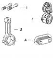
(2)使用机器拆分连杆使用TR114083,并使用TR501124与破裂的分裂连接杆。
(3)与Oil Pan code 1901,1902& 1903年,钢制油锅。
(4)使用Oil Pan code 1904& 1905年,为铝油盘。
(5)用法兰头帽螺钉替换所有R78558带帽螺钉TR85363。
(6)(m)R135439,R132324,R134213。
(7)线路连接都是线程化的。
(8)  在曲轴加工过程中必须保持适当的轴承轴颈半径,以确保正确的操作。
(9)1件组合式密封和穿套;替换TRE59810,RE538097。
(10)检查应用程序是否正确使用。
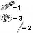
(11)与Stanadyne DE10注射泵一起使用。
(12)锥形鼻子。
(13)直鼻。
(14)线路连接是一个 软管倒钩&一个线程。
(15)线路连接是两个软管倒钩。
(16)机器分体式和断裂式分体式连杆均可用于同一台发动机,但每个连杆必须使用正确的连杆螺栓。
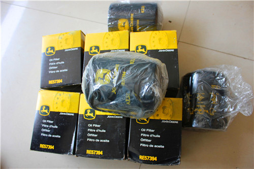
强鹿JOHN DEERE柴油机配件、发动机配件、发电机组:
RE523502、RE518520、RE68345、RE53307、RE62240、RE533095、RE502513、RE38009、R30402、RE521538、RE521540、RE62240、P524837、RE60021、RE507236、RE59588、RE549153、RE530870、SE501610、SE501609、RE70960
GRID PAGE GRID PAGE
8D13 INJECTION PUMP ACCESS COVER 3H20 INTAKE MANIFOLD (ESN XXXXXX- )
(TF150/TF220/TF250) (4404) -........ 4400 - 4410 (HF150) (1704)--..1700 - 1704
8D19 INJECTION PUMP ACCESS COVER 3I3 INTAKE MANIFOLD (ESN XXXXXX- )
(TF150/TF220/TF250) (4425) -........ 4400 - 4416 (HF150) (1706)--..1700 - 1710
8E1 INJECTION PUMP ACCESS COVER 3H21 INTAKE MANIFOLD (ESN XXXXXX- )
(TF150/TF220/TF250) (4426) -........ 4400 - 4422 (TF120) (1704)--..1700 - 1704A
8D5 INJECTION PUMP ACCESS COVER (TF151) 3H22 INTAKE MANIFOLD (ESN XXXXXX- )
(4401) (ESN -XXXXXX)-.................. 4400 - 4402 (TF150/TF220/TF250) (1704) -........ 1700 - 1704B
3I12 INLET, AIR (CODE 1713) -.................. 1700 - 1716 3I2 INTAKE MANIFOLD (ESN XXXXXX- )
9I19 INLET, WATER PUMP (DF150/TF120) (5701)................ 5700 - 5703 (TF150/TF220/TF250) (1706) -........ 1700 - 1709
9I22 INLET, WATER PUMP (DF150/TF120) (5702)................ 5700 - 5706 3I7 INTAKE MANIFOLD (ESN XXXXXX- )
9I25 INLET, WATER PUMP (DF150/TF120) (5706)................ 5700 - 5709 (TF150/TF220/TF250) (1707) -........ 1700 - 1714
9J4 INLET, WATER PUMP (DF150/TF120) (5722)................ 5700 - 5713 3H19 INTAKE MANIFOLD (ESN 079434-XXXXXX)
9J1 INLET, WATER PUMP (DF151) (5707) -.. 5700 - 5710 (TF150/TF220/TF250) (1704) -........ 1700 - 1703
9I18 INLET, WATER PUMP (HF120/HF150/HF250) 3I13 INTAKE MANIFOLD (HF150) (1716)-.. 1700 - 1717
(5701) --................ 5700 - 5702 3I4 INTAKE MANIFOLD (TF120/TF151) (1706) .................... 1700 - 1711
9I21 INLET, WATER PUMP (HF120/HF150/HF250) 3I16 INTAKE MANIFOLD (TF151) (1729)-.. 1700 - 1720
(5702) --................ 5700 - 5705 3I17 INTAKE MANIFOLD (TF250) (1752)-.. 1700 - 1721
9I24 INLET, WATER PUMP (HF120/HF150/HF250) 3I19 INTAKE MANIFOLD, NO (DF150/TF120) (1799) ............ 1700 - 1723
(5706) --................ 5700 - 5708 3I18 INTAKE MANIFOLD, NO (TF150/TF250) (1799) ............1700 - 1722
9J3 INLET, WATER PUMP (HF120/HF150/HF250) 8G1 INTAKE VALVE (DF150) (5108) -........ 5100 - 5108
(5722) --................ 5700 - 5712 8F22 INTAKE VALVE (HF120/HF150/HF250) (5107) .............. 5100 - 5104
9I17 INLET, WATER PUMP (TF150/TF220/TF250) 8F24 INTAKE VALVE (TF120/TF151) (5107)-.... 5100 - 5106
(5701) --................ 5700 - 5701 8F20 INTAKE VALVE (TF150/TF220/TF250) (5107) ................ 5100 - 5102
9I20 INLET, WATER PUMP (TF150/TF220/TF250) 3I12 INTAKE, AIR (CODE 1713)-................ 1700 - 1716
(5702) --................ 5700 - 5704 4D9 INTAKE, OIL PUMP (DF150/TF120) (1908) .................... 1900 - 1906
9I23 INLET, WATER PUMP (TF150/TF220/TF250) 4D12 INTAKE, OIL PUMP (DF150/TF120) (1909) .................... 1900 - 1909
(5706) --................ 5700 - 5707 4D6 INTAKE, OIL PUMP (DF150/TF120/TF151)
9J2 INLET, WATER PUMP (TF150/TF220/TF250) (1907) --................ 1900 - 1903
(5722) --................ 5700 - 5711 4D18 INTAKE, OIL PUMP (HF120/HF150) (1956).................... 1900 - 1915
12H23 INSTRUMENT PANEL, ENCLOSED (12V) 4D5 INTAKE, OIL PUMP (HF120/HF150/HF250)
(CODE 9701) --.... 9700 - 9762 (1907) --................ 1900 - 1902
12I1 INSTRUMENT PANEL, ENCLOSED (12V) 4D8 INTAKE, OIL PUMP (HF120/HF150/HF250)
(CODE 9701) --.... 9700 - 9764 (1908) --................ 1900 - 1905
12I3 INSTRUMENT PANEL, ENCLOSED (12V) 4D11 INTAKE, OIL PUMP (HF120/HF150/HF250)
(CODE 9701) --.... 9700 - 9766 (1909) --................ 1900 - 1908
3H23 INTAKE MANIFOLD (ESN -XXXXXX) 4D14 INTAKE, OIL PUMP (HF150/HF250) (1924).................... 1900 - 1911
(DF150) (1705)--..1700 - 1705 4D21 INTAKE, OIL PUMP (HF250) (1961)-.. 1900 - 1918
3I11 INTAKE MANIFOLD (ESN -XXXXXX) 4D19 INTAKE, OIL PUMP (TF120) (1956)-.. 1900 - 1916
(DF150) (1713)--..1700 - 1715D 4D16 INTAKE, OIL PUMP (TF120/TF151) (1944) .................... 1900 - 1913
3I14 INTAKE MANIFOLD (ESN -XXXXXX) 4D4 INTAKE, OIL PUMP (TF150/TF220/TF250)
(HF120/HF150/HF150) (1724)-........ 1700 - 1718 (1907) --................ 1900 - 1901
3I9 INTAKE MANIFOLD (ESN -XXXXXX) 4D7 INTAKE, OIL PUMP (TF150/TF220/TF250)
(HF120/HF150/HF250) (1712)-........ 1700 - 1715A (1908) --................ 1900 - 1904
3H17 INTAKE MANIFOLD (ESN -XXXXXX) 4D10 INTAKE, OIL PUMP (TF150/TF220/TF250)
(HF150) (1704)--..1700 - 1702 (1909) --................ 1900 - 1907
3I1 INTAKE MANIFOLD (ESN -XXXXXX) 4D15 INTAKE, OIL PUMP (TF150/TF220/TF250)
(HF150) (1706)--..1700 - 1708 (1944) --................ 1900 - 1912
3I6 INTAKE MANIFOLD (ESN -XXXXXX) 4D17 INTAKE, OIL PUMP (TF150/TF220/TF250)
(HF150) (1707)--..1700 - 1713 (1956) --................ 1900 - 1914
3H18 INTAKE MANIFOLD (ESN -XXXXXX) 4D13 INTAKE, OIL PUMP (TF250) (1924)-.. 1900 - 1910
(TF120) (1704)--..1700 - 1702A 4D20 INTAKE, OIL PUMP (TF250) (1961)-.. 1900 - 1917
3H16 INTAKE MANIFOLD (ESN -XXXXXX) 13F14 ISOLATOR (9901) (TF150,220,250) -.. 9900 - 9960
(TF150/TF220/TF250) (1704) -........ 1700 - 1701 13F15 ISOLATOR (9901) (TF150,220,250) -.. 9900 - 9961
3H25 INTAKE MANIFOLD (ESN -XXXXXX)
(TF150/TF220/TF250) (1706) -........ 1700 - 1707
3I5 INTAKE MANIFOLD (ESN -XXXXXX) K
(TF150/TF220/TF250) (1707) -........ 1700 - 1712
3H24 INTAKE MANIFOLD (ESN XXXXXX- ) 12E1 KIT, AIR COMPRESSOR DRIVE
(DF150) (1705)--..1700 - 1706 (ESN -XXXXXX) (DF150/TF120) (9701)...................... 9700 - 9717A
3I15 INTAKE MANIFOLD (ESN XXXXXX- ) 12E17 KIT, AIR COMPRESSOR DRIVE
(HF120/HF150/HF150) (1724)-........ 1700 - 1719 (HF150/HF250) (9701)-....................9700 - 9724
3I10 INTAKE MANIFOLD (ESN XXXXXX- ) 12E15 KIT, AIR COMPRESSOR DRIVE
(HF120/HF150/HF250) (1712)-........ 1700 - 1715B (TF150/TF220/TF250) (9701) -........ 9700 - 9722
3I8 INTAKE MANIFOLD (ESN XXXXXX- ) 12D13 KIT, AIR COMPRESSOR DRIVE (BENDIX)
(HF150 ) (1707) -- 1700 - 1715 (ESN -XXXXXX) (DF150) (9701) -.. 9700 - 9708
I-36 POWERTECH 6.8L ENGINES; TORREON(PE)(ESN 010000-), SARAN(CD)(ESN 500000-), DUBUQUE(TO)(ESN 700000-) PC2522 (06-JUN-02)
PN=44
1B20
POWERTECH 6.8L ENGINES; TORREON(PE)(ESN 010000-), SARAN(CD)(ESN 500000-), DUBUQUE(TO)(ESN 700000-)
ALPHABETICAL INDEX - CONTINUED
GRID PAGE GRID PAGE
12D11 KIT, AIR COMPRESSOR DRIVE (BENDIX) 12F15 KIT,AUXILIARY DRIVE ADAPTER (CD) & (TO)
(ESN -XXXXXX) (HF150/HF250) (9701) .................... 9700 - 9706 XXX-XXX) (TF150/TF220/TF250) (9701) .................... 9700 - 9738
12D9 KIT, AIR COMPRESSOR DRIVE (BENDIX) 12H19 KIT,AUXILIARY DRIVE ADAPTER (CD) & (TO)
(ESN -XXXXXX) (TF150/TF250) (9701) ...................... 9700 - 9704 XXXXXX-) (DF150/TF120/TF151) (9701) .................... 9700 - 9758
12D17 KIT, AIR COMPRESSOR DRIVE (BENDIX) 12H17 KIT,AUXILIARY DRIVE ADAPTER (CD) & (TO)
(ESN XXXXXX- ) (HF150/HF250) (9701) .................... 9700 - 9712 XXXXXX-) (HF120/HF150/HF250) (9701).................... 9700 - 9756
12D15 KIT, AIR COMPRESSOR DRIVE (BENDIX) 12H15 KIT,AUXILIARY DRIVE ADAPTER (CD) & (TO)
(ESN XXXXXX- ) (TF150/TF250) (9701) .................... 9700 - 9710 XXXXXX-) (TF150/TF220/TF250) (9701) .................... 9700 - 9754
12D19 KIT, AIR COMPRESSOR DRIVE (BENDIX) 12G1 KIT,AUXILIARY DRIVE ADAPTER (ESN 717569
(XXXXXX- ) (DF150) (9701) -.......... 9700 - 9713A -742889) (DF150/TF120/TF151) (9701) ...................... 9700 - 9741C
12E19 KIT, AIR COMPRESSOR DRIVE (DF150) (9701) .......... 9700 - 9725A 12F23 KIT,AUXILIARY DRIVE ADAPTER (ESN 717569
12D23 KIT, AIR COMPRESSOR DRIVE (ESN -XXXXXX) -742889) (HF120/HF150/HF250) (9701) ...................... 9700 - 9741A
(HF120/HF150/HF250) (9701)-........ 9700 - 9716 12F21 KIT,AUXILIARY DRIVE ADAPTER (ESN 717569
12D21 KIT, AIR COMPRESSOR DRIVE (ESN -XXXXXX) -742889) (TF150/TF220/TF250) (9701) ...................... 9700 - 9740
(TF150/TF220/TF250) (9701) -........ 9700 - 9714 12G13 KIT,AUXILIARY DRIVE ADAPTER (ESN 720812
12E7 KIT, AIR COMPRESSOR DRIVE (ESN XXXXXX- ) -742889) (DF150/TF120/TF151) (9701) ...................... 9700 - 9745C
(DF150/TF120) (9701) -....................9700 - 9721A 12H1 KIT,AUXILIARY DRIVE ADAPTER (ESN 720812
12E5 KIT, AIR COMPRESSOR DRIVE (ESN XXXXXX- ) -742889) (DF150/TF120/TF151) (9701) ...................... 9700 - 9749C
(HF120/HF150/HF250) (9701)-........ 9700 - 9720 12G11 KIT,AUXILIARY DRIVE ADAPTER (ESN 720812
12E3 KIT, AIR COMPRESSOR DRIVE (ESN XXXXXX- ) -742889) (HF120/HF150/HF250) (9701) ...................... 9700 - 9745A
(TF150/TF220/TF250) (9701) -........ 9700 - 9718 12G23 KIT,AUXILIARY DRIVE ADAPTER (ESN 720812
12E13 KIT, AIR COMPRESSOR DRIVE (ESN 742890- ) -742889) (HF120/HF150/HF250) (9701) ...................... 9700 - 9749A
(DF150/TF120/TF151) (9701) -........ 9700 - 9721G 12G9 KIT,AUXILIARY DRIVE ADAPTER (ESN 720812
12E11 KIT, AIR COMPRESSOR DRIVE (ESN 742890- ) -742889) (TF150/TF220/TF250) (9701) ...................... 9700 - 9744
(HF120/HF150/HF250) (9701)-........ 9700 - 9721E 12G21 KIT,AUXILIARY DRIVE ADAPTER (ESN 720812
12E9 KIT, AIR COMPRESSOR DRIVE (ESN 742890- ) -742889) (TF150/TF220/TF250) (9701) ...................... 9700 - 9748
(TF150/TF220/TF250) (9701) -........ 9700 - 9721C 12G7 KIT,AUXILIARY DRIVE ADAPTER (ESN 742890
2D17 KIT, COLD START ADVANCE (16CX) -.... 1600 - 1614 - ) (DF150/TF120/TF151) (9701) -.. 9700 - 9743C
2D22 KIT, COLD START ADVANCE (16DK) -.... 1600 - 1620 12G19 KIT,AUXILIARY DRIVE ADAPTER (ESN 742890
8F7 KIT, CYLINDER LINER O-RING - ) (DF150/TF120/TF151) (9701) -.. 9700 - 9747C
(HF120/HF150/HF250) (4810)-........ 4800 - 4805 12G5 KIT,AUXILIARY DRIVE ADAPTER (ESN 742890
8F3 KIT, CYLINDER LINER O-RING (DF150) - ) (HF120/HF150/HF250) (9701)-.. 9700 - 9743A
(4805) --................ 4800 - 4801 12G17 KIT,AUXILIARY DRIVE ADAPTER (ESN 742890
8F5 KIT, CYLINDER LINER O-RING (TF120/TF151) - ) (HF120/HF150/HF250) (9701)-.. 9700 - 9747A
(4807) --................ 4800 - 4803 12H5 KIT,AUXILIARY DRIVE ADAPTER (ESN 742890
8F4 KIT, CYLINDER LINER O-RING (TF150) - ) (HF120/HF150/HF250) (9701)-.. 9700 - 9751A
(4807) --................ 4800 - 4802 12H7 KIT,AUXILIARY DRIVE ADAPTER (ESN 742890
8F6 KIT, CYLINDER LINER O-RING (TF220/TF250) - ) (HF120/HF150/HF250) (9701)-.. 9700 - 9751C
(4810) --................ 4800 - 4804 12G3 KIT,AUXILIARY DRIVE ADAPTER (ESN 742890
13E3 KIT, ENGINE GASKET (DF150/TF120/TF151) - ) (TF150/TF220/TF250) (9701) -.. 9700 - 9742
(9901) --................ 9900 - 9922 12G15 KIT,AUXILIARY DRIVE ADAPTER (ESN 742890
13E1 KIT, ENGINE GASKET (HF120/HF150/HF250) - ) (TF150/TF220/TF250) (9701) -.. 9700 - 9746
(9901) --................ 9900 - 9920 12H3 KIT,AUXILIARY DRIVE ADAPTER (ESN 742890
13D23 KIT, ENGINE GASKET (TF150/TF220/TF250) - ) (TF150/TF220/TF250) (9701) -.. 9700 - 9750
(9901) --................ 9900 - 9918 12H9 KIT,AUXILIARY DRIVE ADAPTER (ESN 742890
13E3 KIT, ENGINE OVERHAUL (DF150/TF120/TF151) - ) (TF150/TF220/TF250) (9701) -.. 9700 - 9752
(9901) --................ 9900 - 9922 12H11 KIT,AUXILIARY DRIVE ADAPTER (ESN 742890
13E1 KIT, ENGINE OVERHAUL (HF120/HF150/HF250) - ) (TF150/TF220/TF250) (9701) -.. 9700 - 9753A
(9901) --................ 9900 - 9920 12H13 KIT,AUXILIARY DRIVE ADAPTER (ESN 742890
13D23 KIT, ENGINE OVERHAUL (TF150/TF220/TF250) - ) (TF150/TF220/TF250) (9701) -.. 9700 - 9753C
(9901) --................ 9900 - 9918
13D17 KIT, OVERHAUL (DF150/TF120/TF151) (9901).............. 9900 - 9912
13D15 KIT, OVERHAUL (HF120/HF150/HF250) (9901) ............ 9900 - 9910 L
13D13 KIT, OVERHAUL (TF150/TF220/TF250) (9901) .............. 9900 - 9908
13F16 KIT, TIMING GEAR COVER SERVICE (9901)................ 9900 - 9962 2G1 LEVERS, FUEL INJECTION PUMP (16UG).................... 1600 - 1666
13F17 KIT, TIMING GEAR COVER SERVICE (9901)................ 9900 - 9963 3E13 LEVERS, FUEL INJECTION PUMP (1622) ....................
1600A - 1632
13F18 KIT, TIMING GEAR COVER SERVICE (9901)................ 9900 - 9964 3E21 LEVERS, FUEL INJECTION PUMP (1623) ....................
1600A - 1640
12F13 KIT,AUXILIARY DRIVE ADAPTER (CD) & (TO) 3F5 LEVERS, FUEL INJECTION PUMP (1668) ....................
1600A - 1648
XXX-XXX) (DF150/TF120/TF151) (9701) .................... 9700 - 9737C 9D23 LINE, AUX DR ADAPTER (ESN (CD) & (TO)
12F19 KIT,AUXILIARY DRIVE ADAPTER (CD) & (TO) XXX-XXX) (DF150/TF120) (5201)-.. 5200 - 5213A
XXX-XXX) (DF150/TF120/TF151) (9701) .................... 9700 - 9739C 9D21 LINE, AUX DR ADAPTER (ESN (CD) & (TO)
12F11 KIT,AUXILIARY DRIVE ADAPTER (CD) & (TO) XXX-XXX) (HF120/HF150/HF250) (5201).................... 5200 - 5212
XXX-XXX) (HF120/HF150/HF250) (9701).................... 9700 - 9737A 9D19 LINE, AUX DR ADAPTER (ESN (CD) & (TO)
12F17 KIT,AUXILIARY DRIVE ADAPTER (CD) & (TO) XXX-XXX) (TF150/TF220/TF250) (5201) .................... 5200 - 5210
XXX-XXX) (HF120/HF150/HF250) (9701).................... 9700 - 9739A 9F7 LINE, AUX DR ADAOPTER (5203)-.... 5200 - 5234
12F9 KIT,AUXILIARY DRIVE ADAPTER (CD) & (TO) 9F1 LINE, AUX DR ADAPTER
XXX-XXX) (TF150/TF220/TF250) (9701) .................... 9700 - 9736 (ESN -XXXXXX) (5203) -........ 5200 - 5230
POWERTECH 6.8L ENGINES; TORREON(PE)(ESN 010000-), SARAN(CD)(ESN 500000-), DUBUQUE(TO)(ESN 700000-) PC2522 (06-JUN-02) I-37
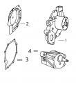
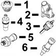
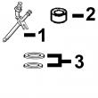
PN=45specification acces***y gear-to-shaft— torque . 55 n?m (41 lb-ft) auxiliary equipment-to-engine (cap screw/nut)—torque 50 n?m (35 lb-ft) ctm125 (14jun01) 20-20 powertech 2.9 l diesel engines 061401 pn=136 group 25 lubrication system 25 1 cd,ctm125,152 –19–01dec97–1/1 oil cooler identification cd30405 –un–10may95 the 6-plates oil cooler (a) is clamped between oil filter and cylinder block/adaptation housing. cd,ctm125,137 –19–01dec97–1/1 remove oil cooler cd30271 –un–06mar95 cd30616 –un–24jun98 cd30615 –un–04may98 a—inlet line from water pump b—outlet line to water pump c—nipple d—holding screw 1. disconnect inlet line (a)&outlet line (b) at oil cooler. 2. remove nipple (c)/holding screw (d)&lift out oil cooler. 3. discard packing. ctm125 (14jun01) 25-1 powertech 2.9 l diesel engines 061401 pn=137 lubrication system 25 2 cd,ctm125,138 –19–01dec97–1/1 replace oil cooler nipple cd30275 –un–06mar95 1. remove oil cooler nipple (a). 2. press in new nipple so that threaded end faces outward (farthest point from cylinder block). cd,ctm125,139 –19–24jan01–1/1 install oil cooler on standard engine cd30617 –un–04may98 1. install new packing between oil cooler&cylinder block. 2. attach oil cooler with nipple (a). tighten to specification. specification oil cooler nipple—torque . 35 n?m (25 lb-ft) 3. connect coolant lines to oil cooler. 4. install oil filter. ctm125 (14jun01) 25-2 powertech 2.9 l diesel engines 061401 pn=138 lubrication system 25 3 cd,ctm125,140 –19–24jan01–1/1 replace oil cooler/filter bracket on engine with auxiliary drive cd30618 –un–16jun98 a—oil cooler/filter bracket d—fitting f—oil cooler h—o-ring b—packing e—packing g—nipple j—oil filter c—holding screw 1. remove oil cooler/filter bracket (a). 2. clean&check parts. 3. install bracket (a) with a new packing (b). tighten holding screw (c) to specification. 4. install fitting (d) onto bracket. tighten to specification. 5. install a new packing (e) between oil cooler (f) and bracket. 6. attach oil cooler with nipple (g). tighten to specification. 7. connect coolant lines to oil cooler. 8. install oil filter (j). standard oil cooler/oil filter bracket on engine with camshaft-gear-driven auxiliary drive—specification oil cooler/filter bracket holding screw (c)—torque . 35 n?m (25 lb-ft) oil filter fitting (d)—torque . 45 n?m (33 lb-ft) oil cooler nipple (g)—torque 35 n?m (25 lb-ft) ctm125 (14jun01) 25-3 powertech 2.9 l diesel engines 061401 pn=139 lubrication system 25 4 cd,ctm125,141 –19–24jan01–1/1 replace oil filter adapter on engine with remote oil filter cd30619 –un–24jun98 a—holding screw e—oil cooler h—o-ring l—oil hose b—o-ring f—packing j—o-ring m—fitting c—cover g—oil filter adapter k—fitting n—oil filter d—o-ring 1. remove special screw (a) holding both the oil cooler (e)&the oil filter adapter (g). 2. disconnect oil hoses (l) from adapter. 3. clean&check parts. 4. install adapter with a new o-ring (h), then attach oil cooler with packing (, f), cover (c)&o-rings (d) and (b). tighten holding screw (a) to specification specification oil filter adapter/oil cooler holding screw (remote oil filter)—torque . 35 n?m (25 lb-ft) 5. reconnect oil hoses to adapter&coolant lines to oil cooler. cd,ctm125,142 –19–24jan01–1/1 remove oil pressure regulating valve cd30620 –un–04may98 remove oil pressure regulating valve plug. check spring load&valve cone for excessive wear&damaged sealing face. specification oil pressure regulating valve spring—load at a length of 42.5 mm (1.68 in.) . 60 to 75 n (13.5 to 16.5 lb.) ctm125 (14jun01) 25-4 powertech 2.9 l diesel engines 061401 pn=140 lubrication system 25 5 cd,ctm125,143 –19–24jan01–1/1 replace oil pressure regulating valve seat cd7175a –un–07mar95 1. remove valve seat bushing, using a suitable puller. 2. drive in new bushing, using special tools jd-248a and jdg536/otc813 until driver contacts cylinder block. important: do not damage the slightly protruding edge of the bushing as it is a sealing face. cd,ctm125,144 –19–24jan01–1/1 install oil pressure regulating valve cd30413 –un–10may95 note: one/several shims (a) may be used to adjust the oil pressure. 1. install valve, spring, shims, washer&plug in timing gear cover. 2. tighten plug as specified. specification oil pressure regulating valve plug—torque . 95 n?m (70 lb-ft) ctm125 (14jun01) 25-5 powertech 2.9 l diesel engines 061401 pn=141 lubrication system 25 6 cd,ctm125,145 –19–24jan01–1/1 replace oil dipstick guide z20746 –un–08mar95 1. loosen lock nut&unscrew dipstick guide. 2. apply sealing compound on thread of new guide. 3. install new dipstick guide&adjust height (x) in accordance with specifications. cd,ctm125,146 –19–24jan01–1/1 replace oil by-pass valve cd30622 –un–04may98 1. remove timing gear cover&front plate. 2. remove oil by-pass valve&spring (a). inspect valve and spring for damage. 3. check spring load&compare with specification. specification oil by-pass valve spring—load at a length of 29 mm (1.14 in.) 79 to 96.5 n (18 to 22 lb.) 4. install oil by-pass valve&spring. 5. install front plate&timing gear cover. ctm125 (14jun01) 25-6 powertech 2.9 l diesel engines 061401 pn=142 lubrication system 25 7 cd,ctm125,147 –19–24jan01–1/1 replace oil pump strainer cd30623 –un–04may98 1. remove oil pan. 2. loosen the two lower cap screws (a)&remove oil strainer. 3. install new strainer with new o-ring&tighten cap screws to specification. specification oil pump strainer screws— torque . 50 n?m (35 lb-ft) 4. reinstall oil pan. cd,ctm125,148 –19–24jan01–1/1 remove oil pump cd7176 –un–07mar95 a—oil pump drive gear nut b—oil pump drive gear c—screw 1. remove oil pan&timing gear cover. 2. remove nut (a) from pump shaft. 3. pull gear (b) from conical shaft of pump, using a suitable puller. 4. remove the 3 cap screws (c) attaching pump housing to front plate. cd,3274,g25,26 –19–24jan01–1/1 oil pump gear axial clearance cd7177 –un–07mar95 oil pump gear axial clearance—specification gear—thickness 41.15 to 41.20 mm (1.62 to 1.622 in.) axial clearance 0.05 to 0.17 mm (0.002 to 0.007 in.) . wear tolerance . 0.22 mm (0.0085 in.) ctm125 (14jun01) 25-7 powertech 2.9 l diesel engines 061401 pn=143 lubrication system 25 8 cd,3274,g25,27 –19–24jan01–1/1 oil pump gear radial clearance cd7178 –un–07mar95 specification oil pump—radial clearance between gear&pump housing 0.10 to 0.16 mm (0.004 to 0.006 in.) wear tolerance . 0.20 mm (0.008 in.) cd,ctm125,153 –19–24jan01–1/1 oil pump specifications t81953 –un–09nov88 t81781 –un–09nov88 oil pump—specification drive shaft bore—diameter 16.05 to 16.08 mm (0.632 to 0.633 in.) . wear tolerance 0.08 mm (0.003 in.) drive shaft—diameter 16.02 to 16.03 mm (0.630 to 0.631in.) . wear tolerance 0.025 mm (0.001 in.) idler shaft—diameter 12.32 to 12.34 mm (0.485 to 0.486 in.) . wear tolerance 0.013 mm (0.0005 in.) ctm125 (14jun01) 25-8 powertech 2.9 l diesel engines 061401 pn=144 lubrication system 25 9 cd,ctm125,150 –19–24jan01–1/3 oil pump installation cd30416 –un–10may95 1—cylinder block seal 5—spring pin 9—outlet tube 12—cap screws (3/4 used) 2—o-ring (outlet tube) 6—gears 10—strainer 13—drive gear 3—o-ring (oil strainer tube) 7—shaft 11—cover 14—nut 4—drive shaft 8—housing cd,ctm125,150 –19–24jan01–2/3 cd30624 –un–04may98 cd30625 –un–16jun98 1. install new seal (a) in cylinder block. 2. using jdg127 o-ring seal tool set, install o-rings in pump cover (for outlet tube)&on oil strainer tube. 3. install drive shaft with gear&idler gear in pump housing. both gears must turn freely. 4. install outlet tube, strainer&pump cover. note: service oil pump kit has two outlet tube. install tube without paint mark (b). ctm125 (14jun01) 25-9 powertech 2.9 l diesel engines 061401 pn=145 continued on next page lubrication system 25 10 cd,ctm125,150 –19–24jan01–3/3 cd7176 –un–07mar95 t81782 –un–09nov88 5. attach oil pump assembly to front plate, tightening cap screws (c) to specification. specification oil pump-to-front plate, screws—torque 50 n?m (35 lb-ft) 6. rotate pump shaft, again making sure that pump gears turn freely. 7. install pump drive gear (b)&a new nut (a). tighten to specification. specification oil pump drive gear nut— torque . 75 n?m (55 lb-ft) 8. secure the nut by applying three center punch marks. note: engine may be equipped with a self-lock nut. when reassebling such engine, use the standard nut&tighten as indicated above. ctm125 (14jun01) 25-10 powertech 2.9 l diesel engines 061401 pn=146 lubrication system 25 11 cd,ctm125,151 –19–24jan01–1/1 install oil pan cd30627 –un–04may98 cd30626 –un–16jun98 1. place loctite? 515 sealant (or an equivalent sealant) on oil pan rail where flywheel housing, front plate&timing gear cover are attached to the cylinder block. note: a tube of loctite? 515 sealant is provided with overhaul gasket set. this tube is also available under part number dd15664. 2. select&install the correct gasket for the oil pan being used. 3. install oil pan&tighten cap screws as follows: specification oil pan (all types)-to-timing gear cover—torque . 50 n?m (35 lb-ft) sheet metal oil pan-to-block and flywheel housing—torque . 50 n?m (35 lb-ft) aluminium oil pan-to-block and flywheel housing—torque . 50 n?m (35 lb-ft) cast iron pan-to-block and flywheel housing: sae 5 screws (3 dashes)—torque . 50 n?m (35 lb-ft) cast iron pan-to-block and flywheel housing: sae 8 screws (6 dashes)—torque . 70 n?m (50 lb-ft) 4. install a new seal onto cylindrical drain plug. tighten as follows: oil pan drain plug —specification cylindrical plug with copper seal—torque . 70 n?m (50 lb-ft) cylindrical plug with o-ring seal— torque . 50 n?m (35 lb-ft) conical plug—torque 55 n?m (40 lb-ft) loctite is a trademark of loctite corp. ctm125 (14jun01) 25-11 powertech 2.9 l diesel engines 061401 pn=147 lubrication system 25 12 ctm125 (14jun01) 25-12 powertech 2.9 l diesel engines 061401 pn=148 group 30 cooling system 30 1 cd,ctm125,156 –19–01dec97–1/1 water pump — exploded view cd30628 –un–17jun98 a—housing c—seal e—gasket g—hub (or pulley) b—bearing shaft d—impeller f—rear cover cd,ctm125,157 –19–01dec97–1/1 remove water pump cd30629 –un–04may98 1. remove fan&sheet metal pulley when equipped. 2. disconnect water pump hoses (a). 3. remove attaching screws (b)&nut (c) then lift out water pump. ctm125 (14jun01) 30-1 powertech 2.9 l diesel engines 061401 pn=149 cooling system 30 2 cd,ctm125,158 –19–25jan01–1/1 disassemble water pump cd30632 –un–16jun98 cd30631 –un–04may98 cd30630 –un–16jun98 pre-assembled water pump a—rear cover b—pulley c—bearing shaft d—impeller e—housing f—seal g—weep hole h—pre-assembled water pump note: when water pump operation is abnormal/when coolant drains from hole (g), disassemble water pump as follows. 1. remove rear cover (a)&discard gasket. 2. using a suitable puller, remove pulley (b)/hub from bearing shaft (c). 3. support pulley end of housing, then using a 13 mm (0.5 in.) driver, simultaneously remove impeller (d) from bearing shaft&bearing shaft from pump housing (e). discard bearing&impeller. 4. using a suitable driver, remove seal (f) from pump housing&discard. 5. inspect water pump housing, cover&pulley for wear, debris, cracks/other damage. replace as necessary. note: complete/pre-assembled (h) water pumps are available for service as well as a seal kit including bearing shaft (c), impeller (d), seal (f) and gasket set. ctm125 (14jun01) 30-2 powertech 2.9 l diesel engines 061401 pn=150 cooling system 30 3 cd,ctm125,162 –19–25jan01–1/4 assemble water pump cd30633 –un–04may98 1. use jd-262a (jd262a) (a) to install bearing shaft. 2. press bearing shaft into housing until bearing face is flush with housing. a flat washer (b) can be used to stop the driver&ensure a proper installation. cd,ctm125,162 –19–25jan01–2/4 cd30634 –un–19may98 cd30635 –un–19may98 3. support water pump on shaft end. using the installation tool (a) included in the seal kit, install water pump seal (b) over shaft until seal bottoms on shoulder (c) of housing. note: install seal dry. installation tool (a) must be used as it exerts the proper pressure on seal and therefore avoids risk to damage the seal faces. continued on next page ctm125 (14jun01) 30-3 powertech 2.9 l diesel engines 061401 pn=151 cooling system 30 4 cd,ctm125,162 –19–25jan01–3/4 cd30636 –un–04may98 cd30637 –un–04may98 4. place pump housing under a press&support on pulley end of shaft. 5. using special tool jd-262a (jd262a), press impeller onto pump shaft until flush with pump housing face within clearance specification. specification impeller-to-water pump housing—clearance . 0 to -0.25 mm (0 to -0.01 in.) cd,ctm125,162 –19–25jan01–4/4 cd30638 –un–04may98 cd30652 –un–16jun98 6. place pump housing under a press&support on impeller end of shaft. 7. install pulley/hub to the specified dimension “a” (see specifications). ctm125 (14jun01) 30-4 powertech 2.9 l diesel engines 061401 pn=152 cooling system 30 5 cd,ctm125,163 –19–25jan01–1/1 install water pump cd30629 –un–04may98 a—coolant hose b—cap screw c—nut 1. attach pump cover to pump housing using a new gasket&tighten cap screws to specification. 2. install water pump, placing a new gasket between the pump cover&cylinder block. tighten cap screws (b) and nut (c) to specification. specification water pump housing-to-cover, cap screws—torque 45 n?m (33 lb-ft) water pump-to-engine, cap screws—torque 50 n?m (35 lb-ft) water pump-to-engine, nut— torque . 40 n?m (30 lb-ft) 3. connect coolant hoses (a). ctm125 (14jun01) 30-5 powertech 2.9 l diesel engines 061401 pn=153 cooling system 30 6 cd,ctm125,205 –19–25jan01–1/1 inspect thermostat cd30640 –un–16jun98 cd30641 –un–04may98 a—thermostat cover c—cylinder head orifice e—gasket g—jiggle pin b—by-pass tube d—guide stud f—thermostat 1. visually inspect area around thermostat cover (a) for leaks. partially drain coolant from system. 2. remove by-pass tube (b) from thermostat cover. 3. remove thermostat cover from cylinder head (c). 4. test thermostat (f) in hot water for correct opening and closing temperature (see engine system - diagnosis&test). replace if defective. 5. remove gasket material from gasket surfaces. 6. using guide studs (d), install a new gasket (e) onto cylinder head. 7. place thermostat (f) in cover with jiggle pin (g) on top for a proper deaerat, ion. 8. using a screwdriver to hold thermostat in place, install cover. tighten cap screws to specification. specification thermostat cover cap screws— torque . 50 n?m (35 lb-ft) 9. install by-pass tube into thermostat cover. tighten clamp. 10. fill cooling system&check for leaks. cd03523,0000100 –19–26jan01–1/1 cold start advance switch cd30682 –un–16jun98 engine may have an injection pump with a cold start advance system to allow easy start-up when engine is cold. the temperature signal is given by a switch (a) located in thermostat cover. tighten this switch as specified. specification cold start advance switch— torque 5 n?m (3.5 lb-ft) ctm125 (14jun01) 30-6 powertech 2.9 l diesel engines 061401 pn=154 cooling system 30 7 cd,ctm125,165 –19–01dec97–1/1 cooling system deaeration cd30642 –un–16jun98 cd30643 –un–04may98 deaeration is normally accomplished by the jiggle pin (a) in thermostat flange area. however a pocket of air can stay on the top rear of engine. when refilling cooling system, loosen coolant temperature sen*** or plug at the rear of cylinder head (b) to allow air to escape. ctm125 (14jun01) 30-7 powertech 2.9 l diesel engines 061401 pn=155 cooling system 30 8 cd,ctm125,166 –19–26jan01–1/2 check fan/alternator belt tension cd30644 –un–04may98 cd30645 –un–04may98 a—jdg529 tension gauge b—tension tester c—straightedge 1. check belt tension using one of following methods: note: on engine with dual belts, check tension of front belt only. a. use of jdg529 tension gauge (a) fan/alternator belt—specification single belt (new belt)—tension . 578—622 n (130—140 lb-force) single belt (used belt1 )—tension . 378—423 n (85—94 lb-force) dual belt (new belt)—tension . 423—467 n (95—104 lb-force) dual belt (used belt1 )—tension 378—423 n (85—94 lb-force) b. use of tension tester (b)&straightedge (c) specification fan/alternator belt—tension 19 mm (0.75 in.) deflection with an 90 n (20 lb-force) halfway between pulleys . 1belts are considered used after 10 minutes of operation. cd,ctm125,166 –19–26jan01–2/2 cd30646 –un–04may98 2. if adjustment is necessary, loosen alternator nuts (d) and (e). pull alternator frame outward until belt is correctly tensioned. important: do not pry against the alternator rear frame. do not tighten/loosen belts while they are hot. 3. tighten alternator bracket nuts firmly. 4. run engine for 10 minutes then recheck belt tension. ctm125 (14jun01) 30-8 powertech 2.9 l diesel engines 061401 pn=156 cooling system 30 9 cd,ctm125,167 –19–26jan01–1/1 install fan cd30647 –un–16jun98 cd30648 –un–16jun98 suction fan (top view) cd30649 –un–16jun98 blower fan (top view) a—fan b—spacer c—cap screw d—lock washer e—flat washer 1. inspect fan blades for bent/damaged condition. bent blades reduce cooling system efficiency&throw the fan out of balance. replace if necessary. note: depending on application, engine may be equipped with either suction-type/blower-type fan. take care not to install the fan wrongly. refer to illustrations to identify the fan type&the corresponding installation. 2. on water pump with hub, install first the sheet metal pulley. 3. install fan (a) with spacer (b) when required. 4. install cap screws (c) with new lock washers (d) and, when required, flat washers (e). tighten as specified. specification fan-to-pulley, 5/16 in. cap screws—torque . 30 n?m (22 lb-ft) fan-to-pulley, 3/8 in. cap screws—torque . 50 n?m (35 lb-ft) ctm125 (14jun01) 30-9 powertech 2.9 l diesel engines 061401 pn=157 cooling system 30 10 cd,ctm125,169 –19–26jan01–1/3 coolant heater cd30723 –un–23feb99 a—coolant heater d—electrical cord g—hexagonal cap j—engine coolant temperature b—heater element: re64803 e—clamp h—engine coolant sen*** in thermostat (240 v, 1000 w) f—coolant temperature temperature sen*** in cyl. housing c—adapter sen*** for heater block regulation the coolant heater is installed at the rear of cylinder block coolant gallery. this coolant heater heats engine coolant resulting in a better starting performance. furthermore, the engine will reach its operating temperature more quickly. the coolant heater keeps the temperature between 26°c (80°f)&37°c (100°f). a temperature sen*** (f), located at the rear of the cylinder head, allows to leave the coolant heater on power supply indefinitely. continued on next page ctm125 (14jun01) 30-10 powertech 2.9 l diesel engines 061401 pn=158 cooling system 30 11 cd,ctm125,169 –19–26jan01–2/3 cd30651 –un–16jun98 note: due to the location of the coolant temperature sen*** for heater regulation at the rear of the cylinder head, the engine coolant temperature sen*** is located either in cyl. block (h)/in thermostat housing (j). precaution for removal important: heater element (a) is bent to avoid interference with cylinder block walls. for removal, do not turn neither the heater element nor the conical adapter (b). failure to this will irremediably damage the heater element. 1. apply a pulling motion between heater element and adapter to release the conical assembly. 2. pull out heater element from cylinder block. it is not necessary to remove the conical adapter. cd,ctm125,169 –19–26jan01–3/3 cd563p3 –un–31oct96 installation 1. apply loctite? 609 (jd part number: ty15969) retaining compound/equivalent to heater element tapered surface&to conical adapter. 2. install heater element in cylinder block. be sure that heater element do not touch internal walls of the block. 3. when heater element is properly positioned, tap into place with a rubber mallet. 4. connect electrical cord to heater element&fix it with the clamp using a pliers. loctite is a trademark of loctite corp. ctm125 (14jun01) 30-11 powertech 2.9 l diesel engines 061401 pn=159 cooling system 30 12 cd03523,0000105 –19–26jan01–1/1 radiator exploded view (cd3209df128) cd30806 –un–13apr01 1—radiator bracket 8—spacer 15—lock washer 22—main fan guard 2—cap screw (5/8”x1-1/2”) 9—cap screw (m8x18) 16—nut 23—secondary fan guard 3—lock washer 10—flat washer 17—drain tap 24—reinforcement 4—cap screw (9/16”x2-1/4”) 11—lock washer 18—copper seal 25—rubber mount 5—lock washer 12—nut 19—upper hose 26—nut 6—nut 13—radiator 20—lower hose 27—cap screw (1/2”x1”) 7—rubber mount 14—cap screw (m10x60) 21—clamp 28—cap screw (m8x12) ctm125 (14jun01) 30-12 powertech 2.9 l diesel engines 061401 pn=160 group 35 air intake&exhaust system 35 1 cd,ctm125,172 –19–29jan01–1/1 check air inlet pipe cd30653 –un–04may98 1. loosen hose clamps (a) holding air inlet hose. 2. remove air inlet pipe (b). 3. inspect inlet pipe for serviceability&repair or replace, if it is cracked/otherwise damaged. 4. inspect machined mating surfaces of cylinder head and inlet pipe. clean as required, using a scraper and/or wire brush&compressed air. 5. to install inlet pipe, reverse removal procedure and use new gaskets. 6. make sure that air inlet hose is in good condition. tighten hose clamps securely. 7. tighten air inlet pipe attaching cap screws (c) to specification. specification intake manifold-to-cylinder head, cap screws—torque 50 n?m (35 lb-ft) ctm125 (14jun01) 35-1 powertech 2.9 l diesel engines 061401 pn=161 air intake&exhaust system 35 2 cd,ctm125,173 –19–01dec97–1/1 exhaust manifold inspection cd30654 –un–04may98 1. on engines with turbocharger, remove turbocharger. 2. remove cap screws (a)&lift off exhaust manifold. 3. inspect exhaust manifold for serviceability&replace if it is cracked/otherwise damaged. note: exhaust manifold may have been factory-installed using liquid sealant. when re-installing manifold, use standard gaskets. gaskets with one steel-backed side must be installed with the non-steel backed side toward cylinder head. 4. to install exhaust manifold, reverse removal procedure and use new gaskets. 5. tighten exhaust manifold attaching cap screws to specification. specification exhaust manifold-to-cylinder head, cap screws—torque . 50 n?m (35 lb-ft) ctm125 (14jun01) 35-2 powertech 2.9 l diesel engines 061401 pn=162 air intake&exhaust system 35 3 cd,ctm125,174 –19–31jan01–1/1 remove turbocharger cd30655 –un–20may98 high mount cd30656 –un–20may98 side mount a—clamp b—oil inlet oil c—oil return tube d—cap screw 1. thoroughly clean exterior of turbocharger and surrounding area. 2. loosen clamp (a) holding the air inlet pipe. 3. disconnect oil inlet line (b)&return tube (c) and plug turbocharger orifices immediately to prevent entry of dirt. 4. remove air cleaner hose. 5. remove muffler connection. 6. unscrew the four cap screws (d)&remove turbocharger assembly from exhaust manifold. ctm125 (14jun01) 35-3 powertech 2.9 l diesel engines 061401 pn=163 air intake&exhaust system 35 4 cd,ctm125,175 –19–31jan01–1/1 turbocharger cut-away view (schwitzer) cd30657 –un–16jun98 1—compres*** cover 7—circlip 13—thrust sleeve 18—piston ring 2—compres*** locknut 8—o-ring 14—central housing 19—turbine housing 3—compres*** wheel 9—o-ring 15—circlip 20—shaft & wheel assy. 4—flinger 10—circlip 16—turbine backplate 21—clamp ring 5—piston ring 11—oil deflector 17—journal bearing 22—cap screw (qty: 3) 6—insert 12—thrust bearing ctm125 (14jun01) 35-4 powertech 2.9 l diesel engines 061401 pn=164 air intake&exhaust system 35 5 cd,ctm125,176 –19–31jan01–1/2 check radial clearance cd7195 –un–23may95 garrett turbocharger 1. using an adapter with indicator extension rod, fasten a dial indicator to the turbocharger&place indicator rod against compres*** shaft through lube hole. 2. move shaft alternately toward&away from indicator. 3. applying equal pressure to both ends of shaft, compare the radial bearing end play with specification. garrett turbocharger—specification ta25 model—radial clearance 0.06—0.13 mm (0.0024—0.005 in.) if radial clearance is not within specifications, replace turbocharger. cd,ctm125,176 –19–31jan01–2/2 cd30658 –un–04may98 schwitzer turbocharger 1. remove compres*** cover. 2. install a dial indicator against shaft end. 3. move shaft alternately toward&away from indicator. range of travel should not exceed specification. schwitzer turbocharger—specification s1b model—radial clearance . 0.51 mm (0.20 in.) maxi if radial clearance is exceeds specifications, replace turbocharger. ctm125 (14jun01) 35-5 powertech 2.9 l diesel engines 061401 pn=165 air intake&exhaust system 35 6 cd,ctm125,177 –19–31jan01–1/1 check axial clearance cd30659 –un–04may98 1. using a dial indicator with indicator rod against shaft, measure axial end play. 2. move shaft axially back&forth by hand. compare reading with specification. garrett turbocharger—specification ta25 model—axial clearance 0.025—0.09 mm (0.001—0.0035 in.) . schwitzer turbocharger—specification s1b model—axial clearance 0.14 mm (0.0055 in.) maxi if axial clearance is not within specifications, replace turbocharger. cd,ctm125,178 –19–01dec97–1/1 repair turbocharger due to special tooling&highly specialized personnel required, turbochargers can be serviced only by an authorized workshop. only complete turbochargers are available through service parts channel. individual components for repair are not available. cd,ctm125,179 –19–01dec97–1/1 prelube turbocharger cd30660 –un–04may98 important: do not spin the rotor assembly with compressed air. rotor may seize due to high speed reached. fill oil inlet/drain port with clean engine oil&spin rotating assembly (by hand) to properly lubricate bearings. ctm125 (14jun01) 35-6 powertech 2.9 l diesel engines 061401 pn=166 air intake&exhaust system 35 7 cd,ctm125,180 –19–31jan01–1/2 install turbocharger cd30661 –un–17jun98 install turbocharger a—exhaust manifold d—cap screw g—oil inlet line j—circlip b—gasket e—turbine housing h—oil return tube k—compres*** cover c—cap screw f—center housing 1. install turbocharger on exhaust manifold (a) with a new gasket (b). tighten cap screws (c) to specification. note: turbocharger for service are designed for a specific application. in case where engine connections are not in line with turbocharger connections, follow the procedure described in step 2. otherwise go directly to step 3. 2. procedure to re-orient turbocharger housings: a. loosen cap screws (d) of turbine housing (e). b. rotate center housing (f) until oil inlet is in line with oil supply tube (g)&oil outlet is in line with oil return tube (h). c. tighten turbine housing cap screws (d) to specification. d. compress circlip (j) securing compres*** cover (k), then rotate until in line with air inlet pipe. release circlip. 3. if not done previously, prelube turbocharger then reconnect the oil supply line (g). tighten to specification. ctm125 (14jun01) 35-7 powertech 2.9 l diesel engines 061401 pn=167 continued on next page air intake&exhaust system 35 8 cd,ctm125,180 –19–31jan01–2/2 cd551p7 –un–08nov96 5000/5010 tractors cd551p8 –un–08nov96 other applications a—re65182 oil return tube c—r129647 hose e—ar21837 clamp g—previous turbocharger oil (5000/5010 tractors) d—r82859 fitting f—at18904 clamp return hole location b—re65184 oil return tube (other applications) 4. reconnect the oil return tube (a)/(b). tighten to specification. note: when cylinder block is replaced, turbocharger oil return line may need to be connected differently from original installation. depending on application, order the parts as indicted in legend. 5. reconnect exhaust system&air hoses. important: be sure that the air hose connections are tight to prevent entry of dirt into engine. garrett turbocharger—specification turbocharger-to-exhaust manifold—torque . 30 n?m (20 lb-ft) center housing-to-turbine housing—torque 25 n?m (18 lb-ft) oil inlet line-to-turbocharger— torque . 25 n?m (18 lb-ft) oil return line-to-turbocharger—torque 80 n?m (60 lb-ft) schwitzer turbocharger—specification turbocharger-to-exhaust manifold—torque . 30 n?m (20 lb-ft) center housing-to-turbine housing—torque 25 n?m (18 lb-ft) oil inlet line-to-turbocharger— torque . 25 n?m (18 lb-ft) oil return line-to-turbocharger—torque 80 n?m (60 lb-ft) ctm125 (14jun01) 35-8 powertech 2.9 l diesel engines 061401 pn=168 air intake&exhaust system 35 9 cd,ctm125,181 –19–01dec97–1/1 turbocharger break-in important: a new/repaired turbocharger does not have adequate oil supply. perform the following steps to prevent damage to turbocharger. 1. to avoid engine starts, proceed as follows according to application: ? either push the throttle lever to “stop” position, ?/hold engine shut-off knob out, ?/disconnect electrical cable from fuel injection pump. 2. crank engine by means of starting motor until needle of engine oil pressure gauge is in green zone/until indicator light (engine oil pressure) goes out. cd,ctm125,182 –19–01dec97–1/1 recommendations for turbocharger use in most cases, turbocharger damage is caused by improper start-up&shutdown procedure. always idle the engine for at least 30 seconds (no load) after start-up&before shutdown. important: should the engine stall when operating under load, immediately restart the engine to prevent overheating of turbocharger parts. ctm125 (14jun01) 35-9 powertech 2.9 l diesel engines 061401 pn=169 air intake&exhaust system 35 10 cd03523,0000107 –19–31jan01–1/2 air filter exploded view cd30807 –un–17apr01 light duty configuration 1—air filter 3—hose 4—air restriction indicator 5—clamp 2—clamp note: applies only to air filters installed by john deere. continued on next page ctm125 (14jun01) 35-10 powertech 2.9 l diesel engines 061401 pn=170 air intake&exhaust system 35 11 cd03523,0000107 –19–31jan01–2/2 cd557d2 –un–17apr01 medium duty configuration a—clamp g—air cleaner assembly m—cap screw s—lifting strap b—rain cap h—filter element n—washer t—clamp c—clamp j—lock washer p—washer u—sleeve d—hose k—nut q—clamp v—spring e—bracket l—cap screw r—cap screw w—air restriction indicator f—lock washer ctm125 (14jun01) 35-11 powertech 2.9 l diesel engines 061401 pn=171 air intake&exhaust system 35 12 ctm125 (14jun01) 35-12 powertech 2.9 l diesel engines 061401 pn=172 group 40 fuel system 40 1 cd,ctm125,187 –19–01dec97–1/1 replace fuel filter element cd30667 –un–17jun98 cd30665 –un–16jun98 cd30664 –un–04may98 a—retaining ring b—filter element c—sediment glass bowl d—bleed screw e—drain screw note: for proper filter servicing&replacement, see operator’s manual. 1. if equipped, rotate the fuel inlet valve to the closed position. 2. unfasten filter retaining ring (a)&remove filter element (b). note: for a cleaner service, obturate the previous element with the plug provided with the new element. 3. if equipped, remove sediment glass bowl (c) from filter element&reinstall it onto the new element. 4. install dust seal (f) as shown. 5. position new element in proper location then tighten about 1/3 turn until retaining ring fits into the detent. do not overtighten. 6. bleed fuel system. ctm125 (14jun01) 40-1 powertech 2.9 l diesel engines 061401 pn=173 fuel system 40 2 cd,ctm125,188 –19–05feb01–1/1 replace fuel filter assembly cd30666 –un–16jun98 a—fuel line c—plug e—adaptor f—fitting b—fuel filter head-to-engine, d—fuel inlet valve cap screw 1. disconnect fuel lines (a). 2. unscrew cap screws (b)&remove fuel filter assembly. 3. replace parts as necessary, then tighten cap screws (b) to specification. 4. install plugs (c) on filter head&tighten to specification. 5. if equipped, install fuel inlet valve (d) on adaptor (e), then install the assembly on filter head. 6. install fittings (f) on filter head. 7. install fuel lines then tighten to specification. round fuel filter assembly—specification fuel filter head-to-engine bolts—torque . 50 n?m (37 lb-ft) plug-to-fuel filter head— torque 5 n?m (3.5 lb-ft) fuel lines—torque . 30 n?m (23 lb-ft) ctm125 (14jun01) 40-2 powertech 2.9 l diesel engines 061401 pn=174 fuel system 40 3 cd,ctm125,189 –19–05feb01–1/1 replace fuel supply pump cd30315 –un–17feb95 1. disconnect fuel lines&plug both connections on fuel pump&fuel lines. 2. remove cap screws (a)&lift out fuel pump. note: fuel pump is not repairable, replace if defective. 3. install new gasket. 4. apply sealing compound on thread of cap screws and attach the fuel pump to cylinder block. tighten to specification. specification fuel pump-to-cylinder block, cap screws—torque . 30 n?m (23 lb-ft) 5. reconnect fuel lines&bleed fuel system. cd,ctm125,192 –19–05feb01–1/4 remove stanadyne db2/db4 fuel injection pump rg6293 –un–03nov97 important: never steam clean/pour cold water on a fuel injection pump while the pump is running/while it is warm. seizure of internal component can occur. 1. clean fuel injection pump, lines&area around pump with cleaning solvent/a steam cleaner. 2. check for the presence of timing marks on front plate (a)&injection pump flange (b). if necessary, mark both the pump&the front plate. continued on next page ctm125 (14jun01) 40-3 powertech 2.9 l diesel engines 061401 pn=175 fuel system 40 4 cd,ctm125,192 –19–05feb01–2/4 cd30668 –un–20may98 3. disconnect the following elements: ? cold start advance system (a) ? shut-off system (b)&speed control linkage (c) ? fuel return line (d) ? fuel supply line (e) ? fuel injection lines (f) important: always use a backup wrench when loosening/tightening fuel injection lines at injection pump to prevent rotation of the discharge fitting. 4. plug all open connections on pump&fuel lines. do not use fibrous material. cd,ctm125,192 –19–05feb01–3/4 cd30669 –un–20may98 5. remove plug (a) from mounting hole in timing gear cover. 6. remove nut (b)&washer securing the fuel injection pump drive gear to pump shaft. continued on next page ctm125 (14jun01) 40-4 powertech 2.9 l diesel engines 061401 pn=176 fuel system 40 5 cd,ctm125,192 –19–05feb01–4/4 cd30317 –un–17feb95 7. attach special tool jdg670a to gear. remove the three nuts holding fuel injection pump to engine front plate. 8. turn cap screw of special tool clockwise until pump shaft is loosened from conical seat of drive gear. 9. remove center forcing screw from jdg670a tool and tighten the two screws of the tool until gear is pulled against cover. this will avoid that gear becomes disengaged from upper idler gear. 10. pull fuel injection pump backward from the three studs. note: when removing fuel injection pump, be careful not to lose the pump shaft woodruff key. cd,ctm125,193 –19–05feb01–1/1 repairs to stanadyne fuel injection pump to comply with the exhaust emission regulations, for which this engine may be certified, the repair or adjustment of the injection pump can be only performed by an authorized stanadyne workshop. only complete injection pump is available for service. when injection pump need to be replaced, perform a dynamic timing during installation on engine. ctm125 (14jun01) 40-5 powertech 2.9 l diesel engines 061401 pn=177 fuel system 40 6 cd03523,000010e –19–05feb01–1/1 replace throttle lever (stanadyne) cd30724 –un–22feb99 1—spring screw 2—spring retainer 3—spring 4—lever 5—arm 6—throttle lever position screw 7—throttle lever adjustment spacer 1. remove parts. 2. inspect parts. replace as necessary. 3. tighten position screw (6)&spring screw (1) to specification. throttle lever (stanadyne)—specification position screw—torque 3—3.5 n?m (2.2—2.6 lb-ft) spring screw—torque 4—4.5 n?m (3—3.3 lb-ft) cd03523,0000112 –19–06feb01–1/1 aneroid replacement