 English
 Espaol
 Franais
 阿拉伯
阿拉伯 中文
中文 Deutsch
 Italiano
 Português
 日本
日本 韩国
韩国 български
 hrvatski
 esky
esky Dansk
Dansk Nederlands
 suomi
suomi Ελληνικ
 印度
印度 norsk
norsk Polski
 Roman
Roman русский
 Svenska
强鹿柴油发动机冷却系统的维护维修操作技术资料供应商,强鹿柴油发动机冷却系统的维护维修操作技术资料技术价格规格咨询服务,强鹿柴油发动机冷却系统的维护维修操作技术资料零配件供应,强鹿柴油发动机冷却系统的维护维修操作技术资料售后服务中心,强鹿柴油发动机冷却系统的维护维修操作技术资料,强鹿柴油发动机冷却系统的维护维修操作技术资料详细的技术参数,

产品中心

强鹿柴油发动机冷却系统的维护维修操作技术资料
详细描述
John Deere约翰迪尔强鹿柴油发动机冷却系统的维护维修操作技术资料
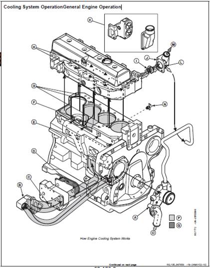
A—Coolant Pump F—Coolant Jacket K—Dual Thermostat Assembly O—Suction Side of Coolant
B—Coolant Passage Adapter G—Block Deck Passages L—Bypass Circuit Pump
C—Oil Cooler Drain Plug H—Passages M—To Radiator Top Tank P—High Temperature Coolant
D—Oil Cooler Plates I—Thermostat(s) N—Drain Valve Q—Low Temperature Coolant
E—Main Coolant Gallery J—Coolant
Manifold/Thermostat
Housing
NOTE: Two-valve head engine shown. Cooling of
four-valve head engine is similar.
The cooling system includes the radiator, coolant
pump (A), and thermostat(s) (I).
Coolant is circulated from the coolant pump into the
coolant passage adapter (B) and circulates around the
oil cooler plates (D). From the oil cooler, coolant flows
into the main coolant gallery (E). From the gallery
coolant flows into the coolant jacket (F), around the
cylinder liners, up through the block deck passages
(G), and into the cylinder head. In the cylinder head,
the coolant flows through passages (H) around the
intake and exhaust ports, valve seats, and injection
nozzles. Coolant flows toward the front end of the
cylinder head and exits through the coolant
manifold/thermostat housing (J). Engines may be
equipped with a dual thermostat assembly (K).
During the warm-up period, thermostat(s) (I) are closed
and coolant is directed through a bypass circuit (L) into
suction side of coolant pump. The coolant continues
circulating through the cylinder block, cylinder head,
and coolant pump to provide a uniform and fast
warm-up period.
Once the engine has reached operating temperature,
the thermostat(s) open and allow coolant to flow
through the upper radiator hose to the radiator top tank
(M). Coolant circulates through the radiator, dissipates
heat, and then flows out of the radiator through the
lower hose and into the suction side (O) of the coolant
pump. Coolant continues flowing through the engine
and radiator circuit until the coolant temperature drops
below the thermostat opening temperature.
The head gasket joint consists of the following
components:
· Cylinder head gasket
· Cylinder head (A)
· Cylinder block (E)
· Cylinder liners (C)
· Cylinder head cap screws (B)
The head gasket must form an air-tight seal between
cylinder liners and cylinder head that can withstand the
temperatures and pressures of the combustion process.
The gasket must also form a liquid-tight seal between the
cylinder head and cylinder block to retain coolant and oil
in their respective passages. The gasket (F) is
constructed of thin, formed sheets of steel-inserted,
non-asbestos material. The surface of gasket is treated to
improve liquid sealing and anti-stick characteristics. A fire
ring combustion seal (G) is located at each cylinder bore
and is held in place by a U-shaped stainless steel flange
(H).
The cylinder head and block must be flat to provide an
even clamping pressure over the entire surface of gasket,
and must have the proper surface finish to keep gasket
material from moving in the joint. Dowel pins (D) are used
to properly locate head gasket on block.
The cylinder liners must protrude evenly from top of
cylinder block the specified amount to provide adequate
clamping force on fire ring of each cylinder.
The cap screws must be proper length, made of proper
material, and be tightened to proper torque in order to
provide an adequate clamp load between other joint
components.
Each of the above components contributes to the integrity
of the head gasket joint. If any of these components do
not conform to specifications, gasket joint may fail,
resulting in combustion leaks, coolant leaks, or oil leaks.
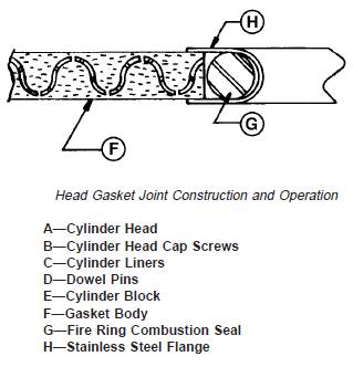
Head Gasket Joint Construction and
Operation
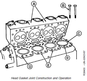
The head gasket joint consists of the following
components:
· Cylinder head gasket
· Cylinder head (A)
· Cylinder block (E)
· Cylinder liners (C)
· Cylinder head cap screws (B)
The head gasket must form an air-tight seal between
cylinder liners and cylinder head that can withstand the
temperatures and pressures of the combustion process.
The gasket must also form a liquid-tight seal between the
cylinder head and cylinder block to retain coolant and oil
in their respective passages. The gasket (F) is
constructed of thin, formed sheets of steel-inserted,
non-asbestos material. The surface of gasket is treated to
improve liquid sealing and anti-stick characteristics. A fire
ring combustion seal (G) is located at each cylinder bore
and is held in place by a U-shaped stainless steel flange
(H).
The cylinder head and block must be flat to provide an
even clamping pressure over the entire surface of gasket,
and must have the proper surface finish to keep gasket
material from moving in the joint. Dowel pins (D) are used
to properly locate head gasket on block.
The cylinder liners must protrude evenly from top of
cylinder block the specified amount to provide adequate
clamping force on fire ring of each cylinder.
The cap screws must be proper length, made of proper
material, and be tightened to proper torque in order to
provide an adequate clamp load between other joint
components.
Each of the above components contributes to the integrity
of the head gasket joint. If any of these components do
not conform to specifications, gasket joint may fail,
resulting in combustion leaks, coolant leaks, or oil leaks.
Operating conditions such as coolant, oil, and combustion
temperatures, and combustion pressures can reduce the
ability of the head gasket joint to function properly. Failure
of head gasket and mating parts may occur when coolant
and oil temperatures become excessive, or when
abnormally high combustion temperatures and pressures
persist.