 English
 Espaol
 Franais
 阿拉伯
阿拉伯 中文
中文 Deutsch
 Italiano
 Português
 日本
日本 韩国
韩国 български
 hrvatski
 esky
esky Dansk
Dansk Nederlands
 suomi
suomi Ελληνικ
 印度
印度 norsk
norsk Polski
 Roman
Roman русский
 Svenska
约翰迪尔强鹿柴油机涡轮增压器供应商,约翰迪尔强鹿柴油机涡轮增压器技术价格规格咨询服务,约翰迪尔强鹿柴油机涡轮增压器零配件供应,约翰迪尔强鹿柴油机涡轮增压器售后服务中心,约翰迪尔强鹿柴油机涡轮增压器,约翰迪尔强鹿柴油机涡轮增压器详细的技术参数,

产品中心
约翰迪尔强鹿柴油机涡轮增压器故障分析
详细描述
John Deere约翰迪尔强鹿柴油机涡轮增压器故障分析
CAUTION: After operating engine, allow exhaust
system to cool before removing turbocharger.
IMPORTANT: When cleaning turbocharger, do not
spray directly into compressor cover or
turbine housing. If turbocharger
inspection is required, do not clean
exterior prior to removal. Doing so may
wash away evidence of a potential
failure mode. See TURBOCHARGER
INSPECTION later in this group.)
1. Thoroughly clean exterior of turbocharger and
surrounding area to prevent entry of dirt into the air
intake system during removal.
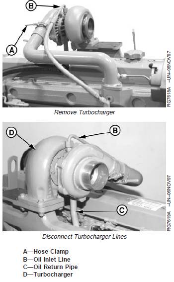
2. Remove air intake hose and exhaust elbow (shown
removed). Loosen hose clamp (A).
3. Disconnect oil inlet line (B) and oil return pipe (C) from
turbocharger (D).
4. Remove mounting cap screws and nuts and lift
turbocharger from exhaust manifold. Remove stainless
steel gasket.
5. Place turbocharger on a clean flat surface. Cap or plug
all air intake and exhaust openings.
6. Perform turbocharger inspection as described later, if
failure mode has not yet been determined. (See
TURBOCHARGER INSPECTION in this group.)
John Deere约翰迪尔强鹿柴油机涡轮增压器故障分析
Turbocharger Failure Analysis
The following is a guide for diagnosing the cause of
turbocharger failures after removal from the engine.
Problem Possible Cause Suggested Remedy
COMPRESSOR HOUSING INLET DEFECTS
Foreign Object Damage Objects left in intake system. Disassemble and inspect intake system for foreign
objects (this group).
Inspect engine for internal damage.
Leaking and/or defective intake system. Inspect air intake system connections including air
filter; repair as required (this group).
Inspect air intake related engine components.
Compressor Wheel Rub Bearing failure. Determine if engine and/or operator contributed to lack
of lubrication, contaminated lubrication, excessive
temperature, or debris generating engine failure in
progress. Correct as required.
Manufacturing defects. Correct as required (this group).
COMPRESSOR HOUSING OUTLET DEFECTS
Oil and/or Dirt in Housing Restricted air intake system. Inspect and clean air cleaner.
Prolonged periods of low rpm engine Check with operator to confirm conditions. (See
idling. Operator’s Manual.)
Defective oil seal ring. Repair as required (this group).
Restricted oil drain line. Inspect and clear oil drain line as required.
TURBINE HOUSING INLET DEFECTS
Oil in Housing Internal engine failure. Inspect and repair engine as required.
Oil leaking from compressor housing Verify that oil is in compressor housing and refer to
seal. “Compressor Housing Outlet Defects” as listed earlier
in this chart.
Center Wall Deteriorated Excessive operating temperature. Check for restricted air intake.
Check engine for overfueling.
Check injection pump timing.
TURBINE HOUSING OUTLET DEFECTS
Turbine Wheel Rub Bearing failure. Determine if engine and/or operator contributed to lack
of lubrication, contaminated lubrication, excessive
temperature, or debris generating engine failure in
progress. Correct as required.
Manufacturing defect. Correct as required (this group).
Foreign Object Damage Internal engine failure. Inspect and repair engine as required.
Objects left in intake system. Disassemble and inspect air intake system (this
group).
Leaking air intake system. Correct as required (this group).
Oil and/or Excessive Carbon Internal engine failure. Verified by oil in turbine housing. Correct as required.
Turbine seal failure. Inspect for excessive heat from overfueling and/or
restricted air intake.
Prolonged periods of low rpm engine Ask operator to run engine under load or at a higher
idling. rpm (see Operator’s Manual).
Restricted oil drain line. Inspect and clear oil drain line as required.
EXTERNAL CENTER HOUSING AND JOINT DEFECTS
Leaks from Casting Defective casting. Replace turbocharger (this group).
Defective gasket. Verify if leaks are occurring at gasket joints.
Leaks from Joints Loose attaching screws. Tighten to specifications (this group).
Defective gasket. Inspect and repair as required.
INTERNAL CENTER HOUSING DEFECTS
Excessive Carbon Build-Up in Housing Hot engine shutdown. Review proper operation with operator as shown in
or on Shaft operator’s manual.
Excessive operating temperature. Restricted air intake; overfueling or mistimed engine.
Restricted oil drain line. Inspect and clean oil drain lines as required.
Operating engine at high speeds and Idle engine for a few minutes to allow oil to reach
loads immediately after start-up. bearings before applying heavy loads.
Turbocharger Inspection
The following inspection procedure is recommended for
systematic failure analysis of a suspected failed
turbocharger. This procedure will help to identify when a
turbocharger has failed, and why it has failed, so the
primary cause of the failure can be corrected.
Proper diagnosis of a non-failed turbocharger is important
for two reasons. First, identification of a non-failed
turbocharger will lead to further investigation and repair of
the cause of a performance complaint.
Second, proper diagnosis eliminates the unnecessary
expense incurred when a non-failed turbocharger is
replaced.
The recommended inspection steps, which are explained
in detail on following pages, are:
· Compressor Housing Inlet and Compressor Wheel.
· Compressor Housing Outlet.
· Turbine Housing Inlet.
· Turbine Housing Outlet and Turbine Wheel.
· External Center Housing and Joints.
· Perform Axial Bearing End Play Test
NOTE: To enhance the turbocharger inspection, an
inspection sheet (Form No. DF-2280 available
from Distribution Service Center—English only)
can be used that lists the inspection steps in the
proper order and shows potential failure modes
for each step. Check off each step as you
complete the inspection and record any details or
problems obtained during inspection. Retain this
with the work order for future reference.
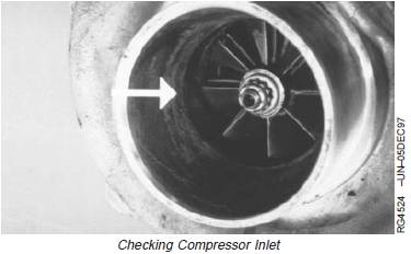
Compressor Housing Inlet and Compressor Wheel
1. Check compressor inlet and compressor wheel (A) for
foreign object damage.
NOTE: Foreign object damage may be extensive or
minor. In either case, the source of the foreign
object must be found and corrected to eliminate
further damage.
2. Mark findings on your checklist and continue the
inspection.
A—Compressor Wheel

NOTE: You will need a good light source for this check.
3. Check compressor inlet for wheel rub on the housing
(arrow). Look very closely for any score marks on the
housing itself and check the tips of the compressor
wheel blades for damage.
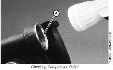
Compressor Housing Outlet
1. Check compressor housing outlet (A). The outlet
should be clean and free of dirt or oil.
2. Mark it on your checklist if dirt or oil is found and
continue the inspection.
A—Compressor Housing Outlet
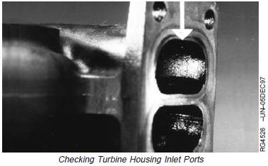
Turbine Housing Inlet
Check the turbine housing inlet ports (arrow) for oil in
housing, excessive carbon deposit or erosion of center
walls.
NOTE: If the inlet is wet with oil, or has excessive carbon
deposits, an engine problem is likely. Center wall
erosion (cracking or missing pieces), indicates
excessive exhaust temperature.
Turbine Housing Outlet and Turbine Wheel
1. Use a flashlight to look up inside the turbine housing
outlet (A) and check blades (B) for foreign object
damage.
A—Turbine Housing Outlet
B—Blades
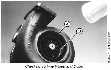
2. Inspect the wheel blades and housing for evidence of
wheel rub (arrow). Wheel rub can bend the tips of the
blades with the housing showing wear or damage.

3. Rotate the shaft, using both hands, to check rotation
and clearance. The shaft should turn freely; however,
there may be a slight amount of drag.
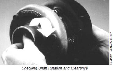
IMPORTANT: Use only moderate hand force (3—
4 pounds) on each end of shaft.
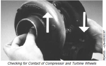
4. Next, pull up on the compressor end of the shaft and
press down on the turbine end while rotating shaft.
Neither the compressor wheel nor the turbine wheel
should contact the housing at any point.
NOTE: There will be some “play” because the bearings
inside the center housing are free floating.
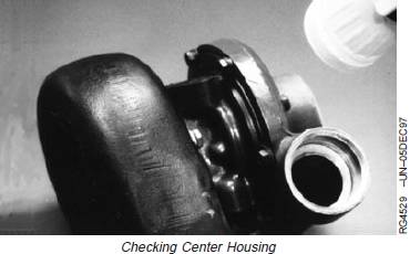
External Center Housing and Joints
Visually check the outside of the center housing, all
connections to the compressor, and turbine housing for
oil.
NOTE: If oil is present, make sure it is not coming from a
leak at the oil supply or return line.
IMPORTANT: Before you finalize your conclusion that
the turbocharger has not failed, it is
strongly recommended that the
following procedures of checking radial
bearing clearance and axial bearing
endplay with a dial indicator be
performed. These procedures are not
required if a failure mode has already
been identified.
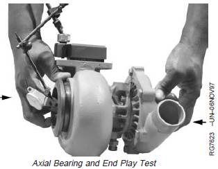
Perform Axial Bearing End Play Test
This test will give an indication of the condition of the axial
bearing within the center housing and rotating assembly.
1. Mount magnetic base dial indicator so that indicator tip
rests on end of shaft. Preload indicator tip and zero
dial on indicator.
2. Move shaft axially back and forth by hand.
3. Observe and record total dial indicator movement.
Specification
Turbocharger
(AiResearch/Garret)—Axial
Bearing End Play 0.025—0.102 mm
(0.001—0.004 in.)
..........................................................
Turbocharger (CZ)—Axial Bearing
End Play 0.11—0.16 mm
(0.004—0.006 in.)
............................................................................
Turbocharger (Schwitzer)—Axial
Bearing End Play 0.064—0.114 mm
(0.0025—0.0045 in.)
..........................................................
Turbocharger
(BorgWarner/Schwitzer)—Axial
Bearing End Play ..................................... 0.14 mm (0.0055 in.) Maximum
If bearing end play is not within specification, replace
turbocharger.
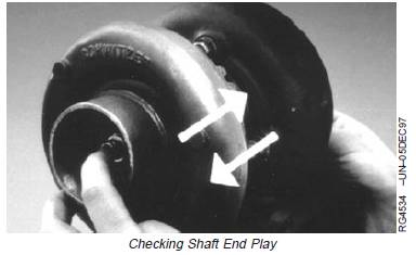
4. Next, check shaft endplay by moving the shaft back
and forth (white arrows) while rotating. There will be
some endplay but not to the extent that the wheels
contact the housings.
NOTE: These diagnostic procedures will allow you to
determine the condition of the turbocharger. If the
turbocharger has failed, analysis of your
inspection notes should direct you to the specific
areas of the engine to correct the problems
causing the turbocharger failure. See
TURBOCHARGER FAILURE ANALYSIS outlined
earlier in this group. It is not unusual to find that a
turbocharger has not failed. If your turbocharger
passes all the inspections, the problem lies
somewhere else.
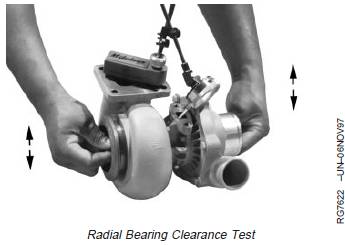
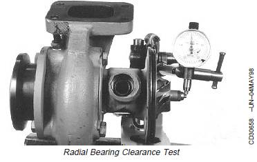
Perform Radial Bearing Clearance Test
This test will give an indication of the condition of the
radial bearings within the center housing and rotating
assembly.
NOTE: Prelube center housing bearings prior to
performing radial clearance test. (See PRELUBE
TURBOCHARGER, later in this group.)
AiResearch/Garret Turbocharger
1. Position dial indicator with extension adapter onto
center housing so that tip rests on shaft extending
through oil return cavity.
IMPORTANT: Use only moderate force (3—4 lb) on
each end of the shaft when checking
clearance.
2. Grasp rotating shaft at both ends and move the shaft
toward the indicator then away from the indicator
(arrows) by applying moderate force of 3—4 lb.
3. Observe and record total indicator movement.
Specification
Bearing Clearance............................... 0.08—0.18 mm (0.003—0.007 in.)
4. If total indicator reading is not within specification,
replace turbocharger.
BorgWarner/Schwitzer and CZ Turbochargers
1. Remove compressor cover.
2. Install a dial indicator against end of shaft as shown.
3. Move shaft alternately toward and away from indicator
and record total travel. Compare reading with the
following specification.
Specification
Turbocharger (CZ)—Radial
Bearing Clearance............................... 0.37—0.46 mm (0.015—0.018 in.)
Turbocharger
(BorgWarner/Schwitzer)—Radial
Bearing Clearance.................................... 0.51 mm (0.0200 in.) Maximum
4. If total indicator reading is not within specification,
replace turbocharger.
5. Install compressor cover.
Adjust Turbocharger Wastegate Actuator (If
Equipped)
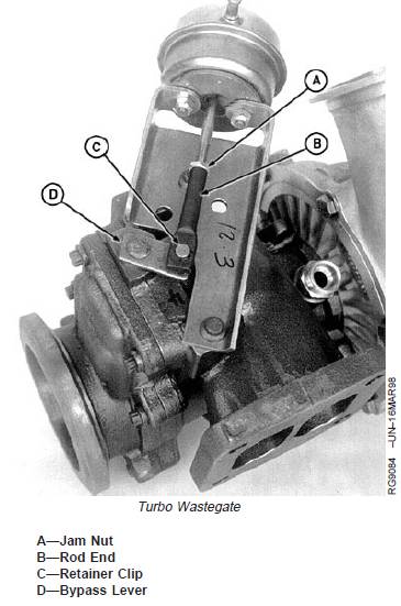
A—Jam Nut
B—Rod End
C—Retainer Clip
D—Bypass Lever
1. Loosen jam nut (A).
2. Disconnect hose and pressurize actuator to 83 kPa
(.83 bar) (12 psi) and hold at this calibration pressure.
3. Push bypass lever (D) as far as possible toward the
actuator and apply pressure to keep lever in that
position.
IMPORTANT: Twisting or forcing the entire rod in or
out will change the calibration, causing
damage to engine from overboost.
4. Turn rod end (B) in either direction until rod eye can
just be slipped over bypass lever pin. Loosen rod end
an additional half turn, install onto pin and secure with
retainer clip (C). Release pressure on actuator.
5. Pressurize the actuator to 83 kPa (.83 bar) (12 psi).
Measure the end play with a dial indicator, moving the
bypass assembly back and forth in a direction
perpendicular to the actuator rod. End play should be
within specifications listed. If necessary to adjust, set
end play at 0.38 mm (0.015 in.)
Specification
Turbocharger—Actuator End Play 0.05—0.056 mm
(0.002—0.022 in.)
...................................
6. Vary the pressure from 62—83 kPa (.62—.83 bar) (9—
12 psi) a few times to verify smooth and free operation
of the bypass assembly.
7. Attach hose to actuator and secure with hose clamp.
Repair Turbocharger
Turbochargers used on the engines covered in this
manual are available through service parts as a complete
remanufactured assembly only. Individual components for
repair are not available.
Prelube Turbocharger
IMPORTANT: DO NOT spin the rotor assembly with
compressed air. Damage to bearings
can occur when using compressed air.
Fill oil inlet or drain port with clean engine oil and spin
rotating assembly (by hand) to properly lubricate bearings.
If turbocharger is to be stored for an extended period of
time, lubricate internally and install protective covers on all
openings.

John Deere约翰迪尔强鹿柴油机安装涡轮增压器
IMPORTANT: If turbocharger failed because of foreign
material entering the air intake system,
be sure to examine the system and
clean as required to prevent a repeat
failure.
If not done previously, prime (prelube) the turbocharger
rotating assembly prior to mounting turbocharger on
engine. Prelube center housing with clean engine oil
through the oil drain hole. Turn rotating assembly by hand
to lubricate bearings.
IMPORTANT: Turbochargers can be either single or
dual entry. Make sure the appropriate
single or dual gasket is used when
installing turbocharger.
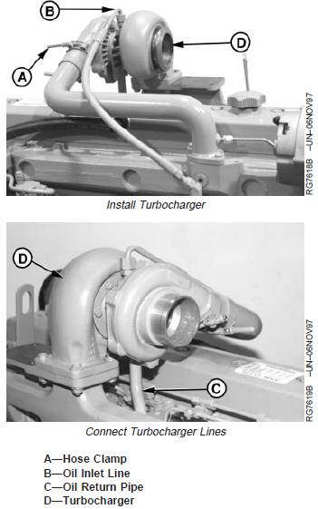
1. Position turbocharger (D) and new stainless steel
gasket onto exhaust manifold. Tighten stud nuts to
specifications.
Specification
Turbocharger-to-Exhaust Manifold
Nuts—Torque .................................................................. 70 N•m (52 lb-ft)
2. Install oil return pipe (C) to turbocharger. Tighten oil
return pipe cap screws to specifications.
Specification
Turbocharger Oil Return Pipe
Cap Screws—Torque ...................................................... 24 N•m (18 lb-ft)
3. Connect turbocharger oil inlet line (B) and tighten to
specifications.
Specification
Turbocharger Oil Inlet Line (At
Turbocharger)—Torque................................................... 24 N•m (18 lb-ft)
Turbocharger Oil Inlet Line (At Oil
Filter Header)—Torque.................................................... 24 N•m (18 lb-ft)
4. Connect air inlet hose-to-turbocharger compressor
housing. Tighten hose clamp (A) on air inlet line to
specifications.
Specification
Turbocharger Air Inlet Hose
Clamp—Torque ................................................ 6 N•m (4.5 lb-ft) (54 lb-in.)
IMPORTANT: Since the greatest suction force occurs
between air cleaner and turbocharger,
ensure that hose connections are tight
to prevent entry of dirt into system.
5. Install exhaust adapter and exhaust elbow. Tighten cap
screws and clamp to specifications.
Specification
Exhaust Adapter-to-Turbocharger
Clamp—Torque ............................................. 7.5 N•m (5.5 lb-ft) (66 lb-in.)
Turbocharger Exhaust Elbow—
Torque ............................................................................. 47 N•m (35 lb-ft)
Turbocharger Break-In
IMPORTANT: A new or repaired turbocharger DOES
NOT have an adequate oil supply for
immediate start-up of engine. Perform
the steps below to prevent damage to
turbocharger bearings.
1. Either push the throttle lever to the “STOP” position,
hold the engine shut-off knob out, or disconnect
electrical wire from injection pump.
IMPORTANT: DO NOT crank engine longer than 30
seconds at a time to avoid damage to
starter motor.
2. Crank engine over with starter motor until oil pressure
gauge needle registers within the “GREEN” zone of
pressure gauge.
3. Start and run engine at low idle while checking oil inlet
and air piping connections for leaks.
Recommendations for Turbocharger Use
IMPORTANT: Should the engine stall when operating
under load, IMMEDIATELY restart the
engine to prevent overheating of
turbocharger parts.
In most cases, turbocharger damage is caused by
improper start-up and shutdown procedures. Always idle
the engine for at least 30 seconds (no load) after start-up
and before shutdown.
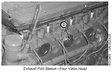
John Deere约翰迪尔强鹿柴油机拆卸,检查和安装排气
1. Remove turbocharger (if equipped), exhaust elbow, or
exhaust pipe if desired. Turbocharger can be removed
with exhaust manifold (A). (See REMOVE
TURBOCHARGER, earlier in this group.)
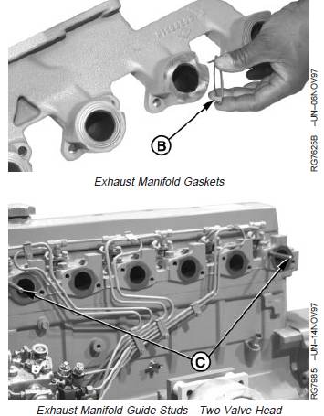
2. Remove exhaust manifold. Two-Valve head have guide
studs (C) to aid in removal.
NOTE: Some engines are assembled with sealant in
production. Replace with gaskets when servicing.
Some exhaust manifolds are equipped with a
one-piece gasket.
3. Remove gasket(s) (B) if equipped.
4. Remove exhaust port sleeves on four-valve head.
5. Inspect sleeves for cracks or wear. Replace as
needed.
6. Clean mating surfaces of cylinder head and exhaust
manifold with cleaning solvent, acetone, or any other
suitable cleaner that will remove sealant, if previously
applied. (Brake Kleen, Ignition Cleaner and Drier are
examples of commercially available solvents that will
remove sealant from flange.) Thoroughly clean
passages in exhaust manifold.
7. Inspect each exhaust manifold for cracks or damage.
Inspect machined mounting surfaces for burrs or other
defects which might prevent gasket(s) from sealing
properly. Replace parts as needed.
8. Install gasket(s) (B) on exhaust manifold.
NOTE: Stainless steel gaskets can be reused if not
damaged. Graphite gaskets must be replaced.
9. Install exhaust port sleeves for four-valve head.
A—Exhaust Manifold
B—Gasket
C—Guide Studs
D—Exhaust Port Sleeve
10. Install exhaust manifold. Use guide studs (C) if
equipped.
11. Apply PT569 NEVER-SEEZâ Compound to cap
screws.
12. Tighten exhaust manifold-to-cylinder head cap screws
to specifications. On 6-cylinder engines, tighten cap
screws on No. 3 and No. 4 cylinders first. On
4-cylinder engines, tighten No. 2 and No. 3
cylinders first.
Specification
Exhaust Manifold-to-Cylinder
Head Cap Screws—Torque ........................................... 70 N•m (52 lb-ft)
Remove and Install Air-to-Air Aftercooler
Refer to machine technical manual for removal,
inspection, and installation procedures.
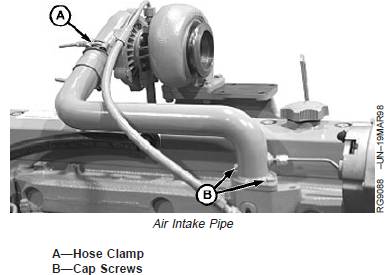
Remove and Install Air Intake Pipe
NOTE: Configuration of air intake pipe varies by
application. Engines may also be equipped with
an air heater or spacer between intake pipe and
manifold. (See REMOVE AND INSTALL AIR
HEATER next in this group.)
1. If required, disconnect start aid lines or wiring.
2. Remove cap screws (B).
3. Loosen hose clamp (A) and remove air intake pipe.
4. Inspect and repair as required.
5. Install new gasket and air intake pipe. Tighten cap
screws to specifications.
Specification
Air Intake Pipe-to-Cylinder
Head—Torque ................................................................. 70 N•m (52 lb-ft)
6. Tighten hose clamp (A) to specifications.
Specification
Air Intake Pipe Hose Clamp—
Torque .............................................................. 6 N•m (4.5 lb-ft) (54 lb-in.)
7. If required, connect start aid lines or wiring.
John Deere约翰迪尔强鹿柴油机拆卸、检查和安装进气歧管
NOTE: position of fuel filters vary by engine type and
engine application.
1. Remove fuel line (A).
2. Remove two cap screws (B) and remove prefilter (C).
3. Remove twelve cap screws (D) and remove intake
manifold (E).
4. Inspect for cracks or damage. Inspect machined
mounting surfaces for burrs or other defects which
might prevent gasket from sealing properly.
5. Install new gasket and install intake manifold. Tighten
cap screws to specification.
Specification
Intake Manifold Cap Screws—
Torque ............................................................................. 73 N•m (54 lb-ft)
6. Install prefilter.

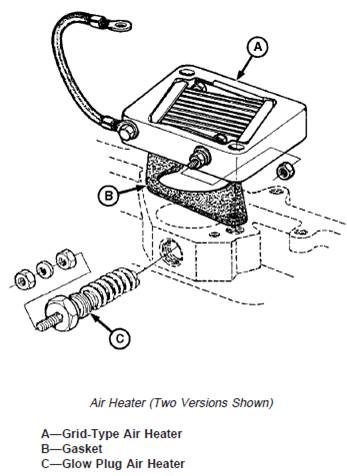
拆卸和安装空气加热器
NOTE: Figure shows two types of air heaters. One or the
other is used per application.
On later model grid-type air heaters, gasket (B) is
replaced by an O-ring, eliminating the need for
ground wire shown.
1. Disconnect wiring, if required.
2. If machine is equipped with grid-type air heater (A),
remove air intake pipe. (See REMOVE AND INSTALL
AIR INTAKE PIPE in this group.)
3. Remove air heater (A) or (C).
4. Replace parts as required.
5. If equipped with grid-type air heater, install air heater
(A) with new gasket (B) or O-ring.
Coat threads of air heater (C) with LOCTITEâ 592 Pipe
Sealant with TEFLONâ and install.
6. Install air intake pipe if required.
7. Connect wiring, if required.
拆卸和安装起动辅助装置(如果装备)
1. Disconnect starting aid tube (1).
NOTE: When removing nozzle, note the location of red
dot (2) when removing.
2. Remove nozzle holder from air inlet.
3. Clean or replace nozzle holder as required.
4. If removed, install adapter into air inlet tube and torque
to specifications.
Specification
Adapter-to-Air Inlet Tube—Torque.................................. 50 N•m (37 lb-ft)
NOTE: Red dot (2) on nozzle holder must be installed at
the 12 o’clock position, facing the incoming air
flow. Nozzle orifice (3) needs to be in the path of
the air flow to disperse fluid for quick start of
engine.
5. Install nozzle and connect starting aid tube.
1—Starting Aid Tube Nozzle Holder
2—Red Dot for Nozzle Installation
3—Orifice
