English
 Espaol
 Franais
 阿拉伯
阿拉伯 中文
中文 Deutsch
 Italiano
 Português
 日本
日本 韩国
韩国 български
 hrvatski
 esky
esky Dansk
Dansk Nederlands
 suomi
suomi Ελληνικ
 印度
印度 norsk
norsk Polski
 Roman
Roman русский
 Svenska
John Deere强鹿柴油机机油冷却器的拆卸安装与油压力调节阀技术参数规范供应商,John Deere强鹿柴油机机油冷却器的拆卸安装与油压力调节阀技术参数规范技术价格规格咨询服务,John Deere强鹿柴油机机油冷却器的拆卸安装与油压力调节阀技术参数规范零配件供应,John Deere强鹿柴油机机油冷却器的拆卸安装与油压力调节阀技术参数规范售后服务中心,John Deere强鹿柴油机机油冷却器的拆卸安装与油压力调节阀技术参数规范,John Deere强鹿柴油机机油冷却器的拆卸安装与油压力调节阀技术参数规范详细的技术参数,

产品中心
John Deere强鹿柴油机机油冷却器的拆卸安装与油压力调节阀技术参数规范
详细描述
John Deere约翰迪尔强鹿柴油机机油冷却器的拆卸安装与油压力调节阀技术参数规范
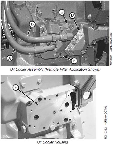
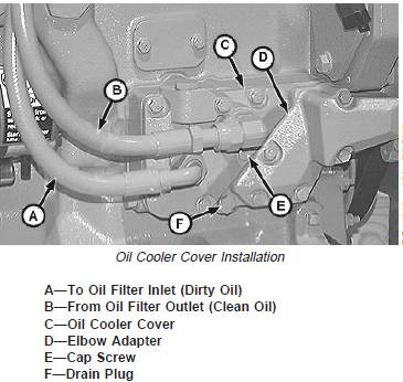
1. Remove oil cooler drain plug (E) and drain coolant.
2. On high mount, rear and front mount oil filters, remove
oil filter header with tubes and adapter/cooler cover, if
equipped. (See REMOVE, INSPECT, AND INSTALL
OIL FILTER BASE, in this group.)
3. On left hand or remote oil filters, disconnect oil lines
(A) and (B) and remove cooler cover (C).
4. If equipped, disconnect line from top of oil cooler
housing.
5. Remove elbow adapter (D).
6. Remove housing (F).
7. Remove oil cooler (G).
A—To Oil Filter Inlet (Dirty Oil)
B—From Oil Filter Outlet (Clean Oil)
C—Cover
D—Adapter
E—Oil Drain Plug
F—Oil Cooler Housing
G—Oil Cooler
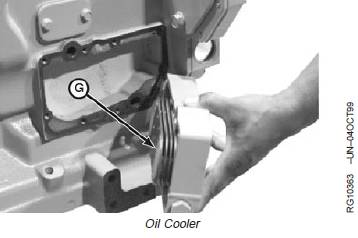
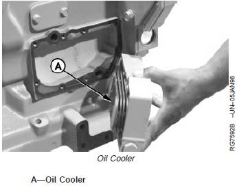
Inspect Oil Cooler Assembly
1. Inspect oil cooler (A) (shown installed in housing) for
physical damage, plugging, or leakage which may
allow mixing of oil and coolant.
2. Back flush oil cooler to clean all debris from core.
3. Pressure test oil cooler in liquid and compressed air if
mixing of oil and coolant is suspected.
Oil cooler should show no leakage when 140—170
kPa (1.4—1.7 bar) (20—25 psi) air pressure is applied
for a minimum of 30 seconds.
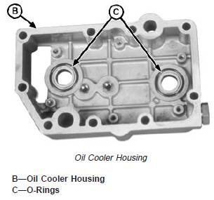
4. Inspect oil cooler housing (B).
NOTE: Service oil cooler housings have a 3.5 mm (0.138
in.) O-ring groove width. Older housings had a 4.5
mm (0.177 in.) groove width. Check O-ring
grooves for latest width specification and replace
if necessary.
5. Remove O-rings (C) and inspect surface finish of
O-ring grooves. If there are ridges discernible with a
fingernail, replace oil cooler housing. Additionally, if
there is porosity in grooves larger than 0.5 mm (0.20
in.), replace housing.
6. Replace parts as needed. DO NOT attempt to repair oil
cooler.
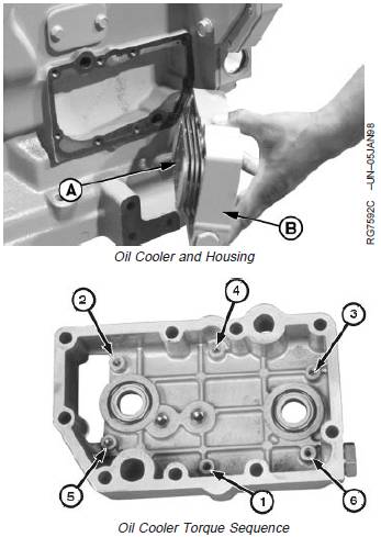
Install Oil Cooler Assembly
1. Lubricate new O-rings with clean engine oil.
2. Install oil cooler (A) in oil cooler housing (B).
3. Apply LOCTITEâ 242 Thread Lock and Sealer (Medium
Strength) to six Allen head cap screws and install oil
cooler in housing. Tighten all cap screws by hand, then
tighten to the following specifications in sequence
shown.
Specification
Oil Cooler-to-Housing Allen Head
Cap Screws—Torque ................................................... 12 N•m (106 lb-in.)
A—Oil Cooler
B—Oil Cooler Housing
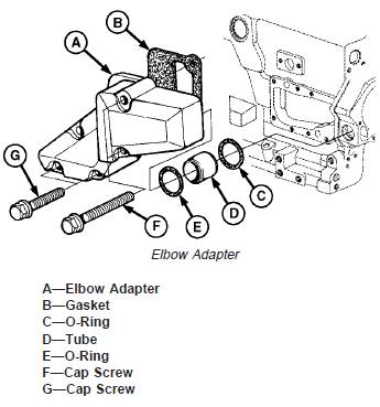
4. On high mount, rear and front mount applications:
Use new gaskets and install oil cooler assembly. Be
sure gasket is properly aligned with cap screw holes.
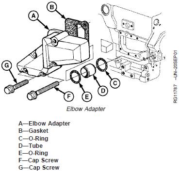
NOTE: On earlier engines, tube (D) is part of elbow
adapter (A) and O-ring (E) is not used.
5. Install gasket (B), O-rings (C and E), tube (D) and
elbow adapter (A). Install cap screws (F and G) to
attach elbow adapter to engine. Tighten cap screws to
specification.
Specification
Oil Cooler Elbow Adapter Cap
Screws—Torque.............................................................. 35 N•m (26 lb-ft)
6. If equipped, install line fitting on top of oil cooler
housing and tighten to specification. Install new O-ring
and connect oil line to fitting and tighten to
specification.
Specification
Line Fitting on Top of Oil Cooler
Housing—Torque............................................................ 50 N •m (37 lb-ft)
Oil Line Clamp on Top of Oil
Cooler Housing—Torque................................................ 7 N •m (62 lb-in.)
NOTE: Refer to Parts Catalog for appropriate
replacement parts as necessary.
7. Install parts (A, B, E and F). (See REMOVE, INSPECT
AND INSTALL OIL FILTER BASE in this group.)
8. Apply LOCTITEâ 242 Thread Lock and Sealer (Medium
Strength) to cap screws (D) and install. Tighten cap
screws to specification.
Specification
Oil Cooler Cover Cap Screws—
Torque ............................................................................. 35 N•m (26 lb-ft)
A—Turbocharger Oil Inlet Line
B—Tubes
C—Elbow Adapter
D—Cap Screw
E—Oil Tube Adapter/Oil Cooler Cover
F—Oil Filter Header/Rear Adapter

9. On left hand or remote filter applications: Use new
gaskets and install oil cooler assembly. Be sure gasket
is properly aligned with cap screw holes.
NOTE: On earlier engines, tube (D) is part of elbow
adapter (A) and O-ring (E) is not used.
10. Install gasket (B), O-rings (C and E), tube (D) and
elbow adapter (A). Install cap screws (F and G) to
attach elbow adapter to engine. Tighten cap screws
to specification.
Specification
Oil Cooler Elbow Adapter Cap
Screws—Torque.............................................................. 35 N•m (26 lb-ft)
11. Install oil cooler cover (C).
12. Apply LOCTITEâ 242 Thread Lock and Sealer
(Medium Strength) to cap screws (E) and install.
Tighten cap screws to specifications.
Specification
Oil Cooler Cover Cap Screws—
Torque ............................................................................. 35 N•m (26 lb-ft)
13. If equipped, install line fitting on top of oil cooler
housing and tighten to specification. Install new O-ring
and connect oil line to fitting and tighten to
specification.
Specification
Line Fitting on Top of Oil Cooler
Housing—Torque............................................................ 50 N •m (37 lb-ft)
Oil Line Clamp on Top of Oil
Cooler Housing—Torque................................................ 7 N •m (62 lb-in.)
14. Connect lines (A) and (B) and tighten to
specifications.
Specification
Oil Cooler Line End Nuts
(Remote Filter Applications)—
Torque ............................................................................. 66 N•m (49 lb-ft)
15. For all applications: Install oil cooler drain plug (F)
and tighten to specifications.
Specification
Oil Cooler Drain Plug—Torque ........................................ 5 N•m (60 lb-in.)
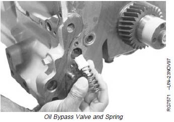
Remove, Inspect, and Install Oil Bypass
Valve
1. Remove timing gear cover and front plate.
(SeeREMOVE TIMING GEAR COVER in Group 050.
See REMOVE CYLINDER BLOCK FRONT PLATEin
Group 050.)
2. Remove oil bypass valve and spring.
3. Inspect valve and spring for damage. Replace parts if
necessary.
4. Check bypass valve spring free length and
compression strength using D01168AA Spring
Compression Tester. Replace parts if not within
specification.
Specification
Oil Bypass Valve Springs—Free
Length.............................................................................. 51 mm (2.00 in.)
Spring Load at 29 mm (1.14 in.)
Compressed Length .................................................... 87.8 N (20 lb-force)
5. Install oil bypass valve and spring in cylinder block.
6. Install front plate and timing gear cover. (See INSTALL
TIMING GEAR COVER in Group 050. See INSTALL
CYLINDER BLOCK FRONT PLATE in Group 050.)
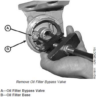
Remove and Install Oil Filter Bypass Valve
(Extended-Life Filter)
NOTE: Bypass valve MUST be replaced any time
damage is noticed or it is removed from filter
base.
1. Remove oil filter base. (See REMOVE, INSPECT, AND
INSTALL OIL FILTER BASE in this group.)
NOTE: Valve plunger will need to be slightly compressed
to insert puller.
2. Remove bypass valve (A) from filter base (B) using
D01061AA Blind-Hole Puller Set, or equivalent blind
hole puller.
3. Clean filter base and inspect for damage. Replace if
necessary.
4. Press in new bypass valve until seated using an
appropriate arbor.
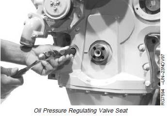
Remove and Install Oil Pressure Regulating
Valve
NOTE: On earlier engines, the oil pressure regulating
valve, spring and seat are separate parts located
under a plug on the timing gear cover.
On later engines, the oil pressure regulating valve
is a one-piece cartridge. No valve seat is used.
Refer to the appropriate following procedures.
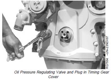
Remove and Install Oil Pressure Regulating Valve and
Seat (Earlier Engines)
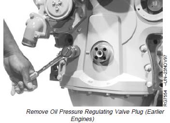
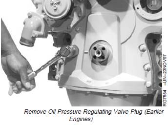
1. Remove oil pressure regulating valve plug from timing
gear cover.
John Deere约翰迪尔强鹿柴油机拆卸和安装机油压力调节阀
NOTE: On earlier engines, the oil pressure regulating
valve, spring and seat are separate parts located
under a plug on the timing gear cover.
On later engines, the oil pressure regulating valve
is a one-piece cartridge. No valve seat is used.
Refer to the appropriate following procedures.
Remove and Install Oil Pressure Regulating Valve and
Seat (Earlier Engines)
1. Remove oil pressure regulating valve plug from timing
gear cover.
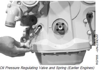
2. Remove oil pressure regulating valve and spring.
3. Check valve cone for excessive wear and damaged
sealing face.
NOTE: When ordering early style oil pressure regulating
valve parts, they may be substituted with a later
cartridge style oil pressure regulating valve as it
becomes available for service. (See REMOVE
AND INSTALL OIL PRESSURE REGULATING
VALVE (LATER ENGINES) in this procedure for
installation.)
4. Check oil pressure regulating spring free length and
compression strength using D01168AA Spring
Compression Tester. Replace parts if not within
specification.
Oil Pressure Regulating Valve Spring Specifications—
Specification
4-Cylinder Engines (Except for
Saran Engines Listed Below)—
Spring Free Length .................................................... 115.5 mm (4.55 in.)
4-Cylinder Engines (Except for
Saran Engines Listed Below)—
Spring Load at 42.5 mm
(1.68 in.) ............................................... 40.5—49.4 N (9.1—11.1 lb-force)
6-Cylinder Engines and
CD4045HF157/158,
CD4045TF157/158 and
CD4045TF257/258—Spring Free
Length............................................................................ 119 mm (4.68 in.)
6-Cylinder Engines and
CD4045HF157/158,
CD4045TF157/158 and
CD4045TF257/258—Spring Load
at 42.5 mm
(1.68 in.) 60.1—73.4 N (13.5—16.5
lb-force)
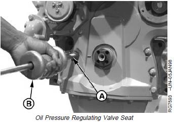
IMPORTANT: The valve seat is destroyed during
valve seat removal. If the valve seat is
removed, the oil pressure regulating
valve will need to be replaced.
5. Pull valve seat out of cylinder block with JT01727
Collet (A) and JT01718 Slide Hammer (B) from
D01061AA Blind-Hole Puller Set, or equivalent.
A—JT01727 Collet
B—JT01718 Slide Hammer
IMPORTANT: DO NOT drive against raised inner rim
of valve seat so that valve seat bore is
not damaged.
6. Drive valve seat into cylinder block with JD248A
(JD-248A) Oil Pressure Relief Valve Bushing Driver
and JDG536 (OTC813) Handle until the seat bottoms
in bore.
7. Install valve, spring, washer, and plug in timing gear
cover. Tighten plug to specification.
Specification
Oil Pressure Regulating Valve—
Torque ............................................................................. 95 N•m (70 lb-ft)
Remove and Install Oil Pressure Regulating Valve
(Later Engines)
IMPORTANT: If replacing a valve on an earlier engine
with a valve seat, with a later cartridge
style valve, remove valve seat before
installing new valve. (See REMOVE AND
INSTALL OIL PRESSURE REGULATING
VALVE AND SEAT (EARLIER ENGINES)
previously in this procedure.)
1. Remove timing gear cover. (See REMOVE TIMING
GEAR COVER in Group 050.)
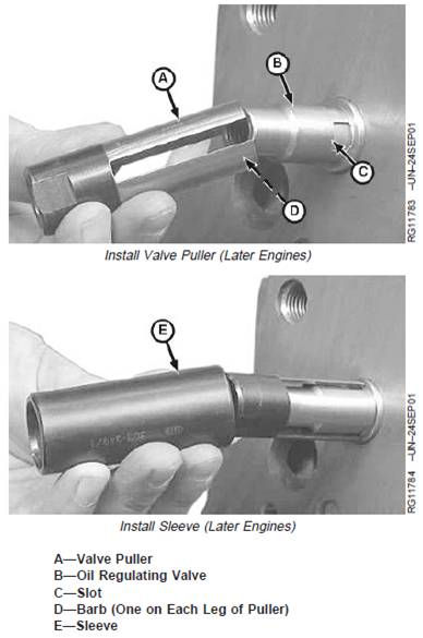
2. Install valve puller (A) (part of JDG1517 Pressure
Regulating Valve Installer and Remover Tool Set) on
oil regulating valve (B). Make sure barbs (D) lock into
slots (C) of valve.
3. Slide sleeve (E) (part of JDG1517 Pressure Regulating
Valve Installer and Remover Tool Set) completely over
valve puller.
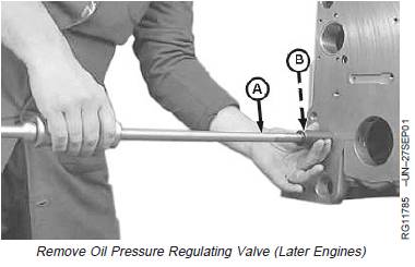
4. Install JT01718 Slide Hammer (A) into threaded end of
valve puller (B) and remove the valve from the engine
block.
5. To remove the valve puller from the oil regulating
valve, first remove the sleeve and slightly rotate the
puller on the valve. This will cause the puller to come
out of the valve slots so it can be removed. (There is a
chamfer on the inside of each leg, allowing the valve
puller to be easily rotated.)
A—Slide Hammer
B—Valve Puller
NOTE: It is recommended to replace cartridge style
valves only after engine front plate is installed.
Front plate mounting studs will help protect valve
from damage.
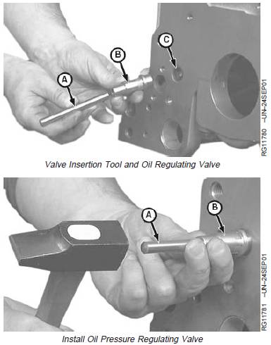
6. To install the oil pressure regulating valve, insert valve
insertion tool (A) (part of JDG1517 Pressure
Regulating Valve Installer and Remover Tool Set) into
oil pressure regulating valve (B). Use a hammer to
drive the valve into bore (C) of engine block until fully
seated.
A—Valve Insertion Tool
B—Oil Pressure Regulating Valve
C—Hole in Engine Block