English
 Espaol
 Franais
 阿拉伯
阿拉伯 中文
中文 Deutsch
 Italiano
 Português
 日本
日本 韩国
韩国 български
 hrvatski
 esky
esky Dansk
Dansk Nederlands
 suomi
suomi Ελληνικ
 印度
印度 norsk
norsk Polski
 Roman
Roman русский
 Svenska
John Deere强鹿柴油机正时齿轮间隙的测量与凸轮轴的标准值参数供应商,John Deere强鹿柴油机正时齿轮间隙的测量与凸轮轴的标准值参数技术价格规格咨询服务,John Deere强鹿柴油机正时齿轮间隙的测量与凸轮轴的标准值参数零配件供应,John Deere强鹿柴油机正时齿轮间隙的测量与凸轮轴的标准值参数售后服务中心,John Deere强鹿柴油机正时齿轮间隙的测量与凸轮轴的标准值参数,John Deere强鹿柴油机正时齿轮间隙的测量与凸轮轴的标准值参数详细的技术参数,

产品中心

John Deere强鹿柴油机正时齿轮间隙的测量与凸轮轴的标准值参数
详细描述
John Deere约翰迪尔强鹿柴油机正时齿轮间隙的测量与凸轮轴的标准值参数
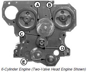
NOTE: All gears have helical cut teeth.Measure timing gear backlash. Compare against thefollowing specifications.
Timing Gear Backlash Specifications—Specification
Camshaft-to-Upper Idler (A)
(Two-Valve Head Engine)—Backlash 0.04—0.2 mm(0.0015—0.008 in.)
Camshaft-to-Upper Idler (A)
(Four-Valve Head Engine)—Backlash 0.03—0.64 mm(0.0011—0.0254 in.)
Injection Pump-to-Upper Idler (B)
(Two-Valve Head Engine)—Backlash 0.04—0.2 mm(0.0015—0.008 in.)
Injection Pump-to-Upper Idler (B)
(Four-Valve Head Engine)—Backlash 0.09—0.55 mm(0.0034—0.0218 in.)
Upper Idler-to-Crankshaft (C)
(Two-Valve Head Engine)—Backlash 0.04—0.2 mm(0.0015—0.008 in.)
Upper Idler-to-Crankshaft (C)
(Four-Valve Head Engine)—Backlash 0.09—0.55 mm
(0.0034—0.0218 in.)
Crankshaft-to-Lower Idler (D)—Backlash 0.07—0.60 mm (0.0027—0.0236 in.)
Oil Pump-to-Lower Idler (E)—Backlash 0.08—0.60 mm (0.0031—0.0236 in.)
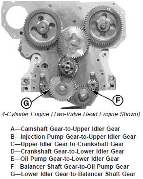
Balancer Shaft-to-Oil Pump
(4-Cyl. Only) (F)—Backlash 0.06—0.65 mm (0.0025—0.0255 in.)
Lower Idler-to-Balancer Shaft
(4-Cyl. Only) (G)—Backlash 0.07—0.65 mm(0.0027—0.0255 in.)
Camshaft-to-Auxiliary Drive (NotShown)—Backlash 0.05—0.68 mm(0.0021—0.0266 in.)
拆下凸轮轴
NOTE: It is not necessary to remove cylinder head fromengine for camshaft removal. If push rods arebent or show excessive scuffing, it may benecessary to remove cylinder head for inspectionof block, head and camshaft followers. (SeeREMOVE CYLINDER HEAD in Group 020 or021.)
New service camshafts have fixed gears.Camshaft and gear are replaced as an assembly.
1. Drain engine oil and coolant, if not previously done.
2. Measure valve lift. (See MEASURE VALVE LIFT,earlier in this group).
3. Remove rocker arm assembly and push rods. (SeeREMOVE CYLINDER HEAD in Group 020.)
4. Remove timing gear cover. (See REMOVE TIMINGGEAR COVER, earlier in this group.)
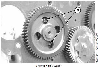
5. Remove cap screws (A) and camshaft activated fuelsupply pump. See REMOVE FUEL SUPPLY PUMP inSection 02, Group 090 of CTM207 (Mechanical FuelSystems), REMOVE FUEL SUPPLY PUMP in Section02, Group 090 of CTM331 (Level 12 Electronic FuelSystems with Stanadyne DE10 Pump) or REMOVEMECHANICAL FUEL TRANSFER PUMP in Section 02,Group 090 of CTM220 (Level 11 Electronic FuelSystems with Denso High Pressure Common Rail).
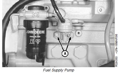
6. Rotate engine gear train until cap screws (A) can beremoved.
A—Cap Screws
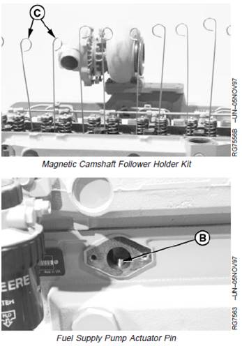
IMPORTANT: Engine MUST remain in a positionwhere camshaft followers rest againstcylinder head or are held in up positionwith magnetic holders so that followersdo not fall into engine crankcase. Ifcamshaft followers fall into crankcase,cylinder head removal is required.
NOTE: D15001NU Magnetic Follower Holder Kit (C) mayalso be used to hold camshaft followers awayfrom lobes.
7. Revolve engine on repair stand to an angle wherecamshaft followers and fuel supply pump actuator pin(B) falls away from camshaft lobes.
IMPORTANT: DO NOT allow camshaft lobes to drag inbushing or honed bores.
8. Carefully pull camshaft straight up, out of cylinderblock.
NOTE: Rotate camshaft carefully to aid in removing.
B—Pump Actuator Pin
C—Magnetic Follower Holder Kit
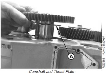
9. Remove thrust plate (A) from slot behind camshaftgear.
A—Thrust Plate
John Deere约翰迪尔强鹿柴油机凸轮轴的检查
1. Clean camshaft in solvent. Dry with compressed air.
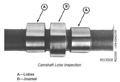
2. Inspect all camshaft lobes (A) and journals (B) for wear or damage. Replace camshaft as necessary.
3. Inspect camshaft for broken, cracked or excessively worn drive gear. Replace camshaft as necessary.
IMPORTANT: New camshaft followers can be used with old camshaft. DO NOT reuse old camshaft followers with a new camshaft.
NOTE: Very light score marks are acceptable if valve lift is within specification. If pitting or galling exists, replace camshaft. (See MEASURE VALVE LIFT earlier in this group.)
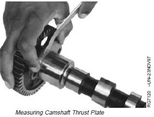
凸轮轴止推板间隙的测量
Clean camshaft thrust plate and check clearance using a feeler gauge. Replace parts as necessary.
Specification
Camshaft Thrust Plate—Clearance 0.08—0.23 mm (0.003—0.009 in.)
NOTE: Thrust plate clearance determines camshaft endplay.
Check thrust plate thickness.
Specification
Camshaft Thrust Plate—Thickness............................................. 3.96—4.01 mm (0.156—0.158 in.)
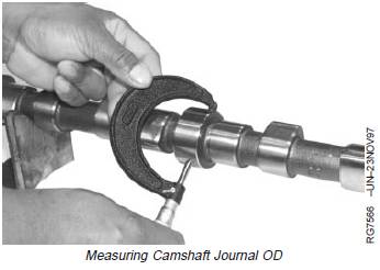
凸轮轴衬套的检查和测量与标准值参数
All engine camshafts have a (replaceable) bushing installed in No. 1 (front) camshaft bore.
1. Measure camshaft journals. If a camshaft journal is damaged or does not meet specification, install a new camshaft.
2. Measure camshaft bushing ID and remaining bores in cylinder block. If camshaft bore is damaged or is not within specification, have a qualified machine shop install new bushings.
If No. 1 camshaft bushing ID does not meet specifications, replace camshaft bushing. (See REMOVE AND INSTALL CAMSHAFT BUSHING earlier in this group.)
Camshaft Bearing Bores and Journals—Specification
Camshaft Journal—OD 55.872—55.898 mm (2.1997—2.2007 in.)
Camshaft Bore, Front No. 1 in
Block (Without Bushing)—ID 59.961—59.987 mm (2.3607—2.3617 in.)
Camshaft Bore, Front No. 1 in
Block (With Bushing)—ID 55.961—55.987 mm (2.2031—2.2042 in.)
Camshaft Bore, All Except No.
1—ID 55.986—56.012 mm (2.2042—2.2052 in.)
Camshaft Journal-to-Bushing, No.
1 Bore (With Bushing)—Oil
Clearance 0.063—0.115 mm (0.0025—0.0045 in.)
Camshaft Journal-to-Bushing, All
Except No. 1 Bore—Oil Clearance 0.088—0.140 mm (0.0035—0.0055 in.)
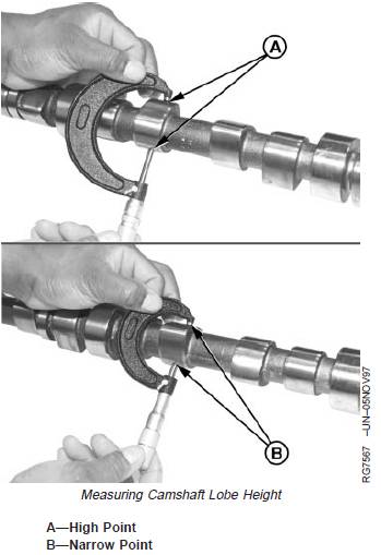
Measure Camshaft Lobe Height
1. Measure each camshaft lobe at highest point (A) and at narrowest point (B). The difference between is camshaft lobe height. If height is not within specification on any lobe, install a new camshaft.
Specification
Camshaft Intake Lobe (Two-ValveHead Engines)—Height....................... 7.05—7.31 mm (0.278—0.288 in.)
Camshaft Intake Lobe
(Four-Valve Head Engines)—Height .................................................. 5.88—6.14 mm (0.231—0.242 in.)
Camshaft Exhaust Lobe
(Two-Valve Head Engines)—Height .................................................. 6.89—7.15 mm (0.271—0.281 in.)
Camshaft Exhaust Lobe
(Four-Valve Head Engines)—Height .................................................. 5.84—6.10 mm (0.230—0.240 in.)
2. Measure fuel supply pump camshaft lobe diameter. Ifdiameter is not within specification or lobe surface isgrooved, install a new camshaft.
Specification
Fuel Supply Pump Camshaft
Lobe (Early)—Diameter....................... 41.15—41.41 mm (1.62—1.63 in.)
Fuel Supply Pump Camshaft
Lobe (Late)—Diameter ........................ 42.67—42.93 mm (1.68—1.69 in.)
凸轮轴齿轮的检查
IMPORTANT: Camshaft must be replaced if droppedor damaged. Camshaft gear and shaftkey are no longer available as serviceparts. If gear is damaged, replacecamshaft and gear as an assembly.
1. Clean camshaft and gear in solvent. Dry withcompressed air.
2. Inspect camshaft gear for nicks and scratches.Replace camshaft and gear assembly if damage isfound.
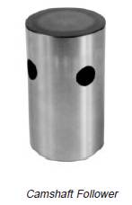
Inspect Camshaft Followers
NOTE: Cylinder head must be removed before camshaft followers can be removed from engine. (See REMOVE CYLINDER HEAD in Group 020 or 021.)
1. Inspect followers for uneven wear or damage. Also inspect corresponding camshaft lobe for wear or damage. Replace as necessary.
2. Measure follower OD and follower bore ID in cylinder block.
Specification
Camshaft Follower—OD 31.61—31.64 mm (1.245—1.246 in.)
Camshaft Follower Bore in
Block—ID 31.70—31.75 mm (1.248—1.250 in.)
Camshaft Follower-to-Bore—Clearance ............................................ 0.06—0.13 mm (0.002—0.005 in.)
Replace camshaft followers that are not within specification. Replace cylinder block if any one camshaft follower bore is not within specification.