 English
 Espaol
 Franais
 阿拉伯
阿拉伯 中文
中文 Deutsch
 Italiano
 Português
 日本
日本 韩国
韩国 български
 hrvatski
 esky
esky Dansk
Dansk Nederlands
 suomi
suomi Ελληνικ
 印度
印度 norsk
norsk Polski
 Roman
Roman русский
 Svenska
John Deere强鹿柴油机曲轴与曲轴瓦的安装方法供应商,John Deere强鹿柴油机曲轴与曲轴瓦的安装方法技术价格规格咨询服务,John Deere强鹿柴油机曲轴与曲轴瓦的安装方法零配件供应,John Deere强鹿柴油机曲轴与曲轴瓦的安装方法售后服务中心,John Deere强鹿柴油机曲轴与曲轴瓦的安装方法,John Deere强鹿柴油机曲轴与曲轴瓦的安装方法详细的技术参数,

产品中心
John Deere强鹿柴油机曲轴与曲轴瓦的安装方法
详细描述
John Deere约翰迪尔强鹿柴油机曲轴与曲轴瓦的安装方法
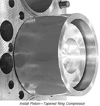
IMPORTANT: Be careful so crankshaft journals and liner walls are not damaged by connecting rod when installing piston and rod in liner.
1. Coat pistons, liners and inside of piston ring compressor with clean engine oil.
2. Carefully place JDE84 Piston Ring Compressor withpiston and rod over liner so the word “FRONT” on sideof rod and on the side of piston faces toward the frontof the engine.
NOTE: Be sure the word “FRONT” on connecting rodfaces toward the front of the engine.If arrow indicating “FRONT” is not visible on top ofpistons, install piston and rod so combustion bowlin piston is offset toward fuel injection pump sideof engine, and the long side of the connecting rodis toward camshaft side of engine.
3. With piston centered in ring compressor and ringsstaggered correctly, push piston down until top ring isinto liner.
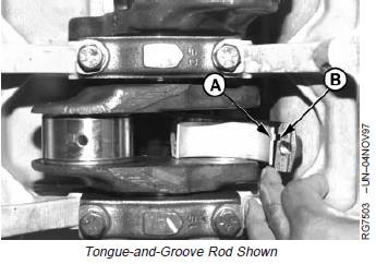
4. Install bearing insert in connecting rod with tang (A) ingroove (B).
5. Apply clean engine oil on insert and crankshaft journal.Carefully pull connecting rod and insert againstcrankshaft journal.
A—Tang
B—Groove
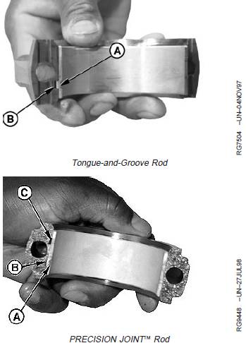
NOTE: Due to the manufacturing process, thePRECISION JOINTä rod and cap both have twogrooves, while the bearing insert has a singletang. Only the one groove in the rod and cap isused for the bearing tang.
6. Install bearing insert in connecting rod cap with tang(A) in groove (B).
IMPORTANT: On PRECISION JOINTä connectingrods, make sure cap is properly alignedon rod with edges flush andinterlocking surfaces sealed tightly.
7. Apply clean engine oil to bearing insert. Install cap onconnecting rod with tangs to same side.
A—Tang
B—Groove
C—Extra Groove (Not Used)
IMPORTANT: NEVER use connecting rod cap screwsmore than once for final engineassembly. Once rod cap screws havebeen tightened to final torque-turnspecification, they must not be reusedfor another final assembly.
Cap screws for PRECISION JOINTä rodand cap are 3 mm shorter thantongue-and-groove cap screws. DO NOT
mix hardware.
Two types of connecting rods and capsmay be used within the same engine,however the correct cap screws mustbe used for each type of connectingrod.
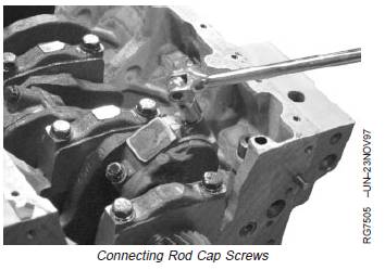
8. Dip NEW connecting rod cap screws in clean oil andinstall.
9. Tighten cap screws alternately to initial torquespecification.
Specification
Connecting Rod Cap Screws—Initial Torque.................................................................... 58 N•m (43 lb-ft)
10. Then, torque-turn all cap screws to 90—100 degrees.(See TORQUE-TURN CONNECTING ROD CAPSCREWS next in this group.)
John Deere约翰迪尔强鹿柴油机活塞突出量的测量与标准值参数
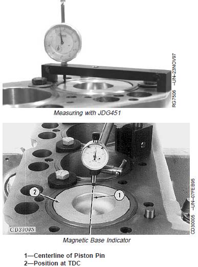
1. Press down on top of piston to remove oil clearances before measuring piston protrusion.
NOTE: If JDG451 or KJD10123 are not available, a dial indicator with magnetic base can be used to measure piston protrusion.

2. Use JDG451 or KJD10123 Height Gauge (or use a magnetic base dial indicator) to measure piston protrusion. Place gauge on top of cylinder block so dial indicator can be set to “zero” with top of block.
3. Position gauge across piston as close to centerline of piston pin as possible. While pressing gauge downward, rotate crankshaft until piston is at TDCposition. Measure piston height at several positions around the outermost diameter of piston. Piston height must be checked at outermost diameter of piston.
4. Piston protrusion must be within specifications to prevent piston-to-exhaust valve contact.
5. Measure piston protrusion and compare to the following specifications. If protrusion does not meet specifications, check dimensions of piston, connecting rod, cylinder block, crankshaft, and bearings to determine the cause.
Piston Protrusion—Specification
4-Cyl. Standard Duty
Codes 4801, 4803, 4809.
6-Cyl. Standard Duty
Codes 4805, 4807.—Piston
Protrusion 0.08—0.31 mm (0.003—0.012 in.)
4-Cyl. Heavy Duty
Code 4804.
6-Cyl. Heavy Duty
Codes 4808, 4810 and All
Four-Valve Head Engines.—Piston Protrusion 0.08—0.25 mm (0.003—0.010 in.)
Complete Final Assembly
1. Install oil pump outlet tube O-ring in cylinder block.Install oil pump and outlet tube. (See INSTALLENGINE OIL PUMP in Group 060.)
2. Install balancer shaft bushings (4-cylinder engines).(See REMOVE AND INSTALL BALANCER SHAFTBUSHINGS in Group 050.)
3. Install camshaft bushings. (See REMOVE ANDINSTALL CAMSHAFT BUSHINGS in Group 050.)
4. Install oil bypass valve (in front of block) and frontplate. (See INSTALL CYLINDER BLOCK FRONTPLATE in Group 050.)
5. Install balancer shafts (if equipped). (See INSTALLAND TIME BALANCER SHAFTS in Group 050.)
6. Install camshaft and timing gears. (See INSTALLCAMSHAFT in Group 050.)
7. If equipped with cartridge type oil pressurregulating valve, install valve. (See REMOVE AND
INSTALL OIL PRESSURE REGULATING VALVE inGroup 060.)
8. Install timing gear cover. (See INSTALL TIMINGGEAR COVER in Group 050.)
9. If equipped with spring, plunger and seat type oilpressure regulating valve, install valve assembly.(See REMOVE AND INSTALL OIL PRESSUREREGULATING VALVE in Group 060.)
10. Install oil pan. (See INSTALL OIL PAN in Group060.)
11. Install crankshaft pulley. (See INSTALL PULLEYOR VIBRATION DAMPER PULLEY in Group 040.)
12. Install camshaft followers. (See INSPECT,MEASURE AND ASSEMBLE CAMSHAFTFOLLOWERS in Group 050.)
13. Install cylinder head with new gasket. (SeeINSTALL CYLINDER HEAD in Group 020 for twovalve head or INSTALL CYLINDER HEAD inGroup 021 for four valve head.)
14. Fill engine with clean oil and proper coolant.
15. Perform engine break-in. (See PERFORMENGINE BREAK-IN in Group 010.)