English
 Espaol
 Franais
 阿拉伯
阿拉伯 中文
中文 Deutsch
 Italiano
 Português
 日本
日本 韩国
韩国 български
 hrvatski
 esky
esky Dansk
Dansk Nederlands
 suomi
suomi Ελληνικ
 印度
印度 norsk
norsk Polski
 Roman
Roman русский
 Svenska
我们是***的John Deere约翰迪尔强鹿柴油发动机缸套突出量的测量方法与标准值参数供应服务商.我们可提供John Deere约翰迪尔强鹿柴油发动机缸套突出量的测量方法与标准值参数销售维修保养零配件服务.John Deere约翰迪尔强鹿柴油发动机缸套突出量的测量方法与标准值参数想要更多的类型,请现在联系湖南英珀威机械有限公司!

产品中心
John Deere约翰迪尔强鹿柴油发动机缸套突出量的测量方法与标准值参数
详细描述
John Deere约翰迪尔强鹿柴油发动机缸套突出量的测量方法与标准值参数
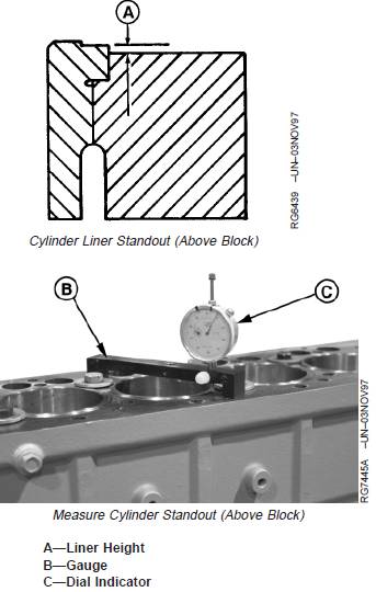
1. Secure liners using cap screws and flat washers. Flatwashers should be at least 3.18 mm (1/8 in.) thick.Tighten cap screws to 68 N•m (50 lb-ft).
2. Using JDG451 or KJD10123 Gauge (B) and D17526CIor D17527CI Dial Indicator (C), measure liner height
(A) at 1, 5, 7, and 11 o’clock positions as viewed fromflywheel end of engine. Record all measurements bycylinder number.
Specification
Cylinder Liner—Height aboveBlock 0.030—0.100 mm(0.001—0.004 in.)
Maximum Permissible HeightDifference at Nearest Point ofTwo Adjacent Liners, or Within a
Single Liner................................................................. 0.05 mm (0.002 in.)
IMPORTANT: ONE LINER SHIM ONLY may beinstalled under each liner flange.
3. Remove and shim, or replace, any liner that does notmeet height specifications. (See REMOVE CYLINDERLINERS in Group 030.)
NOTE: Two sizes of shims are available: 0.05 mm (0.002in.) and 0.10 mm (0.004 in.).
气缸盖的安装
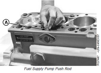
1. Dip fuel supply pump push rod (A) (if equipped) inclean engine oil and carefully install in cylinder blockbefore installing cylinder head.
A—Fuel Supply Pump Push Rod
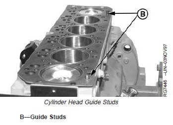
IMPORTANT: The O-ring seals in head gasket can bedamaged if head is repositioned whileresting on engine block. Use guidestuds to position cylinder head onblock.
2. Install two guide studs (B) in cylinder block at locatingholes.
IMPORTANT: ALWAYS thoroughly inspect cylinderhead gasket for possible manufacturingimperfections. Return any gasket thatdoes not pass inspection.
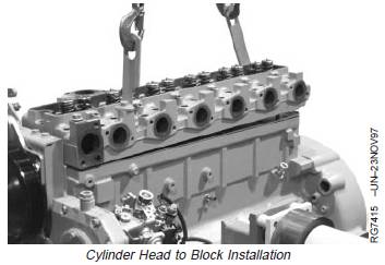
3. Place new head gasket on cylinder block. Do not usesealant; install dry.
4. Position cylinder head over guide studs and lower ontocylinder block.
5. Dip entire cap screw in clean engine oil. Removeexcess oil from screw.
6. Remove guide studs. Install flanged-head cylinderhead cap screws.
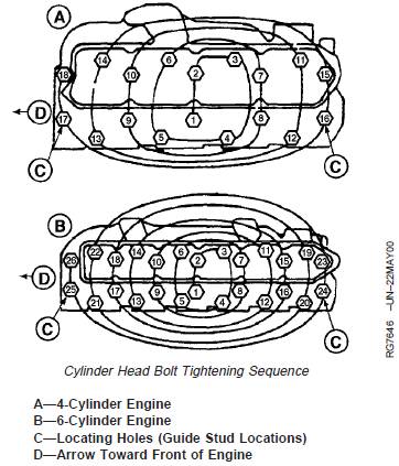
7. Tighten all cap screws to specified torques (insequence shown, beginning with No. 1), followingsteps 1—4 below. Then, torque-turn cap screwsfollowing procedure on next page.
Cylinder Head Cap Screws—Specification
Step 1—Initial—Torque ................................................. 100 N•m (75 lb-ft)
Step 2—Second—Torque ........................................... 150 N•m (110 lb-ft)
Step 3—Verify (After 5Minutes)—Torque........................................................ 150 N•m (110 lb-ft)
Step 4—Final—Torque-Turn Tighten each screw an additional60° ± 10°. (See TORQUE-TURNMETHOD FOR PROPERTORQUE in this group.)
Retorque of cylinder head cap screws after enginebreak-in is not required when using the recommendedtorque procedure along with flanged-head cap screw.