 English
 Espaol
 Franais
 阿拉伯
阿拉伯 中文
中文 Deutsch
 Italiano
 Português
 日本
日本 韩国
韩国 български
 hrvatski
 esky
esky Dansk
Dansk Nederlands
 suomi
suomi Ελληνικ
 印度
印度 norsk
norsk Polski
 Roman
Roman русский
 Svenska
Perkins3012柴油发动机威尔逊P850E柴油发电机配件CV12651燃料过滤器供应商,Perkins3012柴油发动机威尔逊P850E柴油发电机配件CV12651燃料过滤器技术价格规格咨询服务,Perkins3012柴油发动机威尔逊P850E柴油发电机配件CV12651燃料过滤器零配件供应,Perkins3012柴油发动机威尔逊P850E柴油发电机配件CV12651燃料过滤器售后服务中心,Perkins3012柴油发动机威尔逊P850E柴油发电机配件CV12651燃料过滤器,Perkins3012柴油发动机威尔逊P850E柴油发电机配件CV12651燃料过滤器详细的技术参数,

产品中心
Perkins3012柴油发动机威尔逊P850E柴油发电机配件CV12651燃料过滤器
详细描述
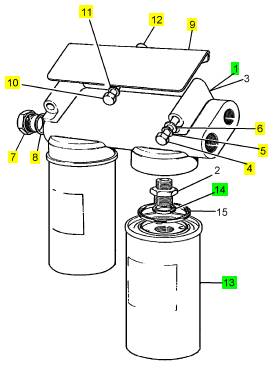
项目 零配件号码 最近的部分号码 描述
1 CV12651 1 燃料过滤器冒口
4 ST43514 3 ST43514 螺拴
5 2134 A008 3 2134 A008 垫圈
6 2131 A008 3 2131 A008 垫圈
7 ST46077 1 ST46077 栓塞
8 ST49852 1 ST49852 垫圈
9 CV5594 1 CV5594 HEATSHIELD
10 ST43506 3 ST43506 螺拴
11 2134 A008 3 2134 A008 垫圈
12 CV7039 3 CV7039 距离块
13 OD19596 2 OD19596 燃料过滤器
14 OD19444 1 OD19444 密封O型圈
项目 零配件号码 最近的部分号码 描述
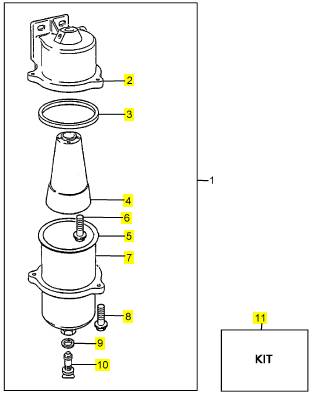
1 OD19525 1 OE52601 燃料过滤器组合
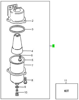
项目 零配件号码 最近的部分号码 描述
2 OD19718 1 OD19718 体
3 OD19723 1 OE52601 圈
4 OD19720 1 OD19720 锥形
5 1 接合
6 OD19724 3 OD19724 螺旋
7 OD19719 1 OE52601 手提浇斗
8 OD19724 3 OD19724 螺旋
9 1 密封
10 OD19722 1 26560134 栓塞
11 KRP1244 1 KRP1244 修理装备 - 燃料的过滤器
|
Each air filter is fitted with an indicator (A) which gives
a visual warning when the filter needs a service.
When the red warning indicator is seen through the
clear panel after the engine has stopped, the air filter
element must be renewed.
After a clean element has been fitted, press the reset
button on the res triction indicator.
filters
The two air filters (B) contain paper elements. These
must not be washed. Renew the paper elements as
follows:
1 Loosen the clamp and remove the end cover (B1).
Remove the wing nut (B2), withdraw and discard the
filter element (B3).
2 Clean, thoroughly, the inside of the casing of the air
filter. Fit a new filter element and fit the end cover.
3 Reset the restriction indicator.
Repeat this procedure for the other air filter.
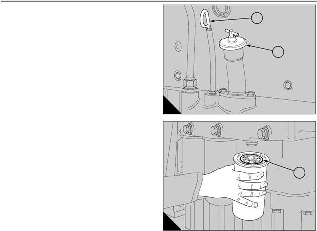
How to drain the primary fuel filter
1 Remove the drain plug from the base of the filter
bowl and allow any water or sediment to drain from
the unit.
2 Fit the drain plug and tighten it securely.
A
3
2
37
1
B
21
19
This document has been printed from SPI². Not for Resale
 4
4
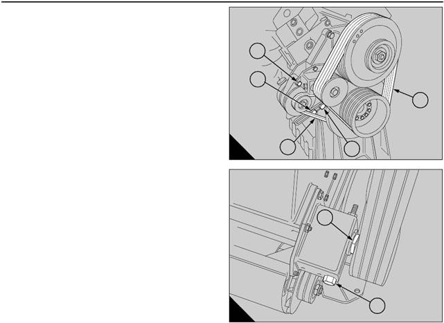
How to check the drive belts
Check all drive belts and renew a belt if it is worn or
damaged. Where more than one belt is used between
two pulley s, all of the belts must be renewed together.
Maximum belt life will be obtained only if the belts are
kept at the correct tensions.
Check the belt tension at the centre of the longest free
length, for ex ample, position (A5) to check the fan
drive belts.
Use a ‘Gates "Krikit" V-belt tension gauge’ or similar
tool to check the tension of the belts.
The correct tension for all belts is 400 to 489 N (90 to
100 lbf). Where more than one belt is used between
two pulleys, check/adjust the tension on the tightest
belt.
Note: When new belts are fitted they must be
checked again after the engine has been run for 15
minutes and, if necessary, adjus ted to the correct
tension.
How to adjust the tension of the fan belts
1 To adjust the tension of the fan belts, loosen the
nuts on the adjustment bolt. Loosen the large loc k nut
(B1) on the belt tensioner and turn the adjustment bolt
(B2) until the correct tension is obtained.
2 Tighten the lock nut and check the tension of the
A
B
1
2
4
1
3
2
5
59
60
belts again.
3 Run the engine for 15 minutes and then check the
belt tension again.
Check the tension of new belts every week for four
weeks and then at the intervals specified in the
service schedule
How to adjust the tension of the alternator belt
1 Loosen the alternator pivot bolt (A1), the
adjustment link bolt (A3) and the adjustment bolt (A2).
Move the alternator to obtain the correct belt tension
and tighten the bolts.
2 Run the engine for 15 minutes and then check the
belt tension again.
Check the tension of new belts every week for four
weeks and then at the intervals specified in the
service schedule.
How to renew the fan belts
1 To renew the fan belts, remove the six bolts whic h
fasten the fan to the pulley and push the fan forward
into the radiator cowl.
2 Release the tension on the belts and remove the
old belts. Ensure that the pulley grooves are free from
grease and dirt. Fit a new set of belts.
3 Fit the fan and tighten the bolts s ecurely. Adjust the
fan belts to the correct tension.
20
How t o renew the alternator belt
1 Remove the fan belts from the crankshaft pulley as
given on this page.
2 Loosen the adjustment bolts to release the tension
on the alternator belt and remove the old belt. Check
that the pulley grooves are clean and fit a new belt.
Adjust the belt to the correct tension. Fit the fan belts
as given on this page.
This document has been printed from SPI². Not for Resale
 4
4
|
Drain some coolant from the cooling sy stem after the
engine has been stopped and before the formation of
sediment. Proceed as follows:
1 For mixtures which contain inhibited ethylene
glycol:
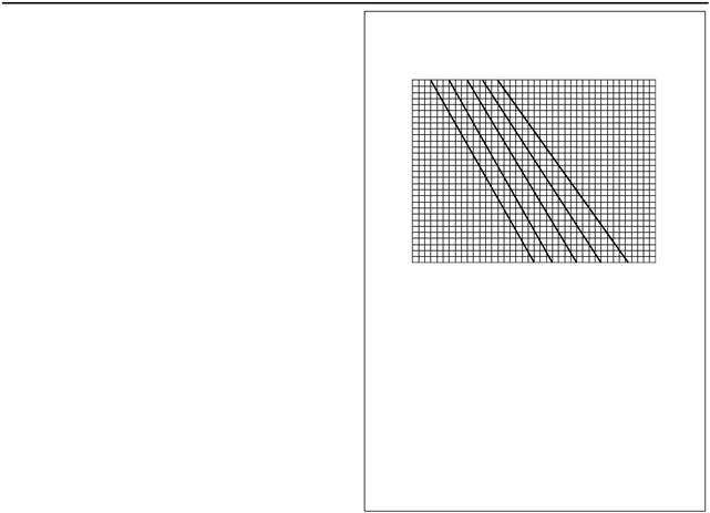
(a) Put a hydrometer, and a reliable thermometer,
into the antifreeze mixture and check the readings
on both instruments.
(b) Compare the readings obtained with the chart
and adjust the strength of the mixture as
necessary.
C
60
50
40
30
20
10
0
40
45
50 55 60
A
140
122
104
86
68
50
D
2 For mixtures which contain inhibited propylene
glycol:
(a) Open the cover of the refractometer, check that
the clear panel is clean and use a small syringe to
apply three or four drops of the coolant mix ture to
1.04
1.05
1.06
1.07
B
1.08
1.09
1.10
1.11
the clear panel.
(b) Spread the coolant over the full area of the
clear panel and close the cover. Hold the
refractometer horizontally with the clear panel at
the top and inspect the sample through the viewer.
(c) Compare the reading with the chart in the
instructions; adjust the strength of the mixture as
necessary.
Specific gravity chart
A = Percentage anti-freeze by volume
B = Specific gravity
C = Mixture temperature in Centigrade
D = Mixture temperature in Fahrenheit
Caution: The clear panel must be cleaned
thoroughly before use. Some of the fluid which was
tested earlier can remain on the clear panel and this
will affect the reading of the sample.
Protection against frost is as follows:
Antifreeze/water Protection down to
(% by volume) (°C)
50/50 -35
60/40 -40
How to check the pH value of the coolant
The pH value of the coolant must not be less than pH7
or more than pH9.5. The pH value can be found by
the use of a pH meter or test papers, which are
available from pharmaceutical manufacturers.
If these limits are exceeded the pH value may be
adjusted by the addition of a corrosion inhibitor to the
same specification as that already in use. If this is not
possible, the system must be drained, flushed and
filled with new coolant.
21
This document has been printed from SPI². Not for Resale
 4
4
How to renew the engine lubricating oil
1 Operate the engine until it is warm.
2 Stop the engine, remove the sump drain plug and
drain the lubricating oil from the sump. Fit the drain
plug, complete with a new sealing washer, and tighten
the plug to a torque of 47 Nm (35 lbf ft). If the plug is
fitted to a steel insert, tighten the plug to a torque of
115 Nm (85 lbf ft).
3 Renew the three oil filter canisters as given below.
4 Clean the area around the oil filler cap (A2) and
remove the c ap. Fill the sump to the H mark on the
dipstick (A1) with clean new lubricating oil of an
approved grade as given on page 32. Do NOT overfill.
5 Operate the engine and check for leakage from the
filter canisters. When the engine has cooled, check
the oil level on the dips tick and put more oil into the
sump, if necessary.
How to renew the canisters of the oil filter
Three screw-on type canisters are fitted to the filter
head which is integral with the bottom of the engine oil
cooler.
1 Put a tray under the canisters to retain the spilt
lubricating oil. Use a s trap wrench to remove each
canister.
A
B
1
2
1
61
64
|
to the new canisters and clean the contact faces of
the filter head.
3 Lubricate the top of each canister seal with clean
engine lubric ating oil and fill each canister with the
approved grade of lubricating oil.
4 Fit the new canisters to their adaptors and tighten
each canister until its sealing ring is jus t in contact
with the face of the filter head. Continue to tighten
4
overtighten.
22
This document has been printed from SPI². Not for Resale
 4
4
|
|
1 Remove the three bolts (A1) and remove the filter
bowl (A2).
2 Clean all of the components with paraffin and dry
them with a compressed air jet.
3 Fit the bowl to the filter head, together with a new
sealing ring. Align the clamp ring (A3) and fasten it
with the three bolts.
Early engines can be fitted with filters that have
elements which can be cleaned. These elements
should be removed, cleaned with fuel oil and dried
with a compressed air jet.
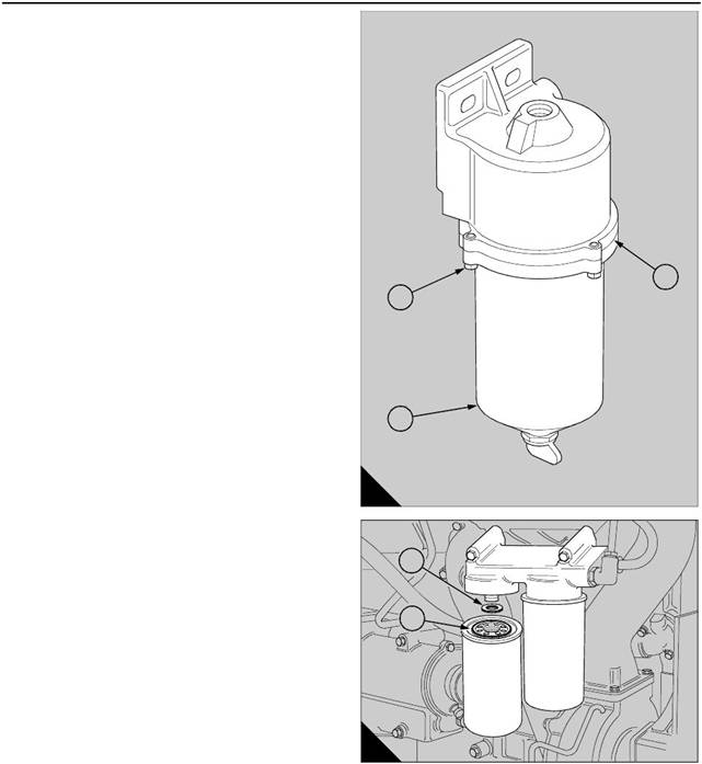
filter
The main fuel filter is at the rear of the engine on the
‘B’ bank side and has two canisters. Both canisters
must be renewed at the same time.
1 Clean the area around the filter and remove the fuel
filter canisters. If necessary, use a strap wrench.
Discard the canisters.
2 Check that the sealing ring (B1) is fitted correctly to
each new canister and clean the contact faces of the
filter head.
3 Lubricate the top of the canister seal (B1) with clean
fuel oil and renew the sealing ring (B2) on the adaptor.
4 Fit the new canisters to their threaded adaptors and
tighten each canister until the sealing ring just comes
into contact with the filter head. Continue to tighten
4
overtighten.
After the fuel filter canisters have been renewed,
eliminate air from the low pressure fuel system as
given on page 27.
A
1
2
2
1
3
65
B
66
23
This document has been printed from SPI². Not for Resale
 4
4
|
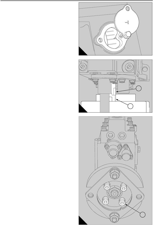
If it becomes necessary to check and adjust the timing
of the fuel injection pump, the procedure which
follows is recommended:
1 Ensure that the stop control is in the ‘STOP’
position.
2 Remov e the high-pressure fuel pipes and the
rocker cover from the cylinder head for A4, A5 and A6
cylinders.
3 Remov e the cover from the flywheel housing as
shown (A).
4 Turn the crankshaft by hand, in the normal direction
of rotation, until the relevant number for injection
timing (s ee the engine data plate) aligns with the
timing pointer at the same time as the valves of A6
cylinder are closed, ie. ‘A6’ piston at TDC on its
compression stroke.
5 Check that the timing mark (B1), on the hub of the
fuel injection pump, aligns with the pointer (B2).
6 If the timing mark (B1) does not align with the
pointer, check that the fuel pump drive shaft and the
coupling are secure and are not damaged, then
proceed as follows :
7 Set the timing position as in paragraph 4 above,
and loosen the four cap screws (C1), or for later
engines s pecial bolts, on the injection pump
adjustable coupling.
8 Turn the hub in the normal direction of rotation by
hand, to just past the timing position. Then turn the
hub back until the timing mark and pointer align;
For earlier engines tighten the four cap s crews
(C1) to 69 Nm (51 lbf ft). For later engines tighten
the four special bolts to 46 Nm (34 lbf ft).
9 Turn the engine in reverse direction for a quarter of
a turn (90°) and then forward, in the normal direction
of rotation, until the flywheel timing pointer is again
aligned with the correct timing point (stamped on the
engine data plate). Check that the timing marks of the
fuel injection pump are correctly aligned.
A
B
1
2
67
68
C
1
69
24
This document has been printed from SPI². Not for Resale
 4
4
Fuel injector fault
A fuel injector fault c an cause an engine misfire.
In order to find which injector is defective, operate the
engine at a fast idle speed. Loosen and tighten the
union nut of the high-pressure fuel pipe at each
injector. When the union nut of the defective injector
is loosened, it has little or no effect on the engine
speed.
Warning! Ensure that the fuel does not spray onto
your skin.
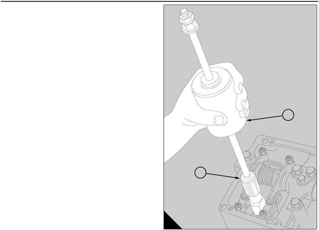
How to remove the fuel injectors
1 Disconnect and remove the high-pressure pipes
and the spill pipes. For early engines, remove the
relevant rocker box cover. Release the connection for
the leak-off fuel from the fuel injector and remove it
through the wall of the rocker box. For later engines,
remove the relevant pedestal rocker cover.
2 Release the relevant clamp and withdraw the fuel
injector. To remove a tight fuel injector, use the Slide
Hammer, 21825 849 (A1) and the relevant Adaptor
(A2): 21825 854 for M18 threads or 21825 860 for
M14 threads.
Caution: Ensure that the copper fuel injector sleeve
is not loosened in the cylinder head during the use of
A
2
1
93
the slide hammer.
How to correct the fuel injector sleeves
To improve the condition of the injector sleeves, us e
the Reamer/facer tool for the injector sleeve. Grease
must be applied to both of the cutters before use, to
retain carbon and metal particles. Do not remove
more metal than is absolutely necessary to correct the
seat face. The max imum permissible depth of the
seat face, measured from the top face of the cylinder
head, is 104,25 mm (4.104 in).
Note: The Reamer/facer tool is assembled from
these tools: 21825 765, 21825 767 and 21825 768.
How to fit the fuel injectors
1 Check that the new injector is fitted with a new ‘O’
ring seal in the machined groove near to the top of the
stem and check that the sleeve for each fuel injector
is c lean.
2 If relevant, remove the connection for the leak-off
fuel from each fuel injector and fit carefully each fuel
injector into its sleeve, with the threaded hole for the
leak-off fuel toward the outer wall of the rocker box.
DO NOT use a sealing washer between the injector
and the seating face of the injector sleeve.
3 Fit the assembly of the metal cup and rubber seal
against the head of each connection for leak-off fuel
and fit a new copper washer onto the thread. For
early engines, insert each connection through the
openings in the outer walls of the rocker boxes and fit
the connection into its fuel injector, finger-tight.
4 Fit the clamps to the relevant fuel injectors,
complete with a spherical washer for each clamp. Fit
the cap screws through the washers and the clamps
and tighten them to 60 Nm (44 lbf ft). For early
engines, when all the cap screws of the clamps are
tight, tighten the connections for leak-off fuel to 27 Nm
(20 lbf ft).
5 Check that the joint face of each rocker box is
c lean. Fit a new joint for each rocker box cover and
align correctly the bolt holes.
Continued
25
This document has been printed from SPI². Not for Resale
 4
4
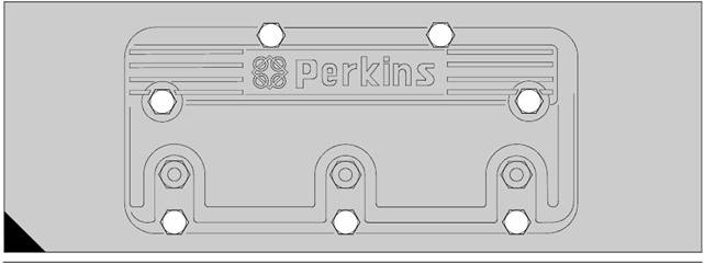
6 Fit c arefully each roc ker box cover and fit the
eight bolts , complete with plain and spring was hers.
Tighten the bolts to 27 Nm (20 lbf ft). For later
engines, fit a new ‘O’ ring around the groove near
the top of each fuel injector. Fit the pedes tal roc ker
cover and tighten lightly all of the bolts . Tighten
ev enly all of the bolts, in the s equence shown (A),
to a torque of 11 Nm (8 lbf ft).
7 For all engines, fit new copper sealing washer to
the connections for leak-off fuel and fit the pipes
between the fuel injectors and the connection block
for the leak-off fuel. Tighten securely each banjo bolt
connection and each union nut.
8 Fit each high-pressure fuel pipe between its
delivery valve and its fuel injector. Tighten by hand
each nut. DO NOT bend a pipe to make it fit between
its connections. Tighten securely each nut to 45 Nm
(33 lbf ft).
Note: The identification of each high-pressure fuel
pipe is made by the cylinder number which is stamped
on the union nut which is fitted to the fuel injector.
9 Fit new rubber dampers around each high-pressure
fuel pipe. Fit the shrouds over the rubber dampers
and retain securely each s hroud to its induction
manifold with bolts and spring washers.
10 Eliminate air from the high-pressure fuel system
as given on page 27.
11 Run the engine and check for leaks.
4
6
1
2
A
7
3
5
70
26
This document has been printed from SPI². Not for Resale
 4
4
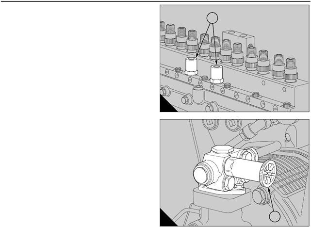
How to eliminate air from the fuel system
If air enters the fuel system, the injection pump
pressure may become insufficient to operate the
injector valves and the engine may stop, misfire or fail
to start.
To eliminate air from the system, use the relevant
procedure which follows:
Low pressure system
1 Loosen the low pressure relief valves (A1) on the
fuel injection pump and operate the priming plunger
(B1) of the fuel lift pump. When fuel, free from air,
flows from the relief valves, tighten the unions.
2 Clean away fuel that has been spilled.
High pressure system
Air in the high pressure system must be released at
the injectors.
1 Mov e the s top control to the RUN position and
operate the starter motor.
2 Loosen the nut of the high-pressure fuel pipe at one
of the injectors. When fuel, free from air, is released,
tighten the nut to a torque of 45 Nm (33 lbf ft). DO
NOT OVERTIGHTEN.
Warning! Ensure that fuel does not spray onto your
skin.
A
B
1
1
71
72
3 Repeat the procedure for the remainder of the fuel
injectors.
4 If the engine starts during this operation but runs
erratically, continue to eliminate air from each injector
until the high pressure system is free from air or until
the engine runs correctly.
5 Return the stop control to the STOP position.
6 Clean away any fuel that has been spilled.