 English
 Espaol
 Franais
 阿拉伯
阿拉伯 中文
中文 Deutsch
 Italiano
 Português
 日本
日本 韩国
韩国 български
 hrvatski
 esky
esky Dansk
Dansk Nederlands
 suomi
suomi Ελληνικ
 印度
印度 norsk
norsk Polski
 Roman
Roman русский
 Svenska
Perkins3012柴油发动机威尔逊P850E柴油发电机配件启动马达供应商,Perkins3012柴油发动机威尔逊P850E柴油发电机配件启动马达技术价格规格咨询服务,Perkins3012柴油发动机威尔逊P850E柴油发电机配件启动马达零配件供应,Perkins3012柴油发动机威尔逊P850E柴油发电机配件启动马达售后服务中心,Perkins3012柴油发动机威尔逊P850E柴油发电机配件启动马达,Perkins3012柴油发动机威尔逊P850E柴油发电机配件启动马达详细的技术参数,

产品中心
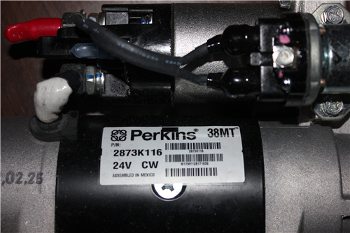
Perkins3012柴油发动机威尔逊P850E柴油发电机配件启动马达
详细描述
项目 零配件号码 最近的部分号码 描述
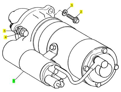
1 CV5296 1 CV65430 启动马达
(1) CV5296R 1 CV65430R 启动马达 -交换
2 ST44500 2 ST44500 固定螺钉
3 ST43164 2 ST43164 垫圈
4 ST44500 1 ST44500 固定螺钉
5 ST43164 1 ST43164 垫圈
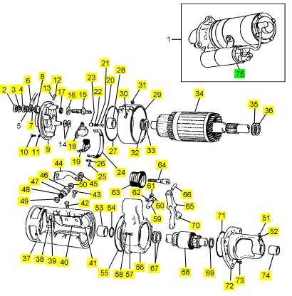
项目 零配件号码 最近的部分号码 描述
2 OD17688 1 OD17688 锁紧螺母
3 OD15391 1 OD15391 垫圈
4 OD15390 1 OD15390 螺帽
5 OD15400 1 OD15400 垫圈
6 CV3022 1 CV3022 铅
7 OD19782 1 OD19782 垫圈
8 OD15396 2 OD15396 衬套
9 OD17266 1 OD17266 壳
10 OD15401 4 OD15401 固定螺钉
11 OD15402 4 OD15402 垫圈
12 OD15392 1 OD15392 栓塞
13 OD16762 1 OD16762 心
14 OD15404 12 OD15404 垫圈
15 OD17267 1 OD17267 连接
16 OD15400 1 OD15400 垫圈
17 OD15397 1 OD15397 CIRCLIP
18 OD17268 4 OD17268 夹持工具
19 OD15415 8 OD15415 刷
20 OD15408 4 OD15408 螺旋
21 OD15407 4 OD15407 垫圈
22 OD15406 4 OD15406 垫圈
23 OD15405 4 OD15405 衬套
24 CV4828 1 CV4828 连接
25 OD15412 8 OD15412 螺旋
26 OD15411 4 OD15411 板
27 OD15417 1 OD15417I 密封O型圈
28 OD15399 1 OD15399 衬套
29 OD17269 1 OD17269 带
30 OD17270 2 OD17270 螺旋
31 OD15419 2 OD15419 螺帽
32 OD15410 1 OD15410 垫圈
33 OD15409 1 OD15409 垫圈
34 OD21480 1 OD21480 电枢
35 OD15423 1 OD15423 垫圈
36 OD15424 1 OD21474 垫圈
37 CV3024 1 CV3024 箱组合
38 CV3027 1 CV3027 螺旋
39 OD20701 1 OD20701 绝缘体
40 CV3026 4 CV3026 磁石的板
41 CV3025 1 CV3025 线圈
42 OD16748 8 OD16748 螺旋
43 OD15422 2 OD15422 螺旋
44 CV3021 1 CV3021 连接
45 OD17688 3 OD17688 锁紧螺母
46 CV3030 1 CV3030 垫圈
47 OD20703 1 OD20703 绝缘体
48 OD15397 1 OD15397 CIRCLIP
49 OD20702 1 OD20702 绝缘体
50 OD15390 1 OD15390 螺帽
51 OD15392 1 OD15392 栓塞
52 OD16762 1 OD16762 心
53 OD19783 1 OD19783I 套筒
54 OD16755 1 OD16755 密封O型圈
55 OD15417 1 OD15417I 密封O型圈
56 OD17275 1 OD17275 壳
57 OD16754 5 OD16754 螺旋
58 OD15402 5 OD15402 垫圈
59 OD16753 1 杆
60 OD16752 1 OD16752 密封O型圈
61 OD16751 1 OD16751 螺旋
62 OD17276 1 OD17276 垫圈
63 OD16765 1 OD16765 长靴
64 OD16756 1 OD16756 螺旋
65 CV3031 1 CV3031 杆
66 OD16747 1 OD16747I 轧辊销
67 OD15424 2 OD21474 垫圈
68 OD16758 1 Y97/00032 驾驶
69 CV4838 1 CV4838 止推片
70 CV3032 2 CV3032 臂
71 OD16759 1 OD16759 密封O型圈
72 OD20704 1 OD20704 壳
73 OD16761 6 OD16761 螺旋
74 OD15399 1 OD15399 衬套
75 OD16764 1 OD16764 停机电磁线圈
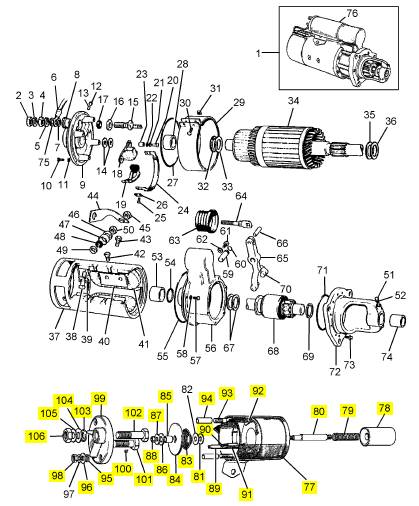
项目 零配件号码 最近的部分号码 描述
77 OD17291 1 OD17291 磁石
78 OD17297 1 OD16764 柱塞
79 OD17282 1 OD17282 弹簧
80 OD18509 1 OD18509 桥
81 OD17252 3 OD17252 垫圈
83 OD17283 1 OD17283 弹簧
84 OD17284 1 OD17284 接触
85 OD17285 1 OD17285 衬套
86 OD17287 1 OD17287 绝缘体
87 OD17185 1 OD17185 垫圈
88 OD17288 1 OD17288 螺帽
89 1 终点
90 1 终点
91 OD17286 1 OD17286 守卫
92 2 终点
93 2 螺旋
94 OD17292 2 OD17292 绝缘体
95 OD17279 2 OD17279 圈
96 OD17252 1 OD17252 垫圈
98 OD17196 2 OD17196 螺帽
99 OD17245 1 OD17245 底座
100 OD17231 1 OD17231 螺旋
101 OD17298 1 OD17298 螺旋
102 OD17299 1 OD17299 螺旋
103 OE52575 4 OE52575 密封O型圈
104 OD17280 2 OD17280 垫圈
105 OD15391 2 OD15391 垫圈
106 OD15390 2 OD15390 螺帽
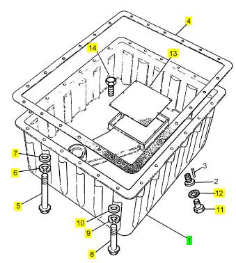
项目 零配件号码 最近的部分号码 描述
1 CV2852/1 1 CV12350 油底壳
4 CV20214 1 CV20214I 密封垫 -油底壳
5 ST43586 4 ST43586 螺拴
6 2134 A010 4 2134 A010 垫圈
7 2131 A010 4 2131 A010 垫圈
8 ST43561 20 ST43561 螺拴
9 2134 A010 20 2134 A010 垫圈
10 2131 A010 20 2131 A010 垫圈
11 CV985 1 CV985 栓塞
12 ST49206 1 ST49206 垫圈
13 CV2874 1 CV2874 过滤器
14 CV1275 7 CV1275 自己的出铁螺旋
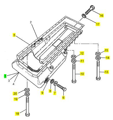
项目 零配件号码 最近的部分号码 描述
1 CV13339 1 CV13339 油底壳承接器
5 CV20213 1 CV20213 密封垫 -油底壳
6 ST43502 2 ST43502 螺拴
7 2134 A008 2 2134 A008 垫圈
8 2131 A008 2 2131 A008 垫圈
9 ST10619 1 ST10619 密封O型圈
10 ST46633 2 ST46633 CAPSCREW
11 2134 A010 2 2134 A010 垫圈
12 2131 A010 2 2131 A010 垫圈
13 ST43561 12 ST43561 螺拴
14 2134 A010 12 2134 A010 垫圈
15 2131 A010 12 2131 A010 垫圈
16 ST46633 5 ST46633 CAPSCREW
17 2134 A010 5 2134 A010 垫圈
18 ST43558 14 ST43558I 螺拴
19 2134 A010 14 2134 A010 垫圈
20 2131 A010 14 2131 A010 垫圈
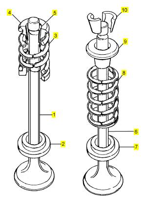
项目 零配件号码 最近的部分号码 描述
1 CV17435 24 CV21058 进气门
2 OE43638 24 OE43638 位子
3 CV11403 24 CV11403 阀弹簧
4 OE43262 24 OE43262 位子
5 OE42571 48 OE42571 阀筒夹
6 CV17434 24 排气阀
7 OE43638 24 OE43638 位子
8 CV11403 24 CV11403 阀弹簧
9 CV18761 24 CV18761 回转的人
10 OE42570 48 OE42570 阀筒夹
Perkins 3000 Series
WORKSHOP MANUAL
3012/CV12
|
|
The contents of this manual are applicable to both CV12 and 3000 Series - 3012 engines. |
Publication TSD 3420, Issue 3
© Perkins Group Limited 2000, all rights reserved.
Published in September 2000 by Technical Public ations.
Perkins Engines Company Limited, Lanc aster Road,
Shrewsbury SY1 3NX, England
1
This document has been printed from SPI². Not for Resale

2
This document has been printed from SPI². Not for Resale
Contents
10 General information
Introduction ... ... ... ... ... ... ... ... ... ... ... ... ... ... ... ... ... ... ... ... ... ... ... ... ... ... ... ... ... . 13
Bank and cylinder bore identification . ... ... ... ... ... ... ... ... ... ... ... ... ... ... ... ... ... ... . 13
Engine identification . ... ... ... ... ... ... ... ... ... ... ... ... ... ... ... ... ... ... ... ... ... ... ... ... ... . 13
General safety precautions .. ... ... ... ... ... ... ... ... ... ... ... ... ... ... ... ... ... ... ... ... ... ... . 14
Safety . ... ... ... ... ... ... ... ... ... ... ... ... ... ... ... ... ... ... ... ... ... ... ... ... ... ... ... ... ... ... ... . 15
Useful information ... ... ... ... ... ... ... ... ... ... ... ... ... ... ... ... ... ... ... ... ... ... ... ... ... ... . 16
Approved lubricants and fluids ... ... ... ... ... ... ... ... ... ... ... ... ... ... ... ... ... ... ... ... ... . 21
11 Specifications
Basic engine data . ... ... ... ... ... ... ... ... ... ... ... ... ... ... ... ... ... ... ... ... ... ... ... ... ... ... . 23
Recommended specific applied torques ... ... ... ... ... ... ... ... ... ... ... ... ... ... ... ... ... . 26
Recommended nominal applied torques ... ... ... ... ... ... ... ... ... ... ... ... ... ... ... ... ... . 28
12 Cyl inder head assembly
General description .. ... ... ... ... ... ... ... ... ... ... ... ... ... ... ... ... ... ... ... ... ... ... ... ... ... . 29
Pedestal rocker cover
12-1 To remove and to fit .. ... ... ... ... ... ... ... ... ... ... ... ... ... ... ... ... ... ... ... ... ... ... ... . 31
Perkins Engines Company Limited
3
This document has been printed from SPI². Not for Resale
Pedestal rocker assembly
12-2 To remove and to fit ... ... ... ... ... ... ... ... ... ... ... ... ... ... ... ... ... ... ... ... ... ... ... ... 32
12-3 To dismantle and to assemble ... ... ... ... ... ... ... ... ... ... ... ... ... ... ... ... ... ... ... ... 33
Rocker box cover
12-4 To remove and to fit ... ... ... ... ... ... ... ... ... ... ... ... ... ... ... ... ... ... ... ... ... ... ... ... 34
Rocker box
12-5 To remove and to fit ... ... ... ... ... ... ... ... ... ... ... ... ... ... ... ... ... ... ... ... ... ... ... ... 34
12-6 To dismantle and to assemble ... ... ... ... ... ... ... ... ... ... ... ... ... ... ... ... ... ... ... ... 35
12-7 To inspect and to correct ... ... ... ... ... ... ... ... ... ... ... ... ... ... ... ... ... ... ... ... ... ... 36
Tappet clearances
12-8 To check and to adjust ... ... ... ... ... ... ... ... ... ... ... ... ... ... ... ... ... ... ... ... ... ... ... 38
Cylinder head assembly
12-9 To remove and to fit ... ... ... ... ... ... ... ... ... ... ... ... ... ... ... ... ... ... ... ... ... ... ... ... 40
12-10 To dis mantle and to assemble . ... ... ... ... ... ... ... ... ... ... ... ... ... ... ... ... ... ... ... 44
12-11 To clean and to inspect the cylinder head ... ... ... ... ... ... ... ... ... ... ... ... ... ... ... 45
12-12 To correct a valve seat ... ... ... ... ... ... ... ... ... ... ... ... ... ... ... ... ... ... ... ... ... ... 46
12-13 To remove a v alve seat insert .. ... ... ... ... ... ... ... ... ... ... ... ... ... ... ... ... ... ... ... 47
12-14 To fit a valve seat insert ... ... ... ... ... ... ... ... ... ... ... ... ... ... ... ... ... ... ... ... ... ... 48
12-15 To ins pect the valve guides . ... ... ... ... ... ... ... ... ... ... ... ... ... ... ... ... ... ... ... ... 49
12-16 To renew a valve guide ... ... ... ... ... ... ... ... ... ... ... ... ... ... ... ... ... ... ... ... ... ... 50
12-17 To ins pect the bridge pieces and guides . ... ... ... ... ... ... ... ... ... ... ... ... ... ... ... 51
12-18 To renew a bridge piece guide ... ... ... ... ... ... ... ... ... ... ... ... ... ... ... ... ... ... ... 51
12-19 To recondition a fuel injector sleeve ... ... ... ... ... ... ... ... ... ... ... ... ... ... ... ... ... 52
12-20 To renew a fuel injector sleeve ... ... ... ... ... ... ... ... ... ... ... ... ... ... ... ... ... ... ... 53
Valves, valve springs and valve rotators
12-21 To remove and to fit . ... ... ... ... ... ... ... ... ... ... ... ... ... ... ... ... ... ... ... ... ... ... ... 57
12-22 To ins pect and to correct . ... ... ... ... ... ... ... ... ... ... ... ... ... ... ... ... ... ... ... ... ... 57
Push rods
12-23 To remove and to fit . ... ... ... ... ... ... ... ... ... ... ... ... ... ... ... ... ... ... ... ... ... ... ... 58
12-24 To inspect ... ... ... ... ... ... ... ... ... ... ... ... ... ... ... ... ... ... ... ... ... ... ... ... ... ... ... 58
Fits and clearances - Cylinder heads, rocker assemblies and valves . ... ... ... ... ... 59
Cylinder heads, rocker assemblies and valves (continued) . ... ... ... ... ... ... ... ... ... 60
4
Perkins Engines Company Limited
This document has been printed from SPI². Not for Resale
13 Pistons and connecti ng rods
General description .. ... ... ... ... ... ... ... ... ... ... ... ... ... ... ... ... ... ... ... ... ... ... ... ... ... . 61
Big end bearings
13-1 To remove and to fit .. ... ... ... ... ... ... ... ... ... ... ... ... ... ... ... ... ... ... ... ... ... ... ... . 63
13-2 To ins pect .. ... ... ... ... ... ... ... ... ... ... ... ... ... ... ... ... ... ... ... ... ... ... ... ... ... ... ... . 64
Piston and connecting rod assembly
13-3 To remove and to fit .. ... ... ... ... ... ... ... ... ... ... ... ... ... ... ... ... ... ... ... ... ... ... ... . 65
13-4 To dismantle and to assemble .. ... ... ... ... ... ... ... ... ... ... ... ... ... ... ... ... ... ... ... . 68
Piston rings
13-5 To remove and to fit .. ... ... ... ... ... ... ... ... ... ... ... ... ... ... ... ... ... ... ... ... ... ... ... . 70
Piston and rings
13-6 To ins pect .. ... ... ... ... ... ... ... ... ... ... ... ... ... ... ... ... ... ... ... ... ... ... ... ... ... ... ... . 71
Connect ing rod
13-7 To ins pect .. ... ... ... ... ... ... ... ... ... ... ... ... ... ... ... ... ... ... ... ... ... ... ... ... ... ... ... . 71
Fits and clearances - Pist ons and connecting rods
Pistons - 4 rings ... ... ... ... ... ... ... ... ... ... ... ... ... ... ... ... ... ... ... ... ... ... ... ... ... ... ... . 72
Piston rings ... ... ... ... ... ... ... ... ... ... ... ... ... ... ... ... ... ... ... ... ... ... ... ... ... ... ... ... ... . 72
Pistons - 3 rings ... ... ... ... ... ... ... ... ... ... ... ... ... ... ... ... ... ... ... ... ... ... ... ... ... ... ... . 74
Piston rings ... ... ... ... ... ... ... ... ... ... ... ... ... ... ... ... ... ... ... ... ... ... ... ... ... ... ... ... ... . 74
Connect ing rods ... ... ... ... ... ... ... ... ... ... ... ... ... ... ... ... ... ... ... ... ... ... ... ... ... ... ... . 76
14 Crankshaft assembly
General description .. ... ... ... ... ... ... ... ... ... ... ... ... ... ... ... ... ... ... ... ... ... ... ... ... ... . 77
Crankshaft pulley, damper and alternator pulley
14-1 To remove and to fit .. ... ... ... ... ... ... ... ... ... ... ... ... ... ... ... ... ... ... ... ... ... ... ... . 78
Front oil seal
14-2 To renew ... ... ... ... ... ... ... ... ... ... ... ... ... ... ... ... ... ... ... ... ... ... ... ... ... ... ... ... . 79
Rear oil seal
14-3 To renew ... ... ... ... ... ... ... ... ... ... ... ... ... ... ... ... ... ... ... ... ... ... ... ... ... ... ... ... . 81
Perkins Engines Company Limited
5
This document has been printed from SPI². Not for Resale
Crankshaft
14-4 To remove and to fit ... ... ... ... ... ... ... ... ... ... ... ... ... ... ... ... ... ... ... ... ... ... ... ... 83
14-5 To dismantle and to assemble ... ... ... ... ... ... ... ... ... ... ... ... ... ... ... ... ... ... ... ... 88
14-6 To clean and inspect .. ... ... ... ... ... ... ... ... ... ... ... ... ... ... ... ... ... ... ... ... ... ... ... 88
Main bearings and thrust washers
14-7 To inspect .. ... ... ... ... ... ... ... ... ... ... ... ... ... ... ... ... ... ... ... ... ... ... ... ... ... ... ... 88
Fits and clearances ... ... ... ... ... ... ... ... ... ... ... ... ... ... ... ... ... ... ... ... ... ... ... ... ... ... 89
15 Timing gears and timing case
General description ... ... ... ... ... ... ... ... ... ... ... ... ... ... ... ... ... ... ... ... ... ... ... ... ... ... 91
Timing gears and auxiliary drive shaft
15-1 To remove and to fit ... ... ... ... ... ... ... ... ... ... ... ... ... ... ... ... ... ... ... ... ... ... ... ... 92
15-2 To clean and to inspect .. ... ... ... ... ... ... ... ... ... ... ... ... ... ... ... ... ... ... ... ... ... ... 98
Double idler gear
15-3 To dismantle and to assemble ... ... ... ... ... ... ... ... ... ... ... ... ... ... ... ... ... ... ... ... 98
Auxiliary drive gear
15-4 To dismantle and to assemble ... ... ... ... ... ... ... ... ... ... ... ... ... ... ... ... ... ... ... ... 98
Timing case
15-5 To remove and to fit ... ... ... ... ... ... ... ... ... ... ... ... ... ... ... ... ... ... ... ... ... ... ... ... 99
15-6 To clean and to inspect .. ... ... ... ... ... ... ... ... ... ... ... ... ... ... ... ... ... ... ... ... ... .. 100
Fits and clearances ... ... ... ... ... ... ... ... ... ... ... ... ... ... ... ... ... ... ... ... ... ... ... ... ... .. 101
16 Crankcase and cylinder liners
General description ... ... ... ... ... ... ... ... ... ... ... ... ... ... ... ... ... ... ... ... ... ... ... ... ... .. 105
Crankcase
16-1 To fit to and to remove from a build stand . ... ... ... ... ... ... ... ... ... ... ... ... ... ... .. 107
16-2 To dismantle and to assemble ... ... ... ... ... ... ... ... ... ... ... ... ... ... ... ... ... ... ... .. 110
16-3 To clean, to inspect and to correct . ... ... ... ... ... ... ... ... ... ... ... ... ... ... ... ... ... .. 114
16-4 To test under pressure ... ... ... ... ... ... ... ... ... ... ... ... ... ... ... ... ... ... ... ... ... ... .. 115
Cylinder liner
16-5 To clean and inspect .. ... ... ... ... ... ... ... ... ... ... ... ... ... ... ... ... ... ... ... ... ... ... .. 115
Fits and clearances ... ... ... ... ... ... ... ... ... ... ... ... ... ... ... ... ... ... ... ... ... ... ... ... ... .. 116
6
Perkins Engines Company Limited
This document has been printed from SPI². Not for Resale
17 Camshafts and engine timing
General description .. ... ... ... ... ... ... ... ... ... ... ... ... ... ... ... ... ... ... ... ... ... ... ... ... ... 119
Camshafts
17-1 To remove and to fit .. ... ... ... ... ... ... ... ... ... ... ... ... ... ... ... ... ... ... ... ... ... ... ... 121
17-2 To clean and inspect . ... ... ... ... ... ... ... ... ... ... ... ... ... ... ... ... ... ... ... ... ... ... ... 125
Engine timing
17-3 To check the valve timing .. ... ... ... ... ... ... ... ... ... ... ... ... ... ... ... ... ... ... ... ... ... 126
17-4 To check/adjust the timing of the fuel injection pump ... ... ... ... ... ... ... ... ... ... ... 127
Fits and clearances ... ... ... ... ... ... ... ... ... ... ... ... ... ... ... ... ... ... ... ... ... ... ... ... ... ... 128
18 Induction and exhaust system
General description .. ... ... ... ... ... ... ... ... ... ... ... ... ... ... ... ... ... ... ... ... ... ... ... ... ... 129
Turbocharger
18-1 To remove and to fit .. ... ... ... ... ... ... ... ... ... ... ... ... ... ... ... ... ... ... ... ... ... ... ... 129
18-2 To dism antle and to assemble .. ... ... ... ... ... ... ... ... ... ... ... ... ... ... ... ... ... ... ... 131
18-3 To clean and to inspect . ... ... ... ... ... ... ... ... ... ... ... ... ... ... ... ... ... ... ... ... ... ... 134
Exhaust manifold
18-4 To remove and to fit .. ... ... ... ... ... ... ... ... ... ... ... ... ... ... ... ... ... ... ... ... ... ... ... 135
Induction manifold
18-5 To remove and to fit .. ... ... ... ... ... ... ... ... ... ... ... ... ... ... ... ... ... ... ... ... ... ... ... 135
Fits and clearances ... ... ... ... ... ... ... ... ... ... ... ... ... ... ... ... ... ... ... ... ... ... ... ... ... ... 136
19 Lubrication system
General description .. ... ... ... ... ... ... ... ... ... ... ... ... ... ... ... ... ... ... ... ... ... ... ... ... ... 137
Lubricating oil sump - early engines
19-1 To remove and to fit .. ... ... ... ... ... ... ... ... ... ... ... ... ... ... ... ... ... ... ... ... ... ... ... 139
19-2 To clean and inspect . ... ... ... ... ... ... ... ... ... ... ... ... ... ... ... ... ... ... ... ... ... ... ... 139
Sump adaptor - early engines
19-3 To remove and to fit .. ... ... ... ... ... ... ... ... ... ... ... ... ... ... ... ... ... ... ... ... ... ... ... 139
19-4 To clean and inspect . ... ... ... ... ... ... ... ... ... ... ... ... ... ... ... ... ... ... ... ... ... ... ... 140
Perkins Engines Company Limited
7
This document has been printed from SPI². Not for Resale
Single piece lubricating oil sump
19-5 To remove and to fit ... ... ... ... ... ... ... ... ... ... ... ... ... ... ... ... ... ... ... ... ... ... ... .. 140
19-6 To clean and inspect .. ... ... ... ... ... ... ... ... ... ... ... ... ... ... ... ... ... ... ... ... ... ... .. 141
Lubricating oil pump
19-7 To remove and to fit ... ... ... ... ... ... ... ... ... ... ... ... ... ... ... ... ... ... ... ... ... ... ... .. 142
19-8 To dismantle and to assemble ... ... ... ... ... ... ... ... ... ... ... ... ... ... ... ... ... ... ... .. 143
19-9 To clean and inspect .. ... ... ... ... ... ... ... ... ... ... ... ... ... ... ... ... ... ... ... ... ... ... .. 144
Heat exchanger ( oil to coolant) - early engines
19-10 To remove and to fit . ... ... ... ... ... ... ... ... ... ... ... ... ... ... ... ... ... ... ... ... ... ... .. 145
19-11 To dis mantle and to assemble . ... ... ... ... ... ... ... ... ... ... ... ... ... ... ... ... ... ... .. 146
19-12 To clean and to inspect ... ... ... ... ... ... ... ... ... ... ... ... ... ... ... ... ... ... ... ... ... .. 146
Mounting adaptor for the heat exchanger - early engines
19-13 To remove and to fit . ... ... ... ... ... ... ... ... ... ... ... ... ... ... ... ... ... ... ... ... ... ... .. 147
Heat exchanger ( oil to coolant)
19-14 To remove and to fit . ... ... ... ... ... ... ... ... ... ... ... ... ... ... ... ... ... ... ... ... ... ... .. 148
19-15 To dis mantle and to assemble . ... ... ... ... ... ... ... ... ... ... ... ... ... ... ... ... ... ... .. 149
19-16 To clean and to inspect ... ... ... ... ... ... ... ... ... ... ... ... ... ... ... ... ... ... ... ... ... .. 150
Relief valve
19-17 To remove and to fit . ... ... ... ... ... ... ... ... ... ... ... ... ... ... ... ... ... ... ... ... ... ... .. 151
20 Fuel system
General description ... ... ... ... ... ... ... ... ... ... ... ... ... ... ... ... ... ... ... ... ... ... ... ... ... .. 153
Primary fuel filter
20-1 How to clean the primary fuel filter ... ... ... ... ... ... ... ... ... ... ... ... ... ... ... ... ... .. 156
Fuel filter canisters
20-2 How to renew the canisters of the main fuel filter .. ... ... ... ... ... ... ... ... ... ... ... .. 156
Fuel filter head
20-3 To remove and to fit ... ... ... ... ... ... ... ... ... ... ... ... ... ... ... ... ... ... ... ... ... ... ... .. 157
Mechanical fuel lift pump
20-4 To remove and to fit ... ... ... ... ... ... ... ... ... ... ... ... ... ... ... ... ... ... ... ... ... ... ... .. 158
20-5 To dismantle and to assemble ... ... ... ... ... ... ... ... ... ... ... ... ... ... ... ... ... ... ... .. 159
20-6 To tes t ... ... ... ... ... ... ... ... ... ... ... ... ... ... ... ... ... ... ... ... ... ... ... ... ... ... ... ... .. 160
8
Perkins Engines Company Limited
This document has been printed from SPI². Not for Resale
Fuel injectors
20-7 To remove and to fit .. ... ... ... ... ... ... ... ... ... ... ... ... ... ... ... ... ... ... ... ... ... ... ... 161
20-8 To dism antle and to assemble .. ... ... ... ... ... ... ... ... ... ... ... ... ... ... ... ... ... ... ... 162
20-9 To clean and to inspect . ... ... ... ... ... ... ... ... ... ... ... ... ... ... ... ... ... ... ... ... ... ... 163
20-10 To set and to test ... ... ... ... ... ... ... ... ... ... ... ... ... ... ... ... ... ... ... ... ... ... ... ... 165
Fuel injection pump and governor
20-11 To remove and to fit ... ... ... ... ... ... ... ... ... ... ... ... ... ... ... ... ... ... ... ... ... ... ... 166
20-12 To dismantle and to assemble ... ... ... ... ... ... ... ... ... ... ... ... ... ... ... ... ... ... ... 171
20-13 To inspect ... ... ... ... ... ... ... ... ... ... ... ... ... ... ... ... ... ... ... ... ... ... ... ... ... ... ... 187
20-14 To calibrate the fuel injection pump ... ... ... ... ... ... ... ... ... ... ... ... ... ... ... ... ... 189
20-15 To test the fuel injection pump ... ... ... ... ... ... ... ... ... ... ... ... ... ... ... ... ... ... ... 190
Sizes of spacers (A) available for the tappets ... ... ... ... ... ... ... ... ... ... ... ... ... ... ... 192
Sizes of lower spring plates (A) available .. ... ... ... ... ... ... ... ... ... ... ... ... ... ... ... ... 193
Fuel system
20-16 How to eliminate air from the fuel system ... ... ... ... ... ... ... ... ... ... ... ... ... ... ... 194
21 Cooling system
General description .. ... ... ... ... ... ... ... ... ... ... ... ... ... ... ... ... ... ... ... ... ... ... ... ... ... 195
Radiator
21-1 To remove and to fit .. ... ... ... ... ... ... ... ... ... ... ... ... ... ... ... ... ... ... ... ... ... ... ... 197
21-2 To clean and to inspect . ... ... ... ... ... ... ... ... ... ... ... ... ... ... ... ... ... ... ... ... ... ... 197
Thermostats
21-3 To remove and to fit .. ... ... ... ... ... ... ... ... ... ... ... ... ... ... ... ... ... ... ... ... ... ... ... 198
21-4 To clean and to inspect . ... ... ... ... ... ... ... ... ... ... ... ... ... ... ... ... ... ... ... ... ... ... 198
Coolant pump
21-5 To remove and to fit .. ... ... ... ... ... ... ... ... ... ... ... ... ... ... ... ... ... ... ... ... ... ... ... 199
21-6 To dism antle and to assemble .. ... ... ... ... ... ... ... ... ... ... ... ... ... ... ... ... ... ... ... 200
21-7 To clean and to inspect . ... ... ... ... ... ... ... ... ... ... ... ... ... ... ... ... ... ... ... ... ... ... 202
Fan
21-8 To remove and to fit .. ... ... ... ... ... ... ... ... ... ... ... ... ... ... ... ... ... ... ... ... ... ... ... 203
Fan belts and tensioner pulley
21-9 To remove and to fit .. ... ... ... ... ... ... ... ... ... ... ... ... ... ... ... ... ... ... ... ... ... ... ... 204
Perkins Engines Company Limited
9
This document has been printed from SPI². Not for Resale
Fan adaptor
21-10 To remove and to fit . ... ... ... ... ... ... ... ... ... ... ... ... ... ... ... ... ... ... ... ... ... ... .. 205
21-11 To dis mantle and to assemble . ... ... ... ... ... ... ... ... ... ... ... ... ... ... ... ... ... ... .. 207
21-12 To clean and to inspect ... ... ... ... ... ... ... ... ... ... ... ... ... ... ... ... ... ... ... ... ... .. 210
22 Flywheel and flywheel housing
General description ... ... ... ... ... ... ... ... ... ... ... ... ... ... ... ... ... ... ... ... ... ... ... ... ... .. 211
Flywheel
22-1 To remove and to fit ... ... ... ... ... ... ... ... ... ... ... ... ... ... ... ... ... ... ... ... ... ... ... .. 211
22-2 To inspect .. ... ... ... ... ... ... ... ... ... ... ... ... ... ... ... ... ... ... ... ... ... ... ... ... ... ... .. 211
Starter ring
22-3 To renew ... ... ... ... ... ... ... ... ... ... ... ... ... ... ... ... ... ... ... ... ... ... ... ... ... ... ... .. 212
Flywheel housing
22-4 To remove and to fit ... ... ... ... ... ... ... ... ... ... ... ... ... ... ... ... ... ... ... ... ... ... ... .. 212
23 Electrical equipment
General description ... ... ... ... ... ... ... ... ... ... ... ... ... ... ... ... ... ... ... ... ... ... ... ... ... .. 215
Alternator
23-1 To remove and to fit ... .., . ... ... ... ... ... ... ... ... ... ... ... ... ... ... ... ... ... ... ... ... ... .. 218
23-2 To dismantle and to assemble ... ... ... ... ... ... ... ... ... ... ... ... ... ... ... ... ... ... ... .. 220
23-3 To clean . ... ... ... ... ... ... ... ... ... ... ... ... ... ... ... ... ... ... ... ... ... ... ... ... ... ... ... .. 221
23-4 To inspect and to correct the rotor . ... ... ... ... ... ... ... ... ... ... ... ... ... ... ... ... ... .. 221
23-5 To remove and to fit the rectifier ... ... ... ... ... ... ... ... ... ... ... ... ... ... ... ... ... ... .. 222
23-6 To tes t the main diodes with an ohmmeter or a test lamp . ... ... ... ... ... ... ... ... .. 222
23-7 To tes t the auxiliary diodes ... ... ... ... ... ... ... ... ... ... ... ... ... ... ... ... ... ... ... ... .. 223
23-8 To remove and to fit the D+ and F- wires .. ... ... ... ... ... ... ... ... ... ... ... ... ... ... .. 223
23-9 To check and to renew the car bon br ushes ... ... ... ... ... ... ... ... ... ... ... ... ... ... .. 223
23-10 To ins pect the stator and the housing .. ... ... ... ... ... ... ... ... ... ... ... ... ... ... ... .. 223
23-11 To ins pect the bearings ... ... ... ... ... ... ... ... ... ... ... ... ... ... ... ... ... ... ... ... ... .. 224
23-12 To renew the bearing at the slip ring end ... ... ... ... ... ... ... ... ... ... ... ... ... ... .. 224
23-13 To renew the bearing at the drive end . ... ... ... ... ... ... ... ... ... ... ... ... ... ... ... .. 224
10
Perkins Engines Company Limited
This document has been printed from SPI². Not for Resale
St arter motor
23-14 To remove and to fit ... ... ... ... ... ... ... ... ... ... ... ... ... ... ... ... ... ... ... ... ... ... ... 225
23-15 To dismantle and to assemble the solenoid switch . ... ... ... ... ... ... ... ... ... ... ... 226
23-16 To dismantle and to assemble the starter motor . ... ... ... ... ... ... ... ... ... ... ... ... 228
23-17 To clean .. ... ... ... ... ... ... ... ... ... ... ... ... ... ... ... ... ... ... ... ... ... ... ... ... ... ... ... 230
23-18 To inspect and to correct . ... ... ... ... ... ... ... ... ... ... ... ... ... ... ... ... ... ... ... ... ... 230
23-19 To test . ... ... ... ... ... ... ... ... ... ... ... ... ... ... ... ... ... ... ... ... ... ... ... ... ... ... ... ... 231
23-20 To fit the m ain starter cables ... ... ... ... ... ... ... ... ... ... ... ... ... ... ... ... ... ... ... ... 232
Electrical switches
23-21 To test . ... ... ... ... ... ... ... ... ... ... ... ... ... ... ... ... ... ... ... ... ... ... ... ... ... ... ... ... 233
Engine st op solenoid (energised to run)
23-22 To adjust the linkage ... ... ... ... ... ... ... ... ... ... ... ... ... ... ... ... ... ... ... ... ... ... ... 234
Early 3012 engines ... ... ... ... ... ... ... ... ... ... ... ... ... ... ... ... ... ... ... ... ... ... ... ... ... ... 235
24 Auxi liary equipment
General description .. ... ... ... ... ... ... ... ... ... ... ... ... ... ... ... ... ... ... ... ... ... ... ... ... ... 237
25 Runni ng-in and test
General information .. ... ... ... ... ... ... ... ... ... ... ... ... ... ... ... ... ... ... ... ... ... ... ... ... ... 239
Running-in and test
25-1 To run the engine .. ... ... ... ... ... ... ... ... ... ... ... ... ... ... ... ... ... ... ... ... ... ... ... ... 239
25-2 To chec k the consumption rate of the engine lubricating oil . ... ... ... ... ... ... ... ... 240
26 Special tools
List of special tools .. ... ... ... ... ... ... ... ... ... ... ... ... ... ... ... ... ... ... ... ... ... ... ... ... ... 241
Perkins Engines Company Limited
11
This document has been printed from SPI². Not for Resale
12
Perkins Engines Company Limited
This document has been printed from SPI². Not for Resale
10
General information
Introduction
10
This workshop manual has been designed to provide
assistance in the service and the overhaul of Perkins
3012 (CV12) engines. Most of the general
information, which is included in the User’s Handbook
(Sections 1 to 9), has not been repeated in this
Workshop Manual and the two publications should be
used together.
Read the ’Safety precautions’ and remember them.
They are giv en for your protection and must be
applied at all times.
Danger is indicated in the text by two methods:
Warning! This indicates that there is a possible
danger to the person.
Caution: This indicates that there is a possible
danger to the engine.
Note: Is used where the information is important, but
there is not a danger.
Bank and cylinder bore identification
The left and right s ides of the engine are as seen from
the rear (flywheel) end. Where reference is made to
’A’ and ’B’ banks of cylinders: ’A’ bank is to the left and
’B’ bank to the right when viewed from the front end.
The cy linders are numbered from the front of the
crankcas e, A1 to A6 and B1 to B6.
To ensure that you use the correct information for
your specific engine type, refer to ’Engine
identification’ below.
Engine ident ification
The engine number is stamped on the data plate
which is fastened to the right side of the crankcase.
For early engines, a typical engine number is
6A27487U 59426V, which consists of these codes:
6A = Engine family
27487 = Engine number
U = Country of manufacture
59426 = Build line number
V = Year of manufacture
Engines produced after August 1994, have a new
engine number system. For these engines, a typical
number is: SGD 12 0012 U 1572 Y, which consists of
these codes:
SG = Engine applic ation
D = Engine type
12 = Number of engine cylinders
0012 = Engine specification number
U = The country of manufac ture
1572 = Build line number
Y = Year of manufacture
Units such as the fuel injection pump and
turbochargers have their own data plates.
If you need parts, service or information for your
engine, you must give the complete engine number to
your Perkins distributor.
Perkins Engines Company Limited
13
This document has been printed from SPI². Not for Resale
10
General safety precautions
These safety precautions are important.
Reference must also be made to the local regulations
in the country of operation.
l Only use these engines in the type of application
for which they have been designed.
l Do not change the specification of the engine.
l Do not smoke when you put fuel in the tank .
l Clean away fuel which has been spilt. Material
which has been contaminated by fuel must be
moved to a safe place.
l Do not put fuel in the tank while the engine runs
(unless it is absolutely necessary).
l Do not clean, add lubricating oil, or adjust the
engine while it runs (unless you have had the
correct training; even then extreme caution must
be used to prevent injury).
l Do not make adjustments that you do not
understand.
l Ensure that the engine does not run in a location
where it c an cause a concentration of toxic
emissions.
l Other persons must be kept at a safe distance
while the engine or equipment is in operation.
l Do not permit loose clothing or long hair near
moving parts.
l Keep away from moving parts during engine
operation. Warning! The fan cannot be seen
clearly while the engine runs.
l Do not operate the engine if a safety guard has
been removed.
l Do not remove the filler cap of the cooling system
while the engine is hot and while the coolant is
under pressure as dangerous hot coolant can be
discharged.
l Fuel and oil pipes MUST be inspected for cracks
or damage before they are fitted to the engine.
l Do not allow sparks or fire near the batteries
(especially when the batteries are on charge),
because the gases from the electrolyte are highly
flammable. The battery fluid is dangerous to the
skin and especially to the eyes.
l Disconnect the battery terminals before a repair is
made to the electrical system.
l Only one person must control the engine.
l Ensure that the engine is operated only from the
control panel or from the operator’s position.
l Be extremely careful if emergency repairs must be
made in adverse conditions.
l If your skin comes into contact with high pressure
fuel, obtain medical assistance immediately.
l
l
l
l
l
l
l
l
l
l
Read and use the instructions relevant to lift
equipment which are given on page 15.
Always use a safety cage to protect the operator
when a component is to be pressure tested in a
tank of water. Fit safety wires to secure the plugs
which seal the hose connections of a component
which is to be press ure tested.
Do not allow compressed air to contact your skin.
If compressed air enters your skin, obtain medical
help immediately.
Turbochargers operate at a high speed and at
high temperatures. Keep fingers, tools and other
items away from the inlet and outlet ports of the
turbocharger and prevent contact with hot
surfaces.
Diesel fuel and lubricating oil (especially used
lubricating oil) can damage the skin of certain
persons. Protect your hands with gloves or a
special solution to protect the skin.
Do not wear clothing which is contaminated by
lubricating oil. Do not put material which is
contaminated with oil into the pockets.
Discard used lubricating oil in a safe place to
prevent contamination.
Ensure that the control lever of the transmission
drive is in the ‘out-of-drive’ position before the
engine is started.
The combustible material of some components of
the engine (for example certain seals) can
become extremely dangerous if it is burned. Never
allow this burnt material to come into contact with
the skin or with the eyes.
Fit only genuine Perkins parts.
14
Perkins Engines Company Limited
This document has been printed from SPI². Not for Resale
 10
10
Safety
Engine lif t equipment
Use only the lift equipment which is designed for the
engine. The part number for the lift adaptor to use for
the 3012 engine is: 21825 822.
Use lift equipment or obtain assistance to lift heavy
engine components such as the cylinder block,
cy linder head, fly wheel housing, crankshaft and
flywheel.
Check the engine lift brackets for security before the
engine is lifted.
.
A
Asbestos joints
Some joints and gaskets contain compress ed
asbestos fibres in a rubber compound or in a metal
outer cover. The ’white’ asbestos (Chrysotile) which
is used is a safer type of asbestos and the danger of
damage to health is extremely small.
Contact with asbestos particles normally occurs at
joint edges or where a joint is damaged during
removal, or where a joint is removed by an abrasive
method.
To ensure that the risk is kept to a minimum, the
procedures given below must be followed when an
engine which has asbestos joints is dismantled or
assembled.
l Work in an area with good ventilation.
l Do NOT smoke.
l Use a hand scraper to remove the joints - do NOT
use a rotary wire brush.
l Ensure that the joint to be removed is wet with oil
or water to contain any loose particles.
l Spray all asbestos debris with water and place it in
a closed c ontainer which can be sealed for safe
disposal.
Environmental protection
There is legislation to protect the environment from
the incorrect disposal of used lubricating oil. To
ensure that the environment is protected, consult your
Local Authority who can give advice.
Viton seals
Some seals used in engines and in components fitted
to engines are made from Viton.
Viton is used by many manufacturers and is a s afe
material under normal c onditions of operation.
If Viton is burned, a product of this burnt material is an
acid which is extremely dangerous. Never allow this
burnt material to come into contact with the skin or
with the eyes.
If it is necessary to come into contact with
components which have been burnt, ensure that the
precautions which follow are used:
l Ensure that the components have cooled.
l Use Neoprene gloves and discard the gloves
safely after use.
l Wash the area with a calcium hydroxide solution
and then with clean water.
l Disposal of gloves and components which are
contaminated, must be in acc ordance with local
regulations.
If there is contamination of the skin or eyes, wash the
affected area with a continuous s upply of c lean water
or with a calcium hydroxide solution for 15-60
minutes. Obtain immediate medical attention.