 English
 Espaol
 Franais
 阿拉伯
阿拉伯 中文
中文 Deutsch
 Italiano
 Português
 日本
日本 韩国
韩国 български
 hrvatski
 esky
esky Dansk
Dansk Nederlands
 suomi
suomi Ελληνικ
 印度
印度 norsk
norsk Polski
 Roman
Roman русский
 Svenska
Perkins3012柴油发动机威尔逊P850E柴油发电机配件气门供应商,Perkins3012柴油发动机威尔逊P850E柴油发电机配件气门技术价格规格咨询服务,Perkins3012柴油发动机威尔逊P850E柴油发电机配件气门零配件供应,Perkins3012柴油发动机威尔逊P850E柴油发电机配件气门售后服务中心,Perkins3012柴油发动机威尔逊P850E柴油发电机配件气门,Perkins3012柴油发动机威尔逊P850E柴油发电机配件气门详细的技术参数,

产品中心
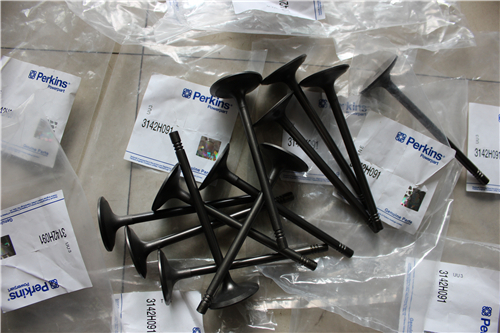
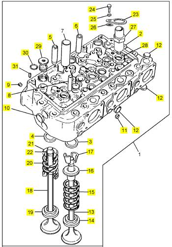
Perkins3012柴油发动机威尔逊P850E柴油发电机配件气门
详细描述
项目 零配件号码 最近的部分号码 描述
1 CV19169 4 CV19169 摇杆砂箱组合
15 ST46614 32 ST46614 CAPSCREW
16 CV20376 4 CV20376 密封垫
17 OE52035 24 CV24523 结桥
20 ST43563 32 ST43563 螺拴
21 2134 A010 32 2134 A010 垫圈
22 2131 A010 32 2131 A010 垫圈
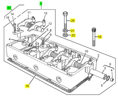
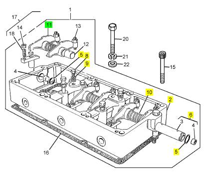
项目 零配件号码 最近的部分号码 描述
2 CV8160/2 Z 1 CV8160/2 Z 摇杆桥 ASSY-
2 1 砂箱
5 ST47452 10 ST47452 气门座圈
6 CV2255 8 CV2255 垫圈
7 CV1619 2 CV1619 密封O型圈
8 CV593 1 CV593 螺旋
9 2131 A008 1 2131 A008 垫圈
9 2134 A008 1 2134 A008 垫圈
10 OE43641 3 OE43641 摇杆桥弹簧
11 CV1913 6 CV1913 摇臂组合
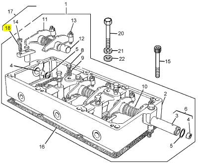
项目 零配件号码 最近的部分号码 描述
1 结桥
OE42556 1 OE42556 钮扣
18 OE41798 1 OE41798 螺旋
19 OE42293 1 OE42293 锁紧螺母
项目 零配件号码 最近的部分号码 描述
1 CV19716 4 CV24952/3 汽缸盖组合
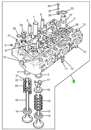
项目 零配件号码 最近的部分号码 描述
2 1 汽缸盖
3 CV7699 6 CV20814 气门座圈
3 CV14128 1 CV21069 气门座圈
4 OE43633 6 CV20815 气门座圈
4 OE47574 1 CV21070 气门座圈
5 OE47572 6 OE47572 气门导管
6 OE47573 6 OE47573 气门导管
8 OE43636 6 OE43636 气门导管
9 ST20701 1 ST20701 栓塞
10 ST43322 9 ST43322 栓塞
11 ST43309 3 ST43309 栓塞
12 ST43317 10 ST43317 栓塞
13 CV17435 6 CV21058 进气门
14 CV19281 6 CV19281 密封 - 阀转杆
15 CV11403 6 CV11403 阀弹簧
16 OE43262 6 OE43262 位子
17 OE42571 12 OE42571 阀筒夹
18 CV17434 6 排气阀
19 CV19282 6 密封
20 CV11403 6 CV11403 阀弹簧
21 CV19269 6 帽
22 OE42570 12 OE42570 阀筒夹
23 CV19679 3 CV19679 锁定板
24 2314 J003 3 2314 J003 螺旋
25 ST43161 3 2134 A010 弹簧塾圈
26 ST43057 3 2131 A010 垫圈
27 CV19681 3 CV19681 套筒
28 ST10609 3 ST10609 密封O型圈
29 OE43640 3 OE43640 栓塞
30 ST10603 3 ST10603 密封O型圈
31 ST45778 2 ST45778 弹簧销
10
Useful information
To clean components
It is important that the work area is kept clean and that
the components are protected from dirt and other
debris. Ensure that dirt does not contaminate the fuel
system.
Before a component is removed from the engine,
clean around the component and ensure that all
openings, disconnected hoses and pipes are sealed.
Remove, clean and inspect each component
carefully. If it is usable, put it in a clean dry place until
needed. Ball and roller bearings must be cleaned
thoroughly and inspected. If the bearings are usable,
they must be flushed in low viscosity oil and protected
with clean paper until needed.
Before the components are assembled, ensure that
the area is as free from dust and dirt as pos sible.
Inspect each component immediately before it is
fitted, wash all pipes and ports and pass dry
compressed air through them before connections are
made.
Use suitable gloves for protection when components
are degreased or cleaned with trichloroethylene,
white spirit, etc. Degreasing solutions which are
basically trichloroethane are not rec ommended.
16
Perkins Engines Company Limited
This document has been printed from SPI². Not for Resale
Suitable fluids to clean and to protect
components
Warning! Full information for the use of all the
products listed below and for their safe disposal, and
especially for the health and safety of the personnel
who use them, will be found in the Manufacturer’s
data.
Ardrox 667: Ardrox Limited, Brentford, Middlesex.
Maxan 774:Henkel Chemicals Limited, Edgeware
Road, London.
These products are basically methy lene chloride and
are safe to use on most metals for the removal of
carbon and to remove paint. They can damage
rubber and most plastic materials.
Method of use
The components to be degreased must be lowered
completely into the degreasing solution. Allow
enough time to elapse for the components to be
thoroughly cleaned. Subsequently, the components
must be thoroughly flushed in clean water. In use,
maintain a layer of water at least 76 mm (3 inches)
deep above the cleaning fluid to ensure that vapour
and toxic gases are not released.
Warning! Do NOT smoke near the container.
Protection for the eyes and for the skin must be used
always during the use of these fluids, and the
container must be in a place with good ventilation.
Duroclean 150 powder: Diversey Limited,
Northampton.
This product is basically an alkaline degreasing
solution and is safe to use on brass, copper and
ferrous metals. It must not be used on aluminium,
lead, tin or zinc.
Method of use
It is recommended that Duroclean 150 is used with a
maximum concentration of 50 grams for each litre of
water. The components to be degreased must be
lowered completely into the degreasing solution
which is heated to 65°C.
10
Leave to soak until all contamination has been
removed.
Subsequently, the components must be thoroughly
flushed in clean water. If neces sary, a suitable
corrosion inhibitor can be added to the last quantity of
water.
Warning! Protection for the eyes and for the skin
must be used always during the use of this product.
Crodafluid CR2: Croda Chemicals Limited, Goole,
Yorkshire.
This product is basically an acid solution with a
corrosion inhibitor. It is used to remove corrosion
from components that are made of ferrous metals.
Method of use
Crodafluid CR2 must be contained in a tank that is
made from a material which is not affected by acid.
Before the process begins, the components must be
degreased before they are lowered completely into
the Crodafluid solution. For medium to heavy
deposits of corrosion, the solution can be heated to
70°C. Inspect the components now and then to check
the results of the process. Surface corrosion can be
removed in a short period of time. The last operation
is to wash thoroughly the components in clean water.
Warning! Protection for the eyes and for the skin
must be used always during the use of this product.
Diverspray 30: Diversey Limited, Northampton.
This product is a moderate and basically alkaline
compound with corrosion inhibitors. It is either
sprayed over the components to clean them, or is
contained in a tank, for the immersion and agitation of
the components.
Diverspray 30 may be added to water to wash
components if a corrosion inhibitor is necessary. It is
used after other processes, such as corrosion
removal, are finished.
Perkins Engines Company Limited
17
This document has been printed from SPI². Not for Resale
10
NALCO 2568 Powder: NALCO Limited, PO Box 11,
Winnington Avenue, Northwich CW8 4DX
This product (which is supplied only in quantities of 25
kg) is an inhibited sulphamic acid and can be used for
the removal of hard deposits from the tube stack of
the oil cooler.
Warning! The solution must be made and used in
accordance with the manufacturer’s instructions.
The NALCO 2568 powder should be mixed with clean
fresh water in the ratio which follows:
15 - 40 kg/Tonne of water
(15 - 40 lb/100 UK gallons of water)
When the action of the solution is finished, dip the
tube stack in a solution made from: 0,5 kg (1 lb) of
sodium carbonate to 25 litres (5 UK gallons) of hot
water. The final operation is to dry the inside of the
tubes with compressed air.
Oil seals
Apply petroleum jelly to oil seals before they are fitted,
and do not damage the lip of the seal on sharp edges.
Unless other specifications apply, fit the seal with the
edge of the lip toward the bearing.
Hose connections
Do not use a screwdriver to remove hoses by force
because adaptors or pipe connections c an be
damaged. Cut through the hose and then cut the
ends of the hose from the adaptor or pipe connection.
When a new hose is fitted, a suitable rubber lubricant
can be used instead of antifreeze, water or french
chalk. Never lubricate a hose with oil or grease.
Gaskets, joints and ’O’ rings
Discard all used items if an engine or a component is
dismantled and fit only new and correct parts.
If a jointing compound is needed, ’Hylomar PL 32’
jointing compound is recommended for use, but on
metal joints ONLY. Only a thin application is needed,
an excessive quantity of compound can restrict the
flow of fluids in pipes and passages.
Caution: ’Hylomar’ jointing compound must NOT be
used in contact with any fibre joints as the solvent
contained in ’Hylomar’ can damage the joint material.
Apply a small amount of a suitable lubricant to ’O’ ring
seals to prevent damage during assembly.
18
Perkins Engines Company Limited
This document has been printed from SPI². Not for Resale
 10
10
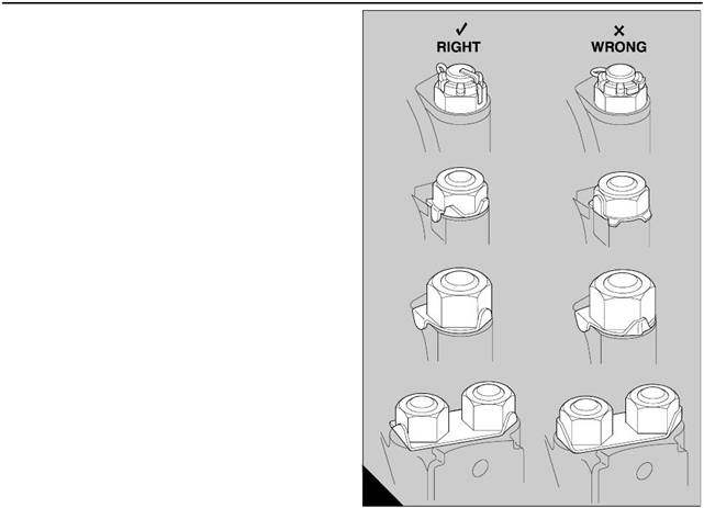
Locking devices
Split pins, lock plates and tab was hers which have
been used must be discarded. Various methods to
retain securely the nuts of an engine are shown (A).
Stiffnuts can be used again only if they have not lost
their grip and the original torque is needed to turn
them.
There must be a minimum protrusion of one full
thread of the bolt or stud through the stiffnut when it is
tightened fully. Discard all stiffnuts which have nylon
or fibre inserts.
Application of thread locking compounds
Remove all oil, grease and dirt from engine parts
before thread locking compounds are applied to
them. Most thread locking compounds have a date by
which they must be used, ensure that the compounds
used are within those dates.
Fits and clearances
The dimensions given in section 11C are acceptable
limits. The components which have measurements
within these limits are acceptable for a complete
period of service.
Certain components which are worn by more than
these limits can be corrected in accordance with a
Service Reclamation Scheme (SRS). Information
A
122
about the Service Reclamation Schemes is available
from the Serv ice Department at Perkins Engines
(Shrewsbury) Limited.
Applied torques
The specifications for applied torques, which are
given in section 11B, apply to some bolts and nuts
where damage or failure can occur if they are
incorrectly tightened. Where joints are fitted, for
example, between the cylinder head and the
crankcas e, it is also important that bolts and nuts are
tightened evenly and gradually as instructed in the
assembly sequence. The torque wrenches, listed
below, are s uitable for the torque load requirements of
the 3012/CV12 engine, and are available from
Perkins Distributors.
8 to 54 Nm (6 to 40 lbf ft), 21825 846
30 to 150 Nm (20 to 110 lbf ft), 21825 991
70 to 310 Nm (50 to 230 lbf ft), 21825 992
Perkins Engines Company Limited
19
This document has been printed from SPI². Not for Resale
10
Checks for cracks
When possible, it is recommended that components
which are affected by high stresses such as the
crankshaft, the connecting rods, the gears and the
cylinder liners are tested for cracks during overhaul.
They should also be checked for cracks when they
have been affected by an excessive load or impact. It
is recommended that ferrous components are tested
by the electro-magnetic method if possible. Portable
electro-magnetic test equipment is available from
Radalloyd Limited, Oadby, Leicester. Non-ferrous
components can be tested by the use of a dye
penetrant process such as ’Ardrox 996’, available
from Ardrox Limited, Brentford, Middlesex. The dye
penetrant must conform to one of the standards listed
below:
MIL-STD 271-E
MIL-L 25135
B.S. 5750
D.T.D. 929
Exchange units
It is recommended that unserviceable units are
returned, as complete as the new exchange unit, with
covers fitted to all openings and the joint faces
protected. When necessary, protec t the unit, both
inside and outside, from corrosion.
Parts
To ensure maximum reliability, fit only genuine
PERKINS parts supplied by a PERKINS distributor.
These parts are made to the latest specification and
have a guarantee for 12 months. The use of parts,
such as filter elements, which do not conform to
PERKINS standards, may reduce the life of the
engine and can affect the warranty.
If you need parts, spares or information for your
engine, give the complete engine number to your
Perkins distributor. This will ens ure that the correct
parts can be obtained.
20
Perkins Engines Company Limited
This document has been printed from SPI². Not for Resale
Approved lubricants and fluids
Equivalent lubricants and fluids of other manufacturers are acceptable
10
|
Product or specification Manufacturer |
|
Alternator Cleaning fluid for diodes Fluid grade 8-23 Applied Chemicals Limited Grease for diodes Silicon MS200, MS4 and MS5 Applied Chemicals Limited Camshafts Anti-seize compound Rocol J166 Rocol Limited Anti-scuffing paste Rocol Cooling system Lips of oil seal in coolant pump Shell Alvania R3 Grease Shell Oils Hose and ‘O’ rings Liner lubricant Morris’s Shrewsbury Compound for cleaning the system Lissapol ‘N’, 1% I.C.I Limited (10 cc/ltr - 45 cc /Imp. gallon) Lissapol ‘NDB’, 2% (20 cc/ltr - 90 cc /Imp. gallon) To remove hard deposits from the oil NALCO 2568 powder NALCO Limited cooler (in 25 kg drums only) Exhaust system Anti-seize compound for threads Copaslip Slip Group Rocol Limited Rocol J166 Joints Jointing compound Hylomar Silicone Sealant Marston Bentley Limited Adhesive and Sealants Division, Wigan Sealant and thread locking Loctite AVV, 241, 270, 290, Douglas Kane Sealants 542 and 601 Morris’s Shrewsbury Shell Oils Various Lubrication system ‘O’ rings and relevant bores Liner lubricant Morris’s Shrewsbury Starter motor Cleaning fluid for commutators White spirit Lubricant for splines Aeroshell DID5598 Shells Oils ‘O’ ring lubricant Glycerine Lubricator wick Mineral oil Various SAE 5W/20 |
Perkins Engines Company Limited
21
This document has been printed from SPI². Not for Resale
10
22
Perkins Engines Company Limited
This document has been printed from SPI². Not for Resale
11
Specifications
Basic engine data
Engine
11
Number of cylinders . . . . . . . . . . . . . . . . . . . . . . . . . . . . . . . . . . . . . . . . . . . . . . . . . . . . . . . . . . . . . . . . . . 12
Cylinder arrangement . . . . . . . . . . . . . . . . . . . . . . . . . . . . . . . . . . . . . . . . . . . . .60 degree included angle ‘V’
Cycle. . . . . . . . . . . . . . . . . . . . . . . . . . . . . . . . . . . . . . . . . . . . . . . . . . . . . . . . . . . . . . . . . . . . . . . . Four stroke
Induction system . . . . . . . . . . . . . . . . . . . . . . . . . . . . . . . . . . . . . . . . . . . . . Turbocharged and charge cooled
Combustion system . . . . . . . . . . . . . . . . . . . . . . . . . . . . . . . . . . . . . . . . . . . . . . . . . . . . . . . . .Direct injection
Nominal bore . . . . . . . . . . . . . . . . . . . . . . . . . . . . . . . . . . . . . . . . . . . . . . . . . . . . . . . . . . . . 135 mm (5.315 in)
Stroke . . . . . . . . . . . . . . . . . . . . . . . . . . . . . . . . . . . . . . . . . . . . . . . . . . . . . . . . . . . . . . . . . . 152 mm (5.984 in)
Compression ratio. . . . . . . . . . . . . . . . . . . . . . . . . . . . . . . . . . . . . . . . . . . . . . . . . . . 26,11 litres (1593.24 in³)
Cubic capacity . . . . . . . . . . . . . . . . . . . . . . . . . . . . . . . . . . . . . . . . . . . . . . . . . . . . . . . . . . . . . . . . . . . . 14.5:1
Firing order . . . . . . . . . . . . . . . . . . . . . . . . . . . . . . . . . . . . . . A6, B1, A3, B4, A5, B2, A1, B6, A4, B3, A2, B5
Tappet clearances (hot or cold) . . . . . . . . . . . . . . . . . . . . . . . . . . . . . . . . . . . . . . . . . . . . . . . . . . . . . . . . . . .
Engines before ‘build line number’ 8281
(6C27437/29):
Inlet valves . . . . . . . . . . . . . . . . . . . . . . . . . . . . . . . . . . . . . . . . . . . . . . . . . . . . . . . . . . . . 0,4 mm (0.016 in)
Exhaust valves . . . . . . . . . . . . . . . . . . . . . . . . . . . . . . . . . . . . . . . . . . . . . . . . . . . . . . . . . 0,5 mm (0.020 in)
Engines from ‘build line number’ 8281
(6C27437/29):
Inlet valves . . . . . . . . . . . . . . . . . . . . . . . . . . . . . . . . . . . . . . . . . . . . . . . . . . . . . . . . . . . . 0,2 mm (0.008 in)
Exhaust valves . . . . . . . . . . . . . . . . . . . . . . . . . . . . . . . . . . . . . . . . . . . . . . . . . . . . . . . . . 0,5 mm (0.020 in)
Direction of rotation . . . . . . . . . . . . . . . . . . . . . . . . . . . . . . . . . . . Anti-clockwise from the rear of the engine
Injection timing . . . . . . . . . . . . . . . . . . . . . . . . . . . . . . . . . . . . . . . . . . . . . . As stamped on engine data plate
Rated power output. . . . . . . . . . . . . . . . . . . . . . . . . . . . . . . . . . . . . . . . . . . . . . . . . . . . . . . . . . 400 to 740 kW
Maximum rated speed. . . . . . . . . . . . . . . . . . . . . . . . . . . . . . . . . . . . . . . . . . . . . . . . . . . . . . . . . 1800 rev /min
Dry weight of engine . . . . . . . . . . . . . . . . . . . . . . . . . . . . . . . . . . . . . . . . . . . . . . . . . . . . . . 2120 kg (4674 lb)
(Approximate)
Dry weight of electropak
(Approximate)
3012 TG . . . . . . . . . . . . . . . . . . . . . . . . . . . . . . . . . . . . . . . . . . . . . . . . . . . . . . . . . . . . . . 2365 kg (5214 lb)
3012 TAG . . . . . . . . . . . . . . . . . . . . . . . . . . . . . . . . . . . . . . . . . . . . . . . . . . . . . . . . . . . . . 2315 kg (5103 lb)
Perkins Engines Company Limited
23
This document has been printed from SPI². Not for Resale
11
Cooling system
Type. . . . . . . . . . . . . . . . . . . . . . . . . . . . . . . . . . . . . . . . . . . . . . . . . . . . . . . . . . . . . . . . . . . . . . . .Liquid cooled
Coolant pump. . . . . . . . . . . . . . . . . . . . . . . . . . . . . . . . . . . . . . . . . . . . . . . . . . . . Centrifugal unit, gear-driven
Capacities for coolant
Engine and pipes . . . . . . . . . . . . . . . . . . . . . . . . . . . . . . . . . . . . . . . . . . . . . . . . . . 68 litres (15 UK gallons)
Engine/radiator pack . . . . . . . . . . . . . . . . . . . . . . . . . . . . . . . . . . . . . . . . . . . . . 122,7 litres (27 UK gallons)
Coolant system pressure . . . . . . . . . . . . . . . . . . . . . . . . . . . . . . . . . . . . . . . . . . . Up to 69 kN/m² (10 lbf/in²)
Temperature (normal) . . . . . . . . . . . . . . . . . . . . . . . . . . . . . . . . . . . . . . . . . . . . . . . . . . . . . . . . . 70° to 100°C
Thermostats . . . . . . . . . . . . . . . . . . . . . . . . . . . . . . . . . . . . . . . . . . . . Two, single element, wax capsule type
Cooling fan. . . . . . . . . . . . . . . . . . . . . . . . . . . . . . . . . . . . . . 1220 mm (48 in) diameter, 8 blades, belt driven
Approved coolant . . . . . . . . . . . . . . . . . . . See section 5 - ‘Engine fluids’ in the User’s Handbook TSD 3138
Fuel system
Type. . . . . . . . . . . . . . . . . . . . . . . . . . . . . . . . . . . . . . . . . . . . . . . . . . . Low-pressure supply to injection pump
with return of spill fuel to the tank
Fuel injection pump. . . . . . . . . . . . . . . . . . . . . . . . . . . . . . . . . . . . . . . . . . . . . . . . . . . .12 element in-line unit
Governor. . . . . . . . . . . . . . . . . . . . . . . . . . . . . . . . . . . Mechanical, servo assisted, integral with fuel injection
pump, constant speed for operation of generators
(for other applications, variations are fitted)
Fuel lift pump . . . . . . . . . . . . . . . . . . . . . . . . . . . . . . . . . . . . . . . . . . . . . . . Mechanical, operated by camshaft
Fuel supply pressure. . . . . . . . . . . . . . . . . . . . . . . . . . . . . . . . . . . . . . . . . 140 to 210 kN/m² (20 to 30 lbf/in²)
Fuel injectors . . . . . . . . . . . . . . . . . . . . . . . . . . . . . . . . . . . . . . .Axial supply, low spring type, six spray holes
Injection pressure . . . . . . . . . . . . . . . . . . . . . . . . . . . . . . . . . . . . . . . . . . . . . 250 bar (early engines 240 bar)
Main fuel filters. . . . . . . . . . . . . . . . . . . . . . . . . . . . . . . . . . . . . . . . . . . . . . . . . . Two screw-on type canisters
Approved fuel . . . . . . . . . . . . . . . . . . . . . . . . . . . . . . . . . . . . . . . . . . . . . . . . . . . . . . . . . . . . . .Centrifugal type
Approved fuel . . . . . . . . . . . . . . . . . . . . . . . . . . . . . . . . . . . . . . . . See section 5 - ‘Engine fluids’ in the User’s
Handbook TSD 3138
24
Perkins Engines Company Limited
This document has been printed from SPI². Not for Resale
Lubrication system
11
Type . . . . . . . . . . . . . . . . . . . . . . . . . . . . . . . . . . . . . . . . . . . . . . . . . . . . . . . . . . . . . . . . . . . . . . . . . Wet sump
Capacities
Sump maximum. . . . . . . . . . . . . . . . . . . . . . . . . . . . . . . . . . . . . . . . . . . . . . . . . . . . . . 55 litres (12 UK gallons)
Sump minimum . . . . . . . . . . . . . . . . . . . . . . . . . . . . . . . . . . . . . . . . . . . . . . . . . . . . . . 33 litres (7.3 UK gallons)
System total. . . . . . . . . . . . . . . . . . . . . . . . . . . . . . . . . . . . . . . . . . . . . . . . . . . . . . 73.8 litres (16.2 UK gallons)
Pressure
Normal load conditions . . . . . . . . . . . . . . . . . . . . . . . . . . . . . . . . . . . . . . . . . . . . . . . . . . 448 kN/m² (65 lbf/in²)
Minimum at rated s peed . . . . . . . . . . . . . . . . . . . . . . . . . . . . . . . . . . . . . . . . . . . . . . . . . 345 kN/m² (50 lbf/in²)
Pump. . . . . . . . . . . . . . . . . . . . . . . . . . . . . . . . . . . . . . . . . . . . . . . . . . . . . . . . . . . .Spur gear type, gear driven
Pressure relief valve . . . . . . . . . . . . . . . . . . . . . . . . . . . . . . . . . . . . . . .Spring loaded plunger, not adjustable
Opening pressure . . . . . . . . . . . . . . . . . . . . . . . . . . . . . . . . . . . . . . . . . . . . . . . . . . . . . . 488 kN/m² (71 lbf/in²)
Oil-to-coolant heat exchanger . . . . . . . . . . . . . . . . . . . . . . . . . . . . . Tube stac k and body, with baffle plates
Filters . . . . . . . . . . . . . . . . . . . . . . . . . . . . . . . . . . . . . . . . . . . . . . . . . . . . . . . . Three screw-on type canisters
Maximum recommended temperature
of oil in sump . . . . . . . . . . . . . . . . . . . . . . . . . . . . . . . . . . . . . . . . . . . . . . . . . . . . . . . . . . . . . . . . . . . . . 125°C
Approved lubricating oil . . . . . . . . . . . . . . See section 5 - ‘Engine fluids’ in the User’s Handbook TSD 3138
Induct ion and exhaust systems
Aspiration. . . . . . . . . . . . . . . . . . . . . . . . . . . . . . . . . . . . . . . . . . . . . . Pressure charged by two turbochargers
Air charge coolers . . . . . . . . . . . . . . . . . . . . . . . . . . . . . . . . . . . . . . Two, air to air type, integral with radiator
Air filters. . . . . . . . . . . . . . . . . . . . . . . . . . . . . . . . . . . . . . . . . . . . . . . . . . . . . . . . . . .Two, paper element type
Electrical equipment
Alternator . . . . . . . . . . . . . . . . . . . . . . . . . . . . . . . . . . . . . . . . . . . . . . . . . . . . . . . . . . . . . . . 24 volt 40 ampere
Starter motor . . . . . . . . . . . . . . . . . . . . . . . . . 24 volt - flange fitted (certain engines have two s tarter motors)
Stop control . . . . . . . . . . . . . . . . . . . . . . . . . . . . . . . . . . . . . . . . . . . . . . . . . . . . . . . . 24 volt, energised-to-run
Engine protection switches . . . . . . . . . . . . . . . . . . . . . . 24 volt instrument sender/switches for oil pressure,
coolant temperature and coolant level
Perkins Engines Company Limited
25
This document has been printed from SPI². Not for Resale
11
Recommended specific applied torques
Caution: The torque loads listed below apply to threads in an oil wet condition, unless the use of thread
locking compound is recommended.
Application of a torque specification is NOT enough to ensure that the relevant components are retained
securely as an assembly. It is important to conform also to the recommendations for assembly and, if given,
the sequence in which the bolts or nuts must be tightened. This information is given in the relevant section of
this publication.
If a bolt or nut is retained with a locking washer, lock plate or split pin, the specification for a torque load can
be exceeded, if nec essary, by the MINIMUM amount that is needed for correct assembly.
Nm lbf ft
Alternator
Nut, pulley 95 70
Auxiliary drive shaft
Nut, flange (18 mm 27 A/F) 200 300
(22 mm 32 A/F) 300 221
Camshafts 200 to 250 148 to 184
Bolts, camshaft gear ‘A’ bank 217 160
‘B’ bank
Screws, countersunk head, thrust plate 24 18
Connecting rods
Nuts, big end bearing 60 44
(Caution - refer to operation 13-1)
Crankcase
Bolts, main bearing cap
Front, centre and rear 177 131
Others 488 360
Side bolts, main bearing cap
Front, centre and rear 114 84
Others 177 131
Studs, cylinder head 315 232
Crankshaft
Bolts, damper and pulley 80 59
Cap screws, flywheel 315 232
Cylinder heads
Bolts, cylinder head to crankcase
Bolts in induction ports only 200 148
All other long bolts 240 148
(plus a further 90°)
Nuts, cylinder head to crankcase (earlier engines) 200 148
(plus a further 90°)
Bolts, rocker box to cylinder head 46 34
Cap screws, rocker box to cylinder head 35 26
Bolts, roc ker box cover to rocker box 23 17
Lock nut, adjustment screw, bridge piece 40 30
26
Perkins Engines Company Limited
This document has been printed from SPI². Not for Resale
Lock nut, adjustment s crew, tappet
Bolt, location, rocker shaft
Coolant Gallery
Bolts and nuts
Coolant pump
Lock nut, bearing
Nut, drive gear
Exhaust manifolds
Bolts
Fan adaptor
Nuts, bearing
Flywheel housing
Bolts, flywheel housing to timing case
Bolts, (2) flywheel housing to crankcase
(later engines with steel crankcase/timing case joints)
Fuel filter head
Bolts, bracket to crankcase
Fuel injection pump
Cap screws, adjustable coupling (earlier engines)
Special bolts, adjustable coupling (later engines)
Nut, hub, camshaft
Holders, delivery valve
Bolts, pump to mounting
Nuts, c oupling, plate, spring
Fuel injectors
Cap screws, clamp
Cap nut, nozzle
Connection, spill pipe, new type (directly onto fuel injector)
Connection, spill pipe, new type (directly onto fuel injector)
Fuel lift pump (mechanical)
Nut, cam to auxiliary drive shaft
High pressure fuel pipes
Nuts, high pressure fuel pipes
Gears
Bolts, auxiliary drive gear
Bolts, compound idler gear
Bolts, axle, double idler gear
Bolts, axle, idler gear, main
Bolt, axle, idler gear, coolant pump
Bolt, axle, idler gear, oil pump
Induction manifolds
Bolts, induction manifolds
Perkins Engines Company Limited
Nm
40
15
23
100
88
46
280
80
95
70
46
149
122
46
120
60
80
27
17
54
45
58
40
135
135
135
135
46
lbf ft
30
11
17
74
65
34
207
,59
70
52
34
110
90
34
88
80
59
20
12
40
33
43
30
100
100
100
100
34
11
27
This document has been printed from SPI². Not for Resale