 English
 Espaol
 Franais
 阿拉伯
阿拉伯 中文
中文 Deutsch
 Italiano
 Português
 日本
日本 韩国
韩国 български
 hrvatski
 esky
esky Dansk
Dansk Nederlands
 suomi
suomi Ελληνικ
 印度
印度 norsk
norsk Polski
 Roman
Roman русский
 Svenska
Perkins3012柴油发动机威尔逊P850E柴油发电机配件活塞、活塞环供应商,Perkins3012柴油发动机威尔逊P850E柴油发电机配件活塞、活塞环技术价格规格咨询服务,Perkins3012柴油发动机威尔逊P850E柴油发电机配件活塞、活塞环零配件供应,Perkins3012柴油发动机威尔逊P850E柴油发电机配件活塞、活塞环售后服务中心,Perkins3012柴油发动机威尔逊P850E柴油发电机配件活塞、活塞环,Perkins3012柴油发动机威尔逊P850E柴油发电机配件活塞、活塞环详细的技术参数,

产品中心
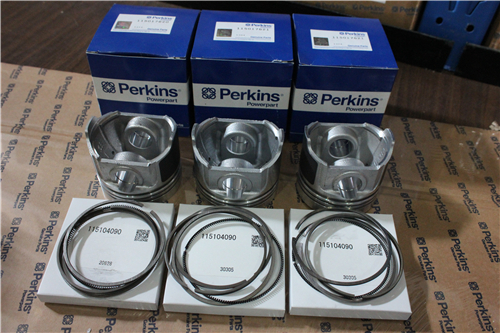
Perkins3012柴油发动机威尔逊P850E柴油发电机配件活塞、活塞环
详细描述
项目 零配件号码 最近的部分号码 描述
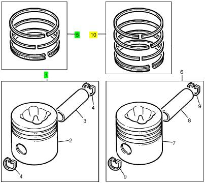
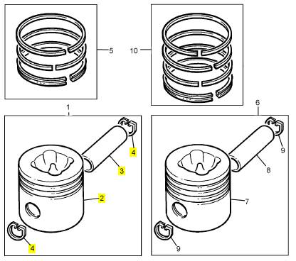
1 CV19976/1 12 CV19976/1 活塞装备
5 CVK564 12 CVK564 活塞环装备
10 CVK502 12 CVK502 活塞环装备
项目 零配件号码 最近的部分号码 描述
2 1 活塞
3 1 桥头销
4 CV565 2 CV565 CIRCLIP
4 CV19330 2 CV19330 CIRCLIP
项目 零配件号码 最近的部分号码 描述
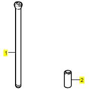
1 CV285 24 CV285 PUSHROD
2 CV70122 24 CV70122 挺杆
2 CV65451 24 CV70122 挺杆
项目 零配件号码 最近的部分号码 描述
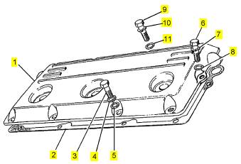
1 CV19148 4 CV19148 汽缸盖盖
2 CV20400 4 CV20400 密封 - 摇杆的砂箱盖
3 2314 C045 16 2314 C045 固定螺钉
4 2134 A008 16 2134 A008 垫圈
5 2131 A008 16 2131 A008 垫圈
6 ST43502 8 ST43502 螺拴
7 2134 A008 8 2134 A008 垫圈
8 2131 A008 8 2131 A008 垫圈
9 ST43504 16 ST43504 螺拴
10 2134 A008 16 2134 A008 垫圈
11 2131 A008 16 2131 A008 垫圈
11
Lubricating oil pump
Bolts, casing
Nut, drive gear
Lubricating oil sump
Bolts
Insert, drain plug
Drain plug (sump with insert - early engines only)
Drain plug (single piece sump without insert)
Timing case
Bolts, timing case to crankcase
Bolts and nut (early engines)
Bolts and cap screws (later engines)
Bolts, timing case to sump
Bolts (early engines )
Bolts (later engines with steel joints)
Recommended nominal applied torques
Nm
23
120
55
325
115
47
95
135
55
75
lbf ft
17
89
41
240
85
35
70
100
40
55
Where instructions are not given for the correct torque to be applied to nuts and bolts, the figures which follow
should be used.
Bolt siz e Nm lbf ft
M5 6 4.5
M6 9.5 7
M8 23 17
M10 46 34
M12 80 59
M14 127 94‘
M16 198 146
M18 273 201
M20 387 285
M22 526 388
M24 669 493
28
Perkins Engines Company Limited
This document has been printed from SPI². Not for Resale
 12
12
Cylinder head assembly
General description
12
The four cylinder heads, which are all the same, are
made from high quality cast iron and are retained by
bolts or by studs on early engines. They are machined
on the top and bottom faces for the rocker box and the
cy linder head gaskets respectively. Joint faces are
machined on the inner and outer sides for the
induction and the exhaust manifolds. There are
passages for coolant in the cylinder head around the
valve guides and the pockets for the fuel injectors.
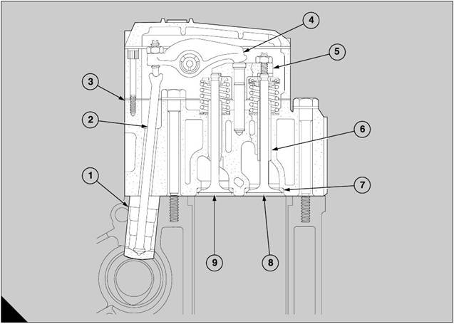
The valve guides (A6) are made from an alloy of high
quality nickel chromium and are a press fit in the
cy linder head. The valve seat inserts (A7) are cooled
and pressed into recesses which are machined in the
cy linder heads.
A
375
Perkins Engines Company Limited
29
This document has been printed from SPI². Not for Resale
 12
12
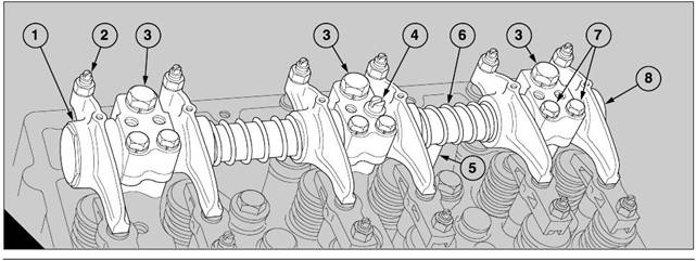
The inlet valves (A9) are made from steel forgings.
The exhaust valves (A8) are made from solid
’Nimonic’ material. The valves are retained with
collets, springs and spring seat washers. Exhaust
valves are fitted with valve rotators instead of upper
spring seat washers. Each set of two valves is
actuated by a bridge piece (A5) which moves on a
guide. There is an adjustment screw and a lock nut
on the outer arm of each bridge piece. A nitrided
button is inserted in the top face of each bridge piece
and connects with its rocker lever (A4). Each rocker
lever is operated by the camshaft through a push rod
(A2) and a tappet (A1).
The rocker levers (A4) hav e adjustment sc rews and
lock nuts for the tappet clearances. For early
engines, they are ass embled on a rocker shaft in
each rocker box and are separated by the springs.
The rocker boxes are held in the correct positions on
the cylinder heads by spring dowels and are retained
with socket head cap screws and bolts, tightened to a
specific torque. The rocker box covers are made from
castings of aluminium and are retained by bolts. The
new rocker box covers of these engines are retained
with an extra bolt at each end.
Three fuel injec tors in each cylinder head are retained
by clamps and cap screws. The connec tions for the
fuel supply and the surplus fuel are sealed at the
rocker box covers and the walls of the rocker boxes
respectively, to prevent leakage of oil and the entry of
dirt.
Note: For the illustration (A), inlet and exhaust valves
are shown under the same bridge piece.
A
375
30
Perkins Engines Company Limited
This document has been printed from SPI². Not for Resale
![]() New engines, from engine number 6A28293, do not
New engines, from engine number 6A28293, do not
have rocker boxes and each rocker shaft is mounted
on three pedestals whic h are bolted to the relevant
cy linder head. A rocker cover, formed in Vynalester,
encloses the rocker assembly. Bolt holes are sealed
with rubber washers and the interface with the
cy linder head is sealed with a special rubber sealing
ring.
For these engines, a new type of fuel injector is used.
These fuel injec tors are longer and have the
connections for the leak-off fuel above the rocker
covers.
A single cylinder head may be removed from the
engine and given an overhaul while the engine is still
connected to its relevant driven unit. In this situation,
ensure that the batteries are disconnected.
Pedestal rocker cover
12
1 Ensure that the seal is fitted correctly into the
groove around the pedestal rocker cover, put the
pedestal rocker cover on the cylinder head and fas ten
it to two of the pedestals by the two short bolts with
sealing washers. Do not tighten the bolts.
2 Fit the five long bolts, with sealing washers, through
the pedestal rocker cover into the cylinder head.
Tighten lightly all of the bolts.
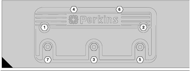
3 Tighten evenly all the bolts in the sequence shown
(A) to a torque of 11 Nm (8 lbf ft).
4 Fit all other components which were removed, in
reverse sequence to their removal.
To remove and to fit
To remove
1 Disconnect the batteries.
12-1
2 Release the banjo connection bolts from the fuel
injectors and remove the relevant high pressure pipes
for the fuel supply from the fuel injection pump to the
fuel injectors.
3 Remove the two s hort and five long special bolts
which retain the pedestal rocker cover and then
remove carefully the pedestal rocker cover.
To fit
New sealing washers should be fitted to the special
bolts and a new seal fitted to the pedestal rocker
cover.
A
70
Perkins Engines Company Limited
31
This document has been printed from SPI². Not for Resale
![]() 12
12
Pedestal rocker assembly
To remove and to fit
To remove
12-2
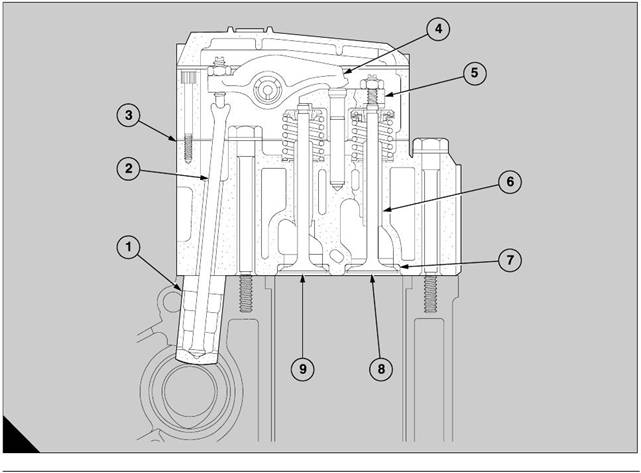
3 Fit a new ’O’ ring seal to each end of the lubricating
oil tube (A5) and lubricate the seals with engine
lubricating oil.
4 Turn the coils of the relevant spring (A6) to ensure
that there is clearance around the oil hole in the
rocker shaft and insert one end of the lubricating oil
tube into the hole. Ensure that the ’O’ ring seal is fitted
1 Remove the pedestal rocker cover, operation 12-1.
2 Loosen fully the adjustable screws of the roc ker
levers. Loosen the three bolts, each of which retains
one of the three pedestals, and lift v ertically away the
complete rocker assembly while holding the
lubricating oil tube which supplies the rocker shaft.
3 Remov e the lubricating oil tube from the rocker
shaft and ensure that the ’O’ ring seal at each end of
the tube is removed and discarded carefully.
4 Remov e the bridge pieces and the push rods, if
relevant.
5 If relevant to the job, remove the fuel injectors,
operation 20-7.
To fit
Note: After the pedestal rocker assembly has been
fitted, it is not possible to remove the bridge pieces
from either end of the cylinder head to tighten the
adjustment to the correct torque. If relevant to the job,
therefore, the bridge pieces must be set as instructed
in paragraphs 3 and 5 of operation 12-8 before this
operation is started.
1 If relevant, insert the extreme left hand push rod
through its opening in the cylinder head. If relevant,
give a full application of oil to the bridge pieces and
their guides and fit the bridge pieces onto their guides.
The other push rods may be fitted after the rocker
assembly is ins talled.
2 Ensure that the adjustment screws (A2) of the
rocker levers and the bridge pieces are loosened fully.
correctly and is not damaged. Hold the lubricating oil
tube in its position.
5 Lower the rocker assembly onto its cylinder head
and fit carefully the lubricating oil tube into its hole in
the cylinder head. Ensure that the ’O’ ring seal is fitted
correctly and is not damaged
6 Fit and tighten lightly the three bolts (A3) which
retain the pedes tals. If not already fitted, fit a spring
washer to the screw (A4) and fit the screw to the
tapped hole at the right of the central pedestal. Do not
tighten the screw. This screw controls the position of
the rocker shaft.
7 Check the end-float of each outer rocker lever (A1
and A8) with feeler gauges. Loosen the bolt which
retains each outer pedestal as necessary and adjust
its position to obtain the correct minimum clearance
of 0,12 mm (0.005 in). Tighten again the bolt and also
tighten the two s maller bolts (A7) which retain the
rocker shaft. It may be necessary to adjust also the
position of the central pedestal to obtain the correct
clearance at each end of the rocker shaft.
8 When the end-float at each end is correct, tighten
the three bolts to a torque of 80 Nm (59 lbf ft). Check
again the end float and tighten the two smaller bolts
on each pedestal to a torque of 23 Nm (17 lbf ft).
9 Tighten fully the sc rew (A4) in the central pedestal
which controls the position of the roc ker shaft.
A
207
32
Perkins Engines Company Limited
This document has been printed from SPI². Not for Resale
![]() 10 Turn the remainder of the bridge pieces 90°, lower
10 Turn the remainder of the bridge pieces 90°, lower
them between the valve assemblies and tilt each
To assemble
12
rocker lever to insert the push rods through the
openings in the cylinder head. Fit the adjustment
sc rew of each rocker lever into the socket of its push
rod and return the bridge piece to its original position
to retain the push rod.
11 Turn c lockwise the adjustment screws until they
are nearly at their normal position.
12 Adjust the tappet clearances, paragraphs 5 to 20
of operation 12-8.
13 If relevant to the job, fit the fuel injectors, operation
12-7.
14 Fit the pedestal rocker cover, operation 12-1.
To dismantle and to assemble 12-3
To dismantle
Before the assembly is dismantled, identify each
component with a temporary mark. Make a note of
the sequence of the assembly of the components to
ensure that they can be assembled again in the
same sequence and with the hole for the lubricating
oil tube in the correct position.
1 Remove the screw in the central pedestal which
controls the position of the rocker shaft.
2 Remove the setscrews from each end of the rocker
shaft.
Caution: During this operation, prevent damage to
the hexagon flats of the setscrews because the end-
float of the rocker levers next to them may be
affected. The hex agons are 36,00/35,75 mm A/F.
3 Loosen the two small screws which retain the
rocker shaft in each pedestal and slide off each
pedestal, each rocker lever and each spring as it
becomes free.
4 To inspect and to correct the components, refer to
operation 12-7.
Before the setscrews are fitted to the ends of the
rocker shaft, ensure that all deposits of old locking
agent have been remov ed and that the internal/
external threads have been degreased.
1 Apply lightly 'Loctite 542' to the threads of one
setscrew and fit the setscrew to one end of the rocker
shaft.
2 Refer to the notes already made and assemble the
components onto the rocker shaft in the correct
sequence with the hole for the lubricating oil tube in
the correct position. Apply lightly 'Loctite 542' to the
threads of the second setscrew and fit the setscrew to
the other end of the rocker shaft.
3 Hold the assembly by the hexagon of one setscrew
in a vice with soft covers and tighten the other
setscrew to a torque of 24 Nm (17.7 lbf ft) to ensure
that both setsc rews are tightened equally.
Caution: During this operation, prevent damage to
the hexagon flats of the sets crews bec ause the end-
float of the rocker levers next to them may be
affected. The hexagons are 36,00/35,75 mm A/F.
4 To move the components along the rocker shaft,
compress the springs and apply clean engine
lubricating oil to the contact faces. Turn the rocker
shaft until the direction of the oil hole in the rock er
shaft is downward (toward the cylinder head).
5 Fit a spring washer to the screw which has a
screwdriver slot and fit the screw fully into the tapped
hole at the right of the central pedestal. This screw
controls the position of the rocker shaft.
Perkins Engines Company Limited
33
This document has been printed from SPI². Not for Resale
![]() 12
12
Rocker box cover
To remove and to fit
To remove
1 Disconnect the batteries.
12-4
6 Check that the socket of each push rod and the
adjustment screw of its relevant rocker lever are
aligned correctly. Tighten, gradually and evenly,
each bolt to 46 Nm (34 lbf ft) and each cap sc rew to
35 Nm (26 lbf ft).
7 Adjust the tappet clearances, operation 12-8.
8 Fit the rocker box covers, operation 12-4.
2 Disconnect and remove the relevant high pressure
pipes for the fuel supply from the fuel injection pump
to the fuel injectors and then remove the rocker cover.
To fit
1 Fit all components which were removed, in reverse
sequence to their removal.
Rocker box
To remove and to fit
To remove
12-5
1 Remove the rocker box covers, operation 12-4.
2 If relevant, release the connections for the leak-off
fuel from the fuel injectors and remove them through
the wall of the rocker box.
3 Loosen fully the adjustable screws of the roc ker
levers. Loosen ev enly and gradually the bolts and the
cap screws which retain the rocker boxes.
4 When the pressure of the valve springs is released,
lift away each rocker box.
5 Remov e the bridge pieces and the push rods, if
relevant.
To fit
1 Make locally some s uitable guide studs and fit four
guide studs for each rocker box in their relevant
cylinder heads. Check that the two dowels which
provide the location for each rocker box are fitted into
the cylinder heads.
2 Ensure that the adjustment screws of the rocker
levers and the bridge pieces are loosened fully.
3 Insert the 6 push rods through the apertures of
each cylinder head. Give a full application of oil to the
push rods, the guides of the bridge pieces and the
bridge pieces, and fit the bridge pieces into their
guides.
4 Remov e all the oil from the joint face of eac h
cylinder head and fit carefully the new joints in their
correct positions.
5 Fit each roc ker box assembly onto its cylinder head
and fit the spherical foot of each rod in its tappet. Fit
the 8 bolts, with the plain washers and the spring
washers, followed by the 8 cap screws which retain
each rocker box.
34
Perkins Engines Company Limited
This document has been printed from SPI². Not for Resale
 To dismantle and to assemble
12-6
To assemble
12
To dismantle
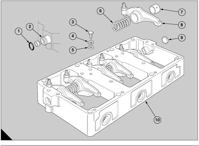
1 If relevant, remove the cup plug (A9) from the bore
for the shaft (A2) in the rocker box (A10).
2 Remove the bolt (A3) which retains the rocker shaft
and push the rocker shaft to the left, as seen from the
outer edge of the rocker box, until the ’O’ ring (A1) can
be removed from around the rocker shaft.
3 Continue to withdraw the rocker shaft and remove
each rocker lever (A8) and each spring (A6) as it
becomes free.
4 If a cup plug is not fitted in the bore of the rocker
box, push the rocker shaft enough in either direction
to remove one ’O’ ring and then push the rocker shaft
in the reverse direction to remove the second ’O’ ring.
5 Continue to withdraw the shaft and remove the
rocker levers and the springs as they become free.
1 If relevant, check that the bore for the cup plug in
the end of the rocker box is clean. Apply ’Loctite 542’
to a new cup plug and pres s it into the bore until it is
aligned with the wall of the rocker box.
2 Apply clean engine lubricating oil to the rocker shaft
and insert the end which has the opening into the bore
of the rocker box. Ensure that the oil hole in the
rocker shaft is facing directly downward (toward the
cylinder head).
3 Push the rocker shaft through the end, enough to fit
the first roc ker lever onto the rocker shaft. Continue to
push the rock er shaft through the rocker box and fit
the spring and the second rocker lever before the
rocker shaft enters the first pedestal. Fit the
remainder of the arms and springs in the correct
sequence.
4 Before the rocker shaft is pushed fully into its
correct position, fit the ’O’ ring in its groove around the
rocker shaft. Push further the rocker shaft until the
bolt hole in the rocker shaft is aligned with the
threaded hole in the pedestal. Fit the bolt that holds
the rocker shaft, with a plain washer (A5) and a spring
washer (A4), and tighten it sec urely.
A
339
Perkins Engines Company Limited
35
This document has been printed from SPI². Not for Resale