 English
 Espaol
 Franais
 阿拉伯
阿拉伯 中文
中文 Deutsch
 Italiano
 Português
 日本
日本 韩国
韩国 български
 hrvatski
 esky
esky Dansk
Dansk Nederlands
 suomi
suomi Ελληνικ
 印度
印度 norsk
norsk Polski
 Roman
Roman русский
 Svenska
Perkins3012柴油发动机威尔逊P850E柴油发电机配件机油冷却器供应商,Perkins3012柴油发动机威尔逊P850E柴油发电机配件机油冷却器技术价格规格咨询服务,Perkins3012柴油发动机威尔逊P850E柴油发电机配件机油冷却器零配件供应,Perkins3012柴油发动机威尔逊P850E柴油发电机配件机油冷却器售后服务中心,Perkins3012柴油发动机威尔逊P850E柴油发电机配件机油冷却器,Perkins3012柴油发动机威尔逊P850E柴油发电机配件机油冷却器详细的技术参数,

产品中心
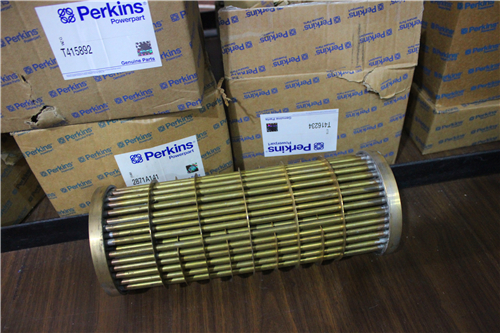
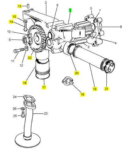
Perkins3012柴油发动机威尔逊P850E柴油发电机配件机油冷却器
详细描述
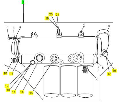
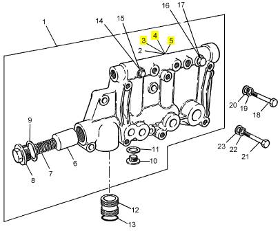
项目 零配件号码 最近的部分号码 描述
1 CV13140Z 1 CV13140Z 机油冷却器
10 ST46078 1 ST46078I 栓塞
11 ST49853 1 ST49853 垫圈
12 ST43622 3 ST43622 螺拴
13 2134 A012 3 2134 A012 垫圈
14 2131 A012 3 2131 A012 垫圈
15 ST10616 1 ST10616 密封O型圈
16 ST10609 3 ST10609 密封O型圈
17 ST46077 1 ST46077 栓塞
18 ST49852 1 ST49852 垫圈
19 ST43620 3 ST43620 螺拴
20 2134 A012 3 2134 A012 垫圈
21 2131 A012 3 2131 A012 垫圈
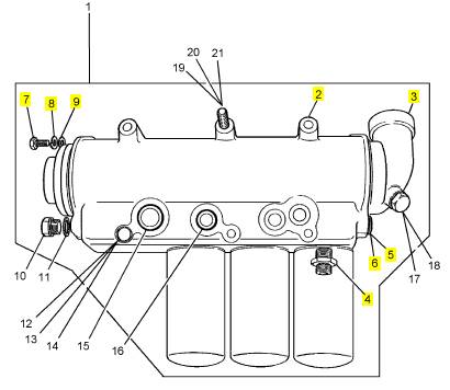
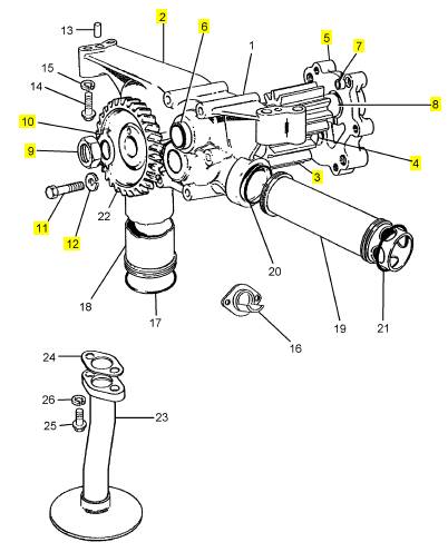
项目 零配件号码 最近的部分号码 描述
2 CV13139 1 CV13139 套
3 CV5620 1 CV5620 TUBESTACK
4 CV13136 3 CV13136 承接器
5 ST20134 1 ST20134 栓塞
6 ST49206 1 ST49206 垫圈
7 ST44424 2 ST44424 固定螺钉
8 2131 A012 2 2131 A012 垫圈
9 2131 A006 2 2131 A006 垫圈
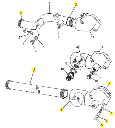
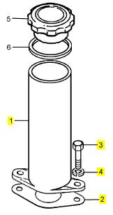
项目 零配件号码 最近的部分号码 描述
2 ST10614 4 ST10614 密封O型圈
3 CV18919 1 肘管
4 CV20335 1 CV20335 密封垫
5 ST43509 2 ST43509 螺拴
6 2134 A008 2 2134 A008 垫圈
7 2131 A008 2 2131 A008 垫圈
13 CV11762 1 CV11762 油管
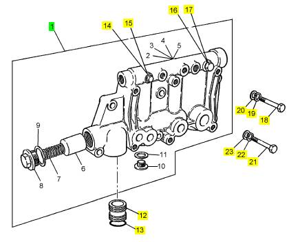
项目 零配件号码 最近的部分号码 描述
1 CV11804 1 CV11804 油泵
(1) CV11804R 1 CV11804R 油泵 -交换
13 OE4421 2 OE4421 销
14 ST43557 4 ST43557 螺拴
15 2134 A010 4 2134 A010 垫圈
16 CV13176 1 CV13176 栓塞
17 ST10619 2 ST10619 密封O型圈
18 CV12722 1 CV12722 油管
19 CV12723 1 CV12723 线桥
20 ST10615 1 ST10615 密封O型圈
21 ST10616 1 ST10616 密封O型圈
22 CV1274 1 CV1274 油泵传动机构
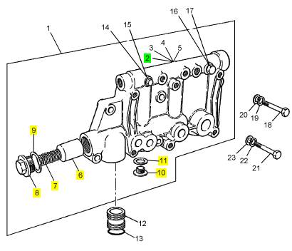
项目 零配件号码 最近的部分号码 描述
2 CV11802 1 CV11802 套
3 CV2279 1 CV2279 油泵传动机构
4 CV5340 1 CV5340 桥
5 CV11803 1 CV11803 盖
6 CV358 2 CV358 衬套
7 CV5671 1 CV5671 合钉
8 CV5339 1 CV5339 桥
9 ST44632 1 ST44632 锁紧螺母
10 CV334 1 CV334 定位键垫圈
11 ST43518 6 ST43518 螺拴
12 2134 A008 6 2134 A008 垫圈
项目 零配件号码 最近的部分号码 描述
1 CV7755/1 Z 1 CV7755/1 Z 阀
12 CV5122 2 CV5122 线桥
13 ST10615 8 ST10615 密封O型圈
14 ST46077 1 ST46077 栓塞
15 ST49852 1 ST49852 垫圈
16 ST46078 1 ST46078I 栓塞
17 ST49853 1 ST49853 垫圈
18 ST43655 3 ST43655 螺拴
19 ST43163 3 ST43163 垫圈
20 ST43059 3 ST43059 垫圈
21 ST43657 3 ST43657 螺拴
22 ST43163 3 ST43163 垫圈
23 ST43059 3 ST43059 垫圈
项目 零配件号码 最近的部分号码 描述
2 1 放泄阀
6 CV5121 1 CV5121 柱塞
7 CV1558 1 CV1558 弹簧
8 CV7719 1 CV7719 帽
9 ST49859 1 ST49859 垫圈
10 ST20106 2 ST20106 栓塞
11 ST49856 2 ST49856 垫圈
项目 零配件号码 最近的部分号码 描述
3 ST11412 3 ST11412 气门座圈
4 ST11421 1 ST11421 气门座圈
5 ST47474 6 ST47474 气门座圈
项目 零配件号码 最近的部分号码 描述
1 CV12724 1 CV12724 油填隙料
2 OE52128 1 OE52128 密封垫
3 ST43552 2 ST43552 螺拴
4 2134 A010 2 2134 A010 垫圈
5 If relevant, check that the bore for the cup plug in
the end of the rocker box is clean. Apply ’Loctite 542’
to a new cup plug and press the cup plug into the
rocker box until it is aligned prec isely with the wall.
6 For rocker boxes which do not have a cup plug in
the bore, insert the shaft into the bore from either end.
Ensure that the oil hole in the rocker shaft is facing
directly downward (toward the cylinder head). Fit the
rocker levers and the springs in the correct sequence
and, before the rocker shaft is fully into its correct
position, fit a new ’O’ ring in the groove around the
outer end of the rocker shaft.
7 Push carefully the rocker shaft through the bore
until the groove at the opposite end is just away from
the wall at the end of the rocker box. Fit the second
’O’ ring and press backward the shaft until the bolt
hole in the rocker shaft is aligned with the threaded
hole in the pedestal. Fit the bolt that holds the rocker
shaft, with a plain washer and a s pring washer, and
tighten it securely.
To ins pect and to correct 12-7
1 Remov e all of the grease and dirt from the
components by the use of an emulsifiable fluid, such
as ’Pavan’. Wash and dry each item before
inspection.
A
217
2 Inspect the rocker shaft for wear or damage around
the locations of the rocker levers. If wear is seen,
renew the shaft.
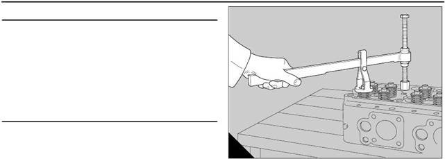
3 Fit each rocker lever onto the shaft and check the
clearance in the bush (page 35/A7) of the rocker
lever. If the clearance is excessive, make locally a
suitable tool as shown in figure (A) to press out the
bush. Make an accurate, temporary, mark on the
rocker lever to indicate the position of the small cutout
in the end of the bush and then press out the bush.
4 Check the bore of the rocker lever for deep
scratc hes or other damage.
36
Perkins Engines Company Limited
This document has been printed from SPI². Not for Resale
 12
12
5 If relevant, check that the bore for the cup plug in
the end of the rocker box is clean. Apply ’Loctite 542’
to a new cup plug and press the cup plug into the
rocker box until it is aligned precisely with the wall.
6 For rocker boxes which do not have a cup plug in
the bore, insert the shaft into the bore from either end.
Ensure that the oil hole in the rocker shaft is facing
directly downward (toward the cylinder head). Fit the
rocker levers and the springs in the correct sequenc e
and, before the rocker shaft is fully into its correct
position, fit a new ’O’ ring in the groove around the
outer end of the rocker shaft.
B
221
Perkins Engines Company Limited
37
This document has been printed from SPI². Not for Resale
 12
12
Tappet clearances
To check and to adjust
12-8
1 Remove the four rocker box covers, operation 12-4
or, if relevant, the four pedestal rocker cov ers,
operation 12-1.
Set the clearances for the bridge pieces and the
tappets as follows:
2 Turn the crankshaft in its normal direction of
rotation, anti-clockwise from the flywheel end, until
the A1 piston is at TDC on its compression stroke.
A
74
When the A1 piston is in this position, the exhaust
valves over the A6 cylinder are almost closed and the
inlet valves are just open. The valves for the A6
cylinder are then ’set’.
Caution: Ensure that no side load is put onto the
valve stems
Caution: When tappet clearances are checked and
adjusted on new engines, which have pedestal rocker
assemblies, it is necessary to check and adjust the
bridge pieces BEFORE the rocker assembly is fitted.
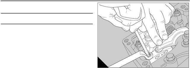
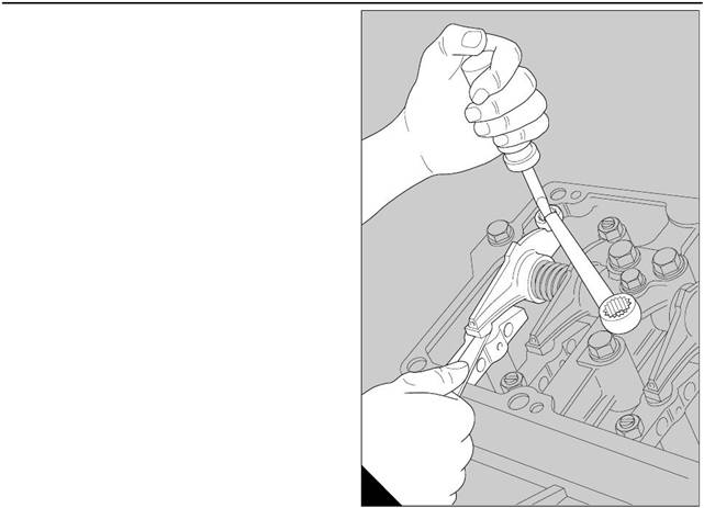
3 Turn anti-clockwise the adjustment screw and the
lock nut of each bridge piece to ensure that there is no
contact with the valve stem before it is adjusted. Start
with the number A1 inlet valves; apply pressure to the
tip of the rocker lever in contact with the button on the
bridge piece, or to the button itself if relevant, and turn
clockwise the adjustment s crew until it is just in
contact with the tip of the valve stem (A). Hold the
adjustment screw in this position with a screwdriver
and tighten lightly the lock nut.
4 For early engines, disengage the rock er lever from
its push rod and slide the rock er lever along the rocker
shaft to compress its spring. Tilt the rocker lever to
remove the bridge piece from its guide. Retain
securely the bridge piece in a vice fitted with soft
covers. Hold the adjustment screw in its position with
a screwdriver and tighten the lock nut to 40 Nm (30 lbf
ft). Replace the bridge piece on its guide. Similarly,
set the bridge piece of the A1 exhaust valves.
Caution: Use a torque wrench and an adaptor with a
ring spanner. The reading on the torque wrench must
be adjusted to compensate for the extra length which
is caused by the adaptor with the ring spanner.
5 If relevant for new engines, remove the bridge
piece from its guide. Retain s ecurely the bridge piece
in a vice fitted with soft covers. Hold the adjustment
screw in its position with a screwdriver and tighten the
lock nut to 40 Nm (30 lbf ft). Fit the bridge piece to its
guide. Similarly, set the bridge piece of the A1
exhaust v alves.
Caution: Use a torque wrench and an adaptor with a
ring spanner. The reading on the torque wrench must
be adjusted to compensate for the extra length which
is caused by the adaptor with the ring spanner.
38
Perkins Engines Company Limited
This document has been printed from SPI². Not for Resale
 12
12
6 For early engines, use the relevant feeler gauge
between the button of the bridge piece and the pad of
the rocker lever (A), to set the tappet clearance for the
A1 inlet valves to 0,40 mm (0.016 in). Tighten the loc k
nut of the adjustment screw to 40 Nm (30 lbf ft). For
new engines, from engine 8281 (6C27437/29), set
the tappet clearance for the A1 inlet valves to 0,20
mm (0.008 in).
7 For all engines, set also the tappet clearance of
the A1 exhaust valves to 0,50 mm (0.020 in) and
tighten the lock nut of the adjus tment screw to 40 Nm
(30 lbf ft). After the lock nuts have been tightened,
check again both tappet clearanc es and reset them, if
necessary, before the next set of tappets is adjusted.
To set the other tappet clearances in the correct
sequence, turn the cranks haft through 60° in its
normal direction of rotation for each set of valves. The
complete sequence is as follows:
8 'Set' the valves of the A6 cylinder. Then adjust/
check the tappet clearances for the A1 cylinder.
9 'Set' the valves of the B1 cylinder as for the A6
cy linder. Then adjust/check the tappet clearances for
the B6 cylinder.
10 'Set' the valves of the A3 cylinder. Then adjust/
check the tappet clearances for the A4 cylinder.
11 'Set' the valves of the B4 cylinder. Then adjust/
check the tappet clearances for the B3 cylinder.
A
73
12 'Set' the valves of the A5 cylinder. Then adjust/
check the tappet clearances for the A2 cylinder.
13 'Set' the valves of the B2 cylinder. Then adjust/
check the tappet clearances for the B5 cylinder.
14 'Set' the valves of the A1 cylinder. Then adjust/
check the tappet clearances for the A6 cylinder.
15 'Set' the valves of the B6 cylinder. Then adjust/
check the tappet clearances for the B1 cylinder.
16 'Set' the valves of the A4 cylinder. Then adjust/
check the tappet clearances for the A3 cylinder.
17 'Set' the valves of the B3 cylinder. Then adjust/
check the tappet clearances for the B4 cylinder.
18 'Set' the valves of the A2 cylinder. Then adjust/
check the tappet clearances for the A5 cylinder
19 'Set' the valves of the B5 cylinder. Then adjust/
check the tappet clearances for the B2 cylinder.
20 Fit the rocker box cover, operation 12-4 or, if
relevant, fit the pedestal rocker cover, operation 12-1.
Perkins Engines Company Limited
39
This document has been printed from SPI². Not for Resale
![]() 12
12
Cylinder head assembly
To remove and to fit
Special tools:
Lift adaptor, vertical - cylinder head, 21825 816
Slide hammer, 21825 849
Adaptor, blanking plugs, 21825 859
Lift adaptor - fuel injection pump, 21825 876
Guide studs - cylinder head, 21825 891
Guide studs, M15, cylinder head, 21825 921
12-9
To remove
A single cylinder head may be removed from the
engine and given an overhaul while the engine is still
connected to its relevant driven unit. In this situation,
ensure that the batteries are disconnected.
1 Disconnect the batteries.
2 Drain the coolant from the engine. Keep the
coolant in a clean container for subsequent use.
3 Disconnect the exhaust pipe from the elbow and
remove the elbow, and the exhaus t bellows if one is
fitted.
4 Remove the air ducts between the radiator, the air
filter and the turbocharger where necessary.
Disconnect and remove the air filter.
5 Disconnect and remove the coolant pipes from the
discharge side and the by-pass of the thermostat
housings.
6 Remov e the turbocharger from the engine,
operation 18-1.
7 Remov e the assembly of the exhaust manifold,
operation 18-4.
8 Remov e the high pressure fuel pipes of the fuel
injectors, the linkages to the governor for the engine
stop control and the engine speed control, the
assembly of the cross shaft and the engine stop
solenoid.
9 Disconnect, from the fuel injection pump and the
governor, all the pipes for the fuel supply, the spill fuel
and the lubricating oil.
40
Perkins Engines Company Limited
This document has been printed from SPI². Not for Resale
 10 Remove the guard of the auxiliary drive coupling
and remove the fuel injection pump, operation 20-11.
11 Remove the induction manifold, operation 18-5.
12 For early engines, remove the pipes for the
surplus fuel from the relevant cylinder head and then
remove the rocker box cover, operation 12-4.
13 Release the connections for surplus fuel from the
fuel injectors, release the clamps and remove the fuel
injectors, operation 20-7.
14 For new engines, disconnect the leak-off banjo
connections from the fuel injec tors and remove the
pedestal rocker cover, operation 12-1. Release the
clamps and remove the fuel injectors, operation 20-7.
15 For early engines, remove the rocker box,
operation 12-5. If relevant for new engines, remove
the pedestal rocker assembly, operation 12-2.
Remove and keep the six bridge pieces of the valves
and withdraw the six push rods.
16 Use the slide hammer, 21825 849, and the
adaptor, 21825 859, to withdraw the three blanking
plugs from the induction ports of the cylinder head.
17 For early engines, release the 22 nuts and the
three short bolts in the induction port, which retain the
cy linder head and remove the lift bracket if relevant.
12
18 For new engines, release two bolts, one at each
end of the three groups of four long bolts and fit two
guide studs, 21825 921. Release the remainder of
the 22 long bolts and the three short bolts in the
induction port, and remove the lift bracket if relevant.
Caution: The nuts or the bolts should be loosened
evenly and gradually from the centre to prevent local
stresses in the cylinder head.
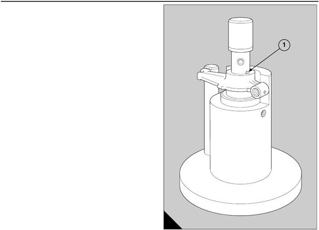
19 Use the lift adaptor (A3), 21825 816, to lift away
the cylinder head from the engine. Fit the lift adaptor
with the point of attachment for the hoist
approximately above the centre of gravity of the
cylinder head.
Caution: The lift adaptor, 21825 816, is designed for
use when the engine is in a build stand and the
cylinder heads are horizontal.
20 For early engines, remove the bobbin from its
location; for new engines, remove the sleeve (A1)
and the sealing ring (A2). Discard the cylinder head
gasket.
21 Put the cylinder head on a bench with a soft
surface, to av oid damage to the flame face.
A
340
Perkins Engines Company Limited
41
This document has been printed from SPI². Not for Resale
 12
12
To fit
1 If relevant, remove the four retainers which hold the
cylinder liners in the bank of cylinders. Check all the
joint faces for cleanliness and ensure that the location
dowels in the top face of the crankcase are
serviceable.
Caution: Use a brush and some clean engine
lubricating oil to lightly lubricate the threads and the
contact faces of the nuts, the bolts and, where
relevant, the s tuds which retain the cylinder heads.
Do not dip the fasteners in the lubricating oil.
2 For a cylinder head which is retained by studs
on an early engine, fit the bobbin, with a new ’O’ ring,
A
into its recess in the top face of the crankcase. Fit
carefully the new cy linder head gasket. Fit the
relevant lift adaptor to the cylinder head with the point
of attachment for the hoist approximately above the
centre of gravity of the cylinder head and lower the
cylinder head past the studs. Fit the lift bracket if
relevant, the plain washers and the nuts . Insert the
three short bolts which have shoulders through the
openings in the induction ports of the cylinder head
and into the threaded holes in the top face of the
cylinder bank.
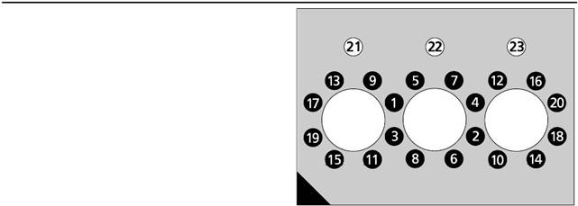
3 Tighten ev enly all the bolts and nuts in the
sequence shown (A) to a torque of 80 Nm (59 lbf ft).
Tighten all the bolts and nuts again, in the same
sequence, to a torque of 160 Nm (118 lbf ft), and then
to a final torque of 200 Nm (148 lbf ft). Do NOT tighten
the bolts in the induction ports (A21, A22 and A23)
beyond 200 Nm (148 lbf ft). Make a temporary mark
to mark the relationship of each nut to the cylinder
head. Tighten each nut, in the same sequence,
another quarter of a turn (90°). Do NOT turn the bolts
in the induction ports but c heck again that they are
tightened to a final torque of 200 Nm (148 lbf ft).
4 For a cylinder head which is retained by bolts
on a new engine, apply a small amount of locking
agent 'Loc tite 601' to the outer surface of the sleeve
for the lubricating oil, where it will be in contact with
the crankcase, and fit it in its hole in the top face of the
bank of cylinders. Do not allow the locking agent to
enter the passage for the oil and remove all the
surplus.
42
Perkins Engines Company Limited
This document has been printed from SPI². Not for Resale
5 Put the sealing ring around the sleeve and push the
sealing ring down to the flame face. Fit carefully the
new cylinder head gasket.
Caution: When there are exhaust bellows fitted to a
new engine, the support brackets of the exhaust
bellows must be fitted with the 156 mm long bolts.
6 Fit two guide studs, 21825 921, in the top face of
the crankcase. Use the relevant lift adaptor to lower
the cylinder head past the guide studs on to the flame
face. Fit the lift bracket if relevant, and the bolts in
their correct positions according to their lengths.
Remove the guide studs during this operation. Insert
the three bolts which have shoulders through the
openings in the induction ports of the cylinder head
and into the threaded holes in the top face of the
cy linder bank.
7 Tighten evenly all the bolts in the sequence shown
(page 42/A) to a torque of 80 Nm (59 lbf ft). Tighten all
the bolts again, in the same sequence, to a torque of
160 Nm (118 lbf ft), then again to 200 Nm (148 lbf ft).
Tighten only the long bolts to a final torque of 240 Nm
(177 lbf ft). Use a marker pen to mark the relationship
of each long bolt to the cylinder head. Tighten each
bolt, in the same sequence, another quarter of a turn
(90°). Do NOT turn the bolts in the induction ports but
check again that they are tightened to a final torque of
200 Nm (148 lbf ft).
8 Fit new 'O' rings to the three blank ing plugs of the
cy linder head and press each blanking plug into its
location in the induction ports.
9 In sequence, loosen the adjustment screw and the
lock nut of each bridge piece before it is fitted. Apply
engine lubricating oil to the guides of the bridge
pieces and fit the bridge pieces onto their guides with
the adjustment screws toward the outer edge of the
cylinder head.
10 Fit the rocker box, with a new joint, to the cylinder
head, operation 12-5.
11 Set the adjustments for the bridge pieces and the
tappet clearances, operation 12-8.
Caution: Ensure that no side load is put onto the
valve stems.
12 Fit the rocker box cover, operation 12-4.
13 Fit all components which were removed, in
reverse sequence to their removal. Check fits and
clearances where relevant.
12
Perkins Engines Company Limited
43
This document has been printed from SPI². Not for Resale
 12
12
To dismantle and to assemble
Special tools:
Drive handle, 21825 861
Replacer kit for cup plugs , 21825 866
Valve spring compressor, 21825 739
Adaptor, 21825 740
Stirrup, 21825 741
12-10
To dismantle
Check all cup plugs for signs of coolant leakage.
A
215
|
replacer kit, 21825 866, and the drive handle, 21825
861. Apply ’Loctite 575’ to new cup plugs before they
are fitted to the cylinder head. If the /8 BSP plug has
been removed because of leakage, clean the plug,
apply ’Loc tite 270’ to its threads, fit the plug and
tighten it to a torque of 28 Nm (21 lbf ft).
Put the cylinder head, flame face downward, on a
bench with a soft surface and remove the valves by
use of the valve spring compressor, 21825 739, with
adaptors 21825 740 and 21825 741. Use the
procedure whic h follows:
1 Fit the adaptor, 21825 740, into a suitable bolt hole
for the rocker box.
2 Fit the compressor tool stud into the adaptor, finger-
tight, and tighten the lock nut.
3 Set the arm of the valve spring compress or at a
suitable height on the stud by use of the two lock nuts.
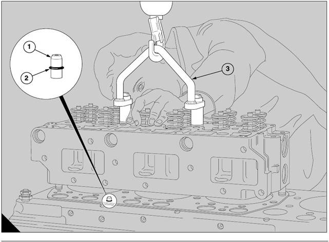
4 Set the stirrup, 21825 741, on the arm, directly over
one of the valve assemblies (A).
5 Compress the valve spring and lift out the collets
followed by the upper spring seat or rotator, then the
spring and the lower s pring s eat.
6 Move the compressor tool, as necessary, and
repeat the operation until all the valve assemblies
have been removed. To ensure that the valves are
fitted to the correct positions during the assembly of
the cylinder head, the number of the cylinder and the
position of each valve should be etched above the
collet groove on the valve stem. Valves must not be
stamped or marked with a centre punch because
cracks may occur.
7 Turn the cylinder head onto its side and withdraw
all of the valves
To assemble
Apply engine oil to the valve stems, fit each valve into
its correct guide, according to the marking which is
etched on the stem. Lower carefully the assembly of
the cylinder head on to the bench with the flame face
downward, then fit the lower spring seat, spring and
spring retainer or valve rotator, as relevant, over the
valve stem.
Compress each spring assembly and fit the collets
into the collet grooves in the valve stems. Release,
carefully, the valve spring compressor, check that the
collets remain in their correct location, and then
proceed to the next unit.
44
Perkins Engines Company Limited
This document has been printed from SPI². Not for Resale