 English
 Espaol
 Franais
 阿拉伯
阿拉伯 中文
中文 Deutsch
 Italiano
 Português
 日本
日本 韩国
韩国 български
 hrvatski
 esky
esky Dansk
Dansk Nederlands
 suomi
suomi Ελληνικ
 印度
印度 norsk
norsk Polski
 Roman
Roman русский
 Svenska
Perkins3012柴油发动机威尔逊P850E柴油发电机配件CV72010缸套供应商,Perkins3012柴油发动机威尔逊P850E柴油发电机配件CV72010缸套技术价格规格咨询服务,Perkins3012柴油发动机威尔逊P850E柴油发电机配件CV72010缸套零配件供应,Perkins3012柴油发动机威尔逊P850E柴油发电机配件CV72010缸套售后服务中心,Perkins3012柴油发动机威尔逊P850E柴油发电机配件CV72010缸套,Perkins3012柴油发动机威尔逊P850E柴油发电机配件CV72010缸套详细的技术参数,

产品中心
Perkins3012柴油发动机威尔逊P850E柴油发电机配件CV72010缸套
详细描述
项目 零配件号码 最近的部分号码 描述
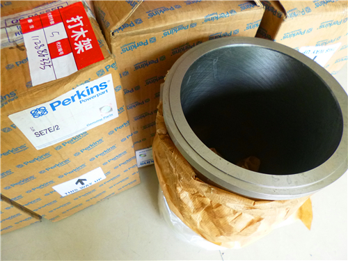
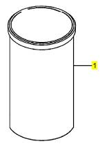
1 CV72010 12 CV72010 缸套
1 CV19912 12 CV72010 缸套
(1) CV11401 12 CV11401 缸套
(1) CV11402 12 CV11402 缸套 -特大号
项目 零配件号码 最近的部分号码 描述
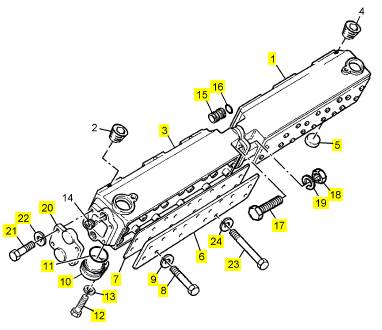
1 CV12310 2 CV12310 岐管
3 CV12310 2 CV12310 岐管
5 ST43325 2 ST43325 栓塞
6 CV8927 4 CV8927 板
7 CV20227 4 CV20227 密封垫
8 ST44456 16 ST44456 螺拴
9 ST43161 16 2134 A010 弹簧塾圈
10 CV13396 2 CV13396 栓塞
11 ST10935 2 ST10935 封闭砂条
12 ST44441 2 2314 C045 固定螺钉
13 ST43160 2 2134 A008 垫圈
15 CV12311 12 CV12311 线桥
16 ST10890 24 ST10890 封闭砂条
17 ST44458 8 2314 C053 固定螺钉
18 ST44606 6 2318 A209 公制的螺帽
19 ST43161 8 2134 A010 弹簧塾圈
20 CV12560 2 CV12560 帽
21 ST43551 8 ST43551 螺拴
22 ST43161 8 2134 A010 弹簧塾圈
23 ST43574 48 ST43574 螺拴
24 ST43161 48 2134 A010 弹簧塾圈
项目 零配件号码 最近的部分号码 描述
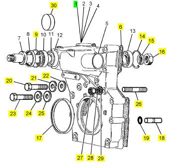
1 CV9278/1 Z 1 CV9278/1 Z 壳
6 CV20362 1 CV20362 密封垫
9 ST49007 1 ST49007 CIRCLIP
14 ST49007 1 ST49007 CIRCLIP
15 CV5533 1 CV5533 垫圈
16 CV5324 1 CV5324 螺帽
17 CV17402 1 CV17402 密封 -前面端油
18 CV1305 2 CV1305 合钉
19 CV1306 2 CV1306 密封O型圈
20 ST43712 5 ST43712 螺拴
21 ST43164 5 ST43164 垫圈
22 2131 A016 5 2131 A016 垫圈
23 ST43515 9 ST43515 螺拴
24 2134 A008 9 2134 A008 垫圈
25 2131 A008 9 2131 A008 垫圈
26 CV7617 1 CV7617 图钉
27 2318 A222 1 2318 A222 螺帽
28 ST43164 2 ST43164 垫圈
29 2131 A016 2 2131 A016 垫圈
30 CV14151 2 CV14151 栓塞
项目 零配件号码 最近的部分号码 描述
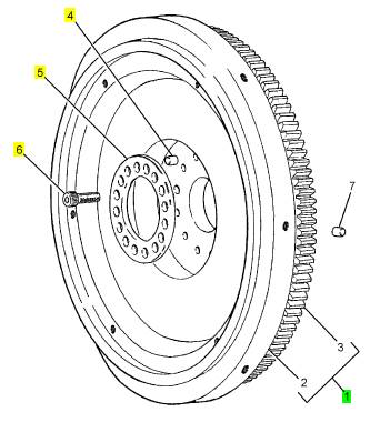
1 CV14445/1 1 CV14445/1 飞轮组合
4 CV6460 1 CV6460 销
5 CV2481 1 CV2481 圈
6 ST46709 16 ST46709 CAPSCREW
项目 零配件号码 最近的部分号码 描述
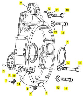
1 CV14092 1 飞轮壳
2 CV20222 1 CV20222 密封垫
3 CV17404 1 CV17404 密封 -背面端油
4 ST46079 1 ST46079 栓塞
5 ST49891 1 ST49891 垫圈
6 CV6461 2 CV6461 销
7 OE25649 1 OE25649 栓塞
8 ST49853 1 ST49853 垫圈
9 ST20704 2 ST20704 栓塞
10 ST43652 1 ST43652 螺拴
11 ST43163 1 ST43163 垫圈
12 ST43603 8 ST43603 公制的螺拴
13 2134 A012 8 2134 A012 垫圈
14 ST43602 2 ST43602 螺拴
15 2134 A012 2 2134 A012 垫圈
16 ST43620 2 ST43620 螺拴
17 2134 A012 2 2134 A012 垫圈
18 ST43605 9 ST43605 螺拴
19 2134 A012 9 2134 A012 垫圈
项目 零配件号码 最近的部分号码 描述
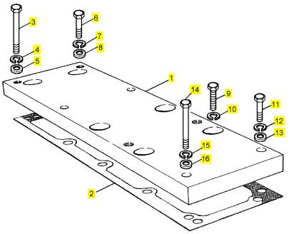
1 CV1499 1 CV1499 架设板
2 CV19541 1 CV19541 密封垫
3 ST43580 2 ST43580 螺拴
4 2134 A010 2 2134 A010 垫圈
5 2131 A010 2 2131 A010 垫圈
6 ST43552 2 ST43552 螺拴
7 2134 A010 2 2134 A010 垫圈
8 2131 A010 2 2131 A010 垫圈
9 ST44456 6 ST44456 螺拴
10 2134 A010 6 2134 A010 垫圈
11 ST43557 2 ST43557 螺拴
12 2134 A010 2 2134 A010 垫圈
13 2131 A010 2 2131 A010 垫圈
14 ST43583 2 ST43583 螺拴
15 2134 A010 2 2134 A010 垫圈
16 2131 A010 2 2131 A010 垫圈
项目 零配件号码 最近的部分号码 描述
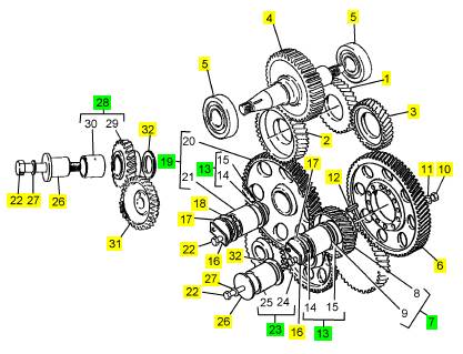
1 1 凸轮轴传动机构
2 1 凸轮轴传动机构
3 1 凸轮轴传动机构
4 1 高压油泵传动机构
5 2 推拔瓦
6 CV70056 1 CV70056 混合传动机构
6 CV7866 1 CV70056 混合传动机构
7 CV7868 1 CV7868Z 混合传动机构
10 CV17071 12 CV17071 固定螺钉
11 ST43056 12 2131 A008 垫圈
12 ST45778 1 ST45778 弹簧销
13 CV13003 2 CV13003Z 车桥
16 CV8666 2 CV8666 锁定板
17 CV11604 2 CV11604 推力板
18 CV430 4 CV430 止推片
19 CV1412 1 CV1412Z 惰轮传动机构
22 CV12174 6 CV12174 螺拴
23 CV1414 1 CV1414Z 惰轮传动机构
26 CV329 2 CV329 车桥
27 ST43058 2 2131 A012 垫圈
28 CV1415 1 CV1415 惰轮传动机构
31 1 油泵传动机构
32 CV1381 2 CV1381 止推片
项目 零配件号码 最近的部分号码 描述
14 CV12820 1 CV12820 车桥
15 CV2491 1 CV2491 间隔器
Clean all of the components; use a cleaning fluid
which can be diluted with water and refer to section 10
for relevant information. To remove heavy carbon
deposits from most components: soak them in
solutions of ’Maxan’ or ’Ardrox 667’.
Caution: Do not use the ’Maxan’ or ’Ardrox’
processes on the valve springs or the surface finish
will be damaged.
If cup plugs were removed, before the cylinder head
was cleaned, they must be renewed before the
cy linder head is given a test under pressure. Apply
’Loc tite 575’ to the new cup plugs and insert them into
their correct locations in the cylinder head. Us e the
relevant kit of remov al/replacer tools for the cup
plugs.
Make, locally, enough seals to close all of the
openings for coolant and fit them to the cylinder head.
Connect a pipe from a supply of air to the coolant
galleries. Apply air at a pressure of 207 kN/m² (30 lbf/
in²).
Caution: Do NOT exceed 207 kN/m² (30 lbf/in²) as
damage may be caused.
Put the cylinder head in a tank of water which is at a
temperature of 60°C (140°F) and inspect for bubbles
from around all the cup plugs and injector sleeves.
Renew plugs or sleeves which are not fully sealed.
Remove the seals from the openings for coolant.
Inspect the flame face for s igns of damage. If
necessary, the face may be reconditioned by surface
grinding, in four stages, to a maximum of 0,51 mm
(0.020 in). Information about work done must be
etched on an area of the flame face which is not under
the gasket of the cylinder head.
Caution: When a cylinder head flame face has been
machined, the valve seats must be re-cut to maintain
the correct distance between the valve faces and the
flame face of the cylinder head. See fits and
clearances on page 60.
Perkins Engines Company Limited
45
This document has been printed from SPI². Not for Resale
 12
12
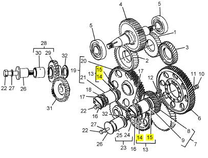
To correct a valve seat
Special tools:
Valve seat tool, 21825 841
Valve seat cutter, 21825 842
12-12
It is recommended that all the valve guides are
inspected, and renewed as necessary, before the
work is begun on the v alve seat inserts. Ensure that
the bores of the guides are within the limits given at
the end of this section.
1 Inspect the inserts for erosion and cracks. If it is
necessary to correct the inserts, lightly lap the faces
of the valve seats and their relevant valves. To correct
the faces of more badly damaged valve seats, use the
valve seat tool, 21825 841, and the cutter, 21825 842,
together with the relevant pilot. To use the tool, fit the
guide (A) and proceed as s hown (B). Ensure that the
cutter is correct for the angle of the v alve seat, which
is giv en on page 60. The surface finish of the valve
seat will be improved if a compressed air supply is
used to remove debris during this operation.
Warning! Ensure that eye protection is used during
the above operation.
Caution: During the correction of a valve seat it is
important to remove only the minimum amount of
material.
2 After the inspection and correction of a valve seat
and the relevant valve, fit the valve into the guide and
check the depth of the head of the valve below the
flame face. If the depth is more than the limits given
on page 60 use a new valve to check again. If the
depth is then within acceptable limits, the new valve
must be fitted to the valve seat when the cy linder
head is assembled.
3 To ensure that the valve is fitted in its correc t
position, the number of the cylinder and the position
of the valve must be etched above the collet groove
on the valve stem. Valves must not be stamped or
A
B
222
223
marked with a centre punch, because crack s may
occur.
If the depth still exceeds the acceptable limits, a new
valve seat insert must be fitted.
46
Perkins Engines Company Limited
This document has been printed from SPI². Not for Resale
 12
12
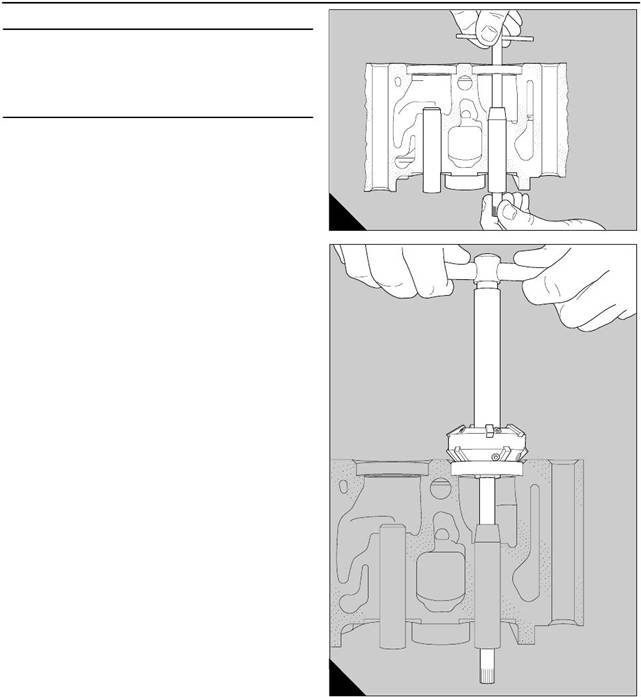
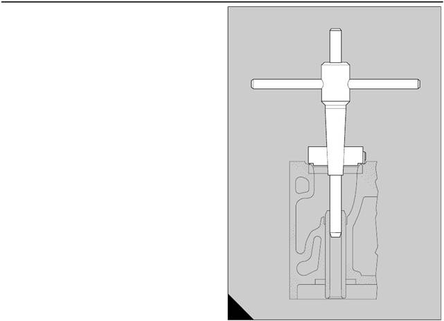
To remove a valve seat insert
Special tools:
Holder, 21825 892
12-13
Cutter for the removal of valve seats, 21825 893
Expendable extractor, 21825 896
Caution: Before a valve seat insert for an exhaust
valve can be removed, the edge of the casting of the
cy linder head, which is rolled over the insert, must be
cut away (A). A special cutter, 21825 893, and holder,
21825 892, are available for this purpose.
1 If the relevant valve guide has not been removed,
and its bore is within the acceptable limits, turn the
cy linder head onto its side and slide the expendable
extractor, 21825 896, into the valve guide, until the
head is in contac t with the valve seat insert.
2 Weld electrically, at two or three equally spaced
positions around the circumferenc e, the expendable
extractor to the valve seat insert. Make the welds no
larger than is necessary in order to prevent damage
to the cylinder head.
3 Use a soft faced hammer on the end of the stem of
the expendable extractor to remove the old valve s eat
insert from its recess (B).
The expendable extractor may be used again if the
welds and the old valve seat insert are removed and
the head is ground lightly to eliminate the protrusions.
A
224
B
225
Perkins Engines Company Limited
47
This document has been printed from SPI². Not for Resale
 12
12
|
|
|
|
is given below:
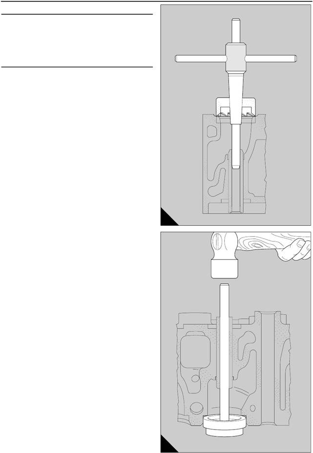
1 Fasten securely the cylinder head on a milling
machine, and use a slot drill of approximately 10 mm
seat insert (A3). The depth of the slots should be 0,50
mm (0.020 in) less than the depth of the valve seat
insert. The minimum depth of the insert is 7,95 mm
(0.313 in). The slots should be apart by
Machine the slot to within 0,5 mm (0.020 in) of the
outside diameter of the insert.
2 Use a flat chisel, at the point which is indicated by
the arrow (A2) and in the direction of the opening in
the insert, to break the insert. Do not damage the
recess during this operation.
3 Remov e the insert and check that the recess is
clean and that there is no damage.
To fit a valve seat insert 12-14
Special tools:
Valve seat tool, 21825 841
Valve seat cutter, 21825 842
Drive handle, 21825 861
Tool to insert valve seat, 21825 867
Holder for rolling tool, 21825 892
Rolling tool, 21825 894
A
34
1 Valve seat inserts are available in two sizes,
oversize and standard. The oversize inserts are 0,05
mm (0.002 in) larger on the outer diameter. If an
oversize insert is to be fitted, ensure that it has the
correct part number: CV 14128 for an inlet seat or OE
47574 for an exhaust seat. Check als o that the wall
of the recess in the cylinder head will maintain the
correct interference fit, as given on page 60.
2 Cool the valve seat insert in liquid nitrogen to -35°C
(-31° F). Use the special tool, 21825 867, (B1) and the
B
226
handle, 21825 861 (B2), to fit the relevant insert into
its rec ess as rapidly as possible.
3 Use a 0,04 mm (0.0015 in) feeler gauge to c heck
that the bottom of the new insert is in full contact with
the bottom of the recess.
If a new v alve seat insert has been fitted for an
exhaust valve, the edge of the casting of the cylinder
head must be rolled over the chamfer which is around
the circumference of the insert. Proceed as follows :
4 Fasten securely the cylinder head on a s uitable drill
machine with the flame face in the upper position and
fit the rolling tool, 21825 894, and holder, 21825 892,
to the machine.
48
Perkins Engines Company Limited
This document has been printed from SPI². Not for Resale
![]() 12
12
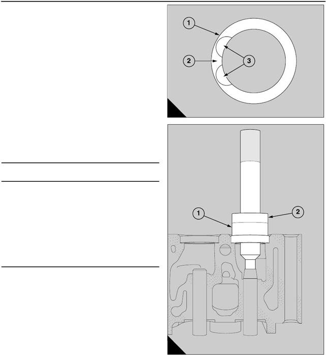
5 Apply clean engine lubricating oil to the rollers, to
the face at the end of the tool and to the c ounterbore
in the cylinder head.
6 Insert the rolling tool in the valve guide and turn
slowly the rolling tool. Apply enough pressure to
spread the material of the cylinder head over the
chamfer of the valve seat insert. Ensure that the face
at the end of the tool is suitably lubricated before the
face at the end of the tool is in contact with the top
face of the insert (A). When this occurs, the cylinder
head is fully rolled over the insert, and the tool can be
removed.
7 Use the valve seat cutter, 21825 842, and the
relevant pilot, to machine to the correct angle, the
seats which have been renewed. Ensure that the
cutter is correct for the angle of the valve seat, which
is given on page 60. Lap the valves to the seats.
Clean thoroughly the area around the valv es and the
seats and use engineer’s blue to check that the fac es
of the valves are in full contact across and around the
faces of the valve seats.
8 Fit the valves in their relevant seats and use a
straight edge and a feeler gauge to check that the
clearances between the heads of the valves and the
flame face are within the limits given on page 60. If a
clearance is excessive, a new valve must be fitted.
The number of the cylinder and the position of the
valve should be etched above the collet groove on the
A
227
valve stem. Valves must not be stamped or marked
with a centre punch, because cracks may occur.
To inspect the valve guides 12-15
Check the clearance of each valve stem in its guide.
This must be within the limits given on page 59. If the
clearance is excessive, use a new valve to check
again. If the c learance is still excessive, a new valve
guide must be fitted.
Perkins Engines Company Limited
49
This document has been printed from SPI². Not for Resale
 12
12
To renew a valve guide
Special tools:
Reamer for exhaust valve guides, 21825 755
Reamer for inlet valve guides, 21825 756
Valve seat tool, 21825 841
Valve seat cutter, 21825 842
Remover for inlet valv e guides, 21825 885
12-16
Remover for exhaust valve guides, 21825 886
Replacer for inlet valve guides, 21825 887
Replacer for ex haust valv e guides, 21825 888
Use the extractors: 21825 885 (inlet valves) or 21825
886 (exhaust valves), and the replacer tools 21825
887 (inlet valves) or 21825 888 (exhaust valves),
together with a suitable press.
1 Use the relevant extractors to press out the valve
guides that need to be renewed. Check the bores in
the cylinder head for wear or damage. See SRS 135
for instructions to correct worn bores.
2 Apply clean lubricating oil to the new guide before
it is inserted in the top end of the bore.
Caution: The guides for the inlet valves must be
inserted with the tapered end downward. The guides
for the exhaust valves must be inserted with the
internal chamfer, which is at one end of the bore, at
the top.
3 Fit the relevant replacer tool onto the guide and
press the guide in until the replacer tool is in c ontact
with the cylinder head (A). This will give the correct
protrusions of 12,8 mm (0.50 in) for the guides of the
inlet valves and 17,85 mm (0.70 in) for the guides of
the exhaust valves.
Caution: If liquid air is available, it may be help if the
new valve guide is cooled immediately before it is
fitted.
4 Use the correct reamer to ream the new valve guide
(B) and check the bore with the relevant plug gauge.
Use the reamer 21825 756 for inlet valve guides and
21825 755 for exhaust valve guides.
If new valve guides have been fitted, the relevant
valve seat insert must be corrected. Use the special
tool, 21825 842, to ensure concentricity.
A
230
B
231
50
Perkins Engines Company Limited
This document has been printed from SPI². Not for Resale
 12
12
|
12-17
Inspect the bridge pieces and the adjustment screws
for wear. Use a new guide as a gauge to c heck the
bores in the bridge pieces. Similarly, use a new
bridge piece to check the guides. Renew
components which have excessive wear.
|
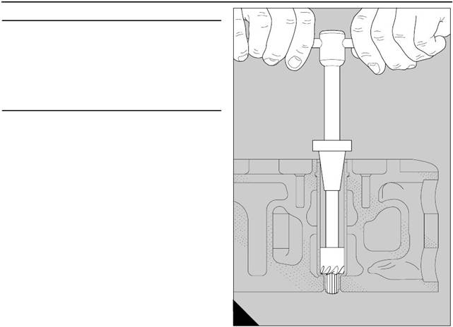
Special tools:
Extractor for valve bridge guides, 21825 889
12-18
Depth plate for valve bridge guides, 21825 890
Use the extractor, 21825 889, to withdraw a worn
guide from its bore in the cylinder head (A). Clean
thoroughly the bore.
Apply ’Loctite 648’ to the area of the new guide which
is an interference fit in the cylinder head and use a
press to insert the guide into the c ylinder head. To
obtain the correct protrusion, fit the depth plate,
21825 890, ov er the guide and press the guide into its
bore until the top face is aligned precisely with the top
face of the depth plate (B).
A
232
B
233
Perkins Engines Company Limited
51
This document has been printed from SPI². Not for Resale
 12
12
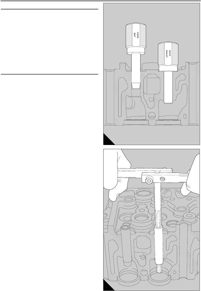
To recondition a fuel injector sleeve
Special tools:
12-19
Tool holder for face cutter and reamer, 21825 765
Face cutter, 21825 767
Reamer, 21825 768
Service kit for fuel injector sleeves, 21825 915
Caution:
The fuel injector sleeves may be renewed
without the removal of the cylinder head from the
engine. In this situation, the coolant must be drained
until the level is below the cylinder head and the
piston, which is below the faulty fuel injector sleeve,
must be moved to BDC.
1 Use the integral face cutter and reamer to remove
deposits of carbon and to correct the face of the seat,
or the bore at the smaller internal diameter of the
injector sleeve (A). If the work is done without the
removal of the cylinder head from the engine, the
cutter and the reamer must be given a full application
of grease to retain the particles of the carbon and the
debris.
Caution: When the face cutter is used, remove only
the minimum material that is necessary to correct the
seat. The maximum permissible depth of the seat
from the top face of the cylinder head is 104,25 mm
A
237
(4.104 in).
52
Perkins Engines Company Limited
This document has been printed from SPI². Not for Resale