 English
 Espaol
 Franais
 阿拉伯
阿拉伯 中文
中文 Deutsch
 Italiano
 Português
 日本
日本 韩国
韩国 български
 hrvatski
 esky
esky Dansk
Dansk Nederlands
 suomi
suomi Ελληνικ
 印度
印度 norsk
norsk Polski
 Roman
Roman русский
 Svenska
Perkins3012柴油发动机威尔逊P850E柴油发电机配件供应商,Perkins3012柴油发动机威尔逊P850E柴油发电机配件技术价格规格咨询服务,Perkins3012柴油发动机威尔逊P850E柴油发电机配件零配件供应,Perkins3012柴油发动机威尔逊P850E柴油发电机配件售后服务中心,Perkins3012柴油发动机威尔逊P850E柴油发电机配件,Perkins3012柴油发动机威尔逊P850E柴油发电机配件详细的技术参数,

产品中心
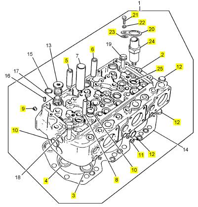
Perkins3012柴油发动机威尔逊P850E柴油发电机配件CV24952/3汽缸盖
详细描述
项目 零配件号码 最近的部分号码 描述
1 CV19682/2 4 CV24952/3 汽缸盖组合
13 OE43640 12 OE43640 栓塞
14 CV13202 4 CV13202 密封垫 - 汽缸盖
15 ST10603 12 ST10603 密封O型圈
16 ST45778 8 ST45778 弹簧销
17 CV1472 12 CV1472 固定螺钉
18 CV12855 35 CV69480 固定螺钉
19 CV12853 40 CV69478 固定螺钉
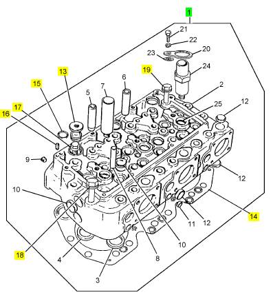
项目 零配件号码 最近的部分号码 描述
2 1 汽缸盖
3 CV7699 6 CV20814 气门座圈
3 CV14128 1 CV21069 气门座圈
4 OE43633 6 CV20815 气门座圈
4 OE47574 1 CV21070 气门座圈
5 OE47572 6 OE47572 气门导管
6 OE47573 6 OE47573 气门导管
8 OE43636 6 OE43636 气门导管
9 ST20701 1 ST20701 栓塞
10 ST43322 9 ST43322 栓塞
11 ST43309 3 ST43309 栓塞
12 ST43317 10 ST43317 栓塞
20 CV19679 3 CV19679 锁定板
21 2314 J003 3 2314 J003 螺旋
22 ST43161 3 2134 A010 弹簧塾圈
23 ST43057 3 2131 A010 垫圈
24 CV19681 3 CV19681 套筒
25 ST10609 3 ST10609 密封O型圈
To renew a fuel injector sleeve
Special tools:
12-20
Remover tool for fuel injector sleeves, 21825 771
Tap, 21825 773
Expander tool for fuel injector sleeves, 21825 776
Ball type expander tool, 21825 883
A fuel injec tor sleeve which is outside the limit, or has
been damaged, or which leaks from the expanded
joints and c annot be corrected by further expansion of
the ends of the fuel injector sleeves, must be renewed
in accordance with the instructions given below.
Caution: The fuel injector sleeves may be renewed
without the removal of the cylinder head from the
engine. In this situation, the coolant must be drained
until the level is below the cylinder head, and the
piston which is below the faulty fuel injector sleeve
must be moved to BDC.
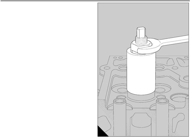
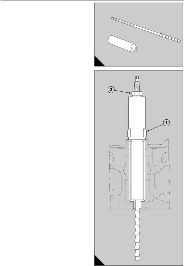
1 Use the tap, 21825 773, to make a thread in the fuel
injector sleeve to a minimum depth of 25 mm (one
inch)(A). If the work is done without the removal of the
cy linder head from the engine, push some clean rag
down the larger bore to prevent the possible entry of
debris into the cylinder of the engine. The tap should
be given a full application of grease to retain the
particles of copper debris.
2 Move up the nut of the remover tool, 21825 771, to
the top of its thread and fit fully the stud into the thread
in the fuel injector sleeve (B).
A
238
B
239
Perkins Engines Company Limited
53
This document has been printed from SPI². Not for Resale
 12
12
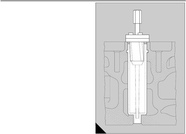
3 Tighten down the nut against the thrust face of the
tool and withdraw the fuel injector sleeve (A). Extra
force is necess ary to break the top seal where the
sleeve has been rolled into the groove in the cylinder
head.
4 Clean thoroughly the bores in the cylinder head and
also the groove for the expansion of the fuel injector
sleeve.
A
240
54
Perkins Engines Company Limited
This document has been printed from SPI². Not for Resale
 12
12
If the c ylinder head has been removed from the
engine, put it on parallel supports under a press, with
the flame face downward. The supports must be
deep enough to ensure that there is a clearance of
approximately 150 mm (6 in).
5 Dismantle the tool, 21825 883, and insert the
section with the ball type expander through the fuel
injector sleeve as shown (A). Assemble the tool and
lubricate with grease the end with the ball type
expander. Install the fuel injector sleeve in the bores
of the cylinder, use the clamp of a fuel injec tor (B1) to
fasten the assembly to the cylinder head and tighten
the cap screw to 60 Nm (44 lbf ft) to ensure that the
fuel injector sleeve is press ed fully into its correct
location.
6 Turn the nut (B2) at the top of the tool and pull up
the ball type expander through the fuel injector
sleeve. This action causes the expansion of the bore
at the smaller internal diameter.
A
241
B
242
Perkins Engines Company Limited
55
This document has been printed from SPI². Not for Resale
 12
12
When the expansion of the smaller bore is complete,
the expansion at the top of the fuel injector sleeve
should be done by use of the expander tool, 21825
776, which rolls the copper of the fuel injector sleeve
into the groove in the cylinder head.
7 Insert the housing for the expander rollers into the
injector sleeve until the shoulder of the housing is in
contact with the top face of the cylinder head.
8 Slide the tapered shaft through the housing of the
rollers and use a suitable socket type spanner and a
tee handle to turn the shaft while a constant pressure
is applied downward to the end of the shaft.
9 Continue the operation until the shaft is difficult to
turn when it is approximately at the position shown
(A). The tool can then be removed; there is not
usually a requirement for the shaft to go deeper.
A
243
56
Perkins Engines Company Limited
This document has been printed from SPI². Not for Resale
![]()
![]() Valves, valve springs and valve rotators
Valves, valve springs and valve rotators
To remove and to fit 12-21
Special tools:
Valve spring compressor, 21825 739
Adaptor, 21825 740
Stirrup, 21825 741
To remove
1 Remove the cylinder head, operation 12-9.
2 Dismantle the cylinder head, operation 12-10 and
keep together the components of each assembly of
the valves .
3 Ensure that the identification of the position of each
valve is maintained, paragraph 5 of operation 12-10.
To fit
1 Ens ure that each valve is fitted into its correct guide
according to its identification.
2 Assemble the valves, valve springs, seats for the
springs and the valve rotators in the cylinder head,
operation 12-10.
The valve rotators are fitted only on the exhaust
valves. The valve spring caps are fitted only on the
inlet valves.
3 Fit the cylinder head, operation 12-9.
To inspect and to correct 12-22
1 Clean thoroughly each valve and inspect visually
for cracks, for pitting or for other damage on the head
of the valve. Check for wear on the valve stems, the
collet grooves and the valve tips. The heads of the
valves should also be checked for cracks by the us e
of the dye penetrant process.
2 Use a s traight edge and a feeler gauge to check
that the top face of the head of the valve is not dished.
Discard the valve if the clearance exceeds 0,13 mm
(0.005 in) at the centre of the valve.
3 Clean thoroughly the area around the valve seat
and fit, one at a time, each valve to its correct position
in the cylinder head acc ording to the number of the
cy linder and the position of the valve, which is etched
above the collet groove on the valve stem.
12
Use engineer’s blue to check that the face of the valve
is in full contact across and around the face of the
valve seat. Lap the valve to the valve seat if
necessary. Clean thoroughly the area around the
valves and the seats and again use engineer’s blue to
check that the faces of the valves are in full contact
across and around the faces of the valve seats.
4 Use a s traight edge and a feeler gauge to check
that the clearance between the head of the valve and
the flame face is within the limits given on page 60. If
the clearance is excessive, a new valve must be
fitted. If, after a new valve has been fitted, the
clearance is still excessive, a new valve seat insert
must be fitted.
5 Insufficient clearance can be corrected by the use of
the valve seat cutter, 21825 841, and its relevant pilot,
to machine the seat of the insert, operation 12-12.
Ensure that the cutter is correct for the angle of the
valve seat, which is given on page 60. Lap the valves
to the seats. Clean thoroughly the area around the
valves and the seats and use engineer’s blue to check
that the faces of the valves are in full contact across
and around the faces of the valve seats.
6 If new valves are fitted, the number of the cylinder
and the position of the valve should be etched above
the collet groove on the valve stem.
7 Fit the new valve in the v alve seat and check that
the face of the valve is in full contact across and
around the face of the v alve seat. Check also the
clearance between the head of the valve and the
flame face as given above.
8 Check each valve spring for wear, damage and
corrosion. Measure the free length and the length
under a load, as given on page 60. Discard all springs
which are unserviceable.
9 Renew the springs as a set of two below their
relevant bridge piece. Old and new springs must not
be mixed on a set of two valves as this can cause
wear to the valve bridge and the v alve guide.
Caution: Fit new valve springs at every complete
engine overhaul. Ensure that the new valve springs
are correc t for the engine before they are fitted.
10 Check the valve rotators for cracks and other
damage, and ensure that each c omponent can rotate
freely within the assembly.
11 Inspect the tips of the exhaust valve stems. If the
type of wear indicates that a valve has not rotated
correctly, the valve rotator of the relevant valve must
be renewed.
Perkins Engines Company Limited
57
This document has been printed from SPI². Not for Resale
![]() 12
12
Push rods
To remove and to fit
To remove
12-23
1 Remov e the relevant rocker box cover, operation
12-1 or operation 12-4.
2 Rotate the engine until the tappet of the relevant
push rod is on the heel of its cam, loosen fully the
adjustment s crew of the rocker lever. Disengage the
rocker lever from the push rod and slide the rocker
lever along the rocker shaft to compress its spring.
Hold the rocker lever in its new position and lift out the
push rod.
3 If some, or all, of the push rods are to be removed
when the engine is overhauled, remove the rocker
boxes, operation 12-5, or pedestal rocker assemblies,
operation 12-2.
To fit
1 Fit each push rod in the reverse sequence to the
removal.
2 Set the tappets, operation 12-8.
3 Fit the relevant rocker box cover, operation 12-1 or
operation 12-4.
To inspect 12-24
1 Inspect the ends of each push rod for wear and
damage, and check each rod for deflection. A push
rod which has a run-out of more than 0,2 mm (0.008
in) along its overall length must be renewed.
58
Perkins Engines Company Limited
This document has been printed from SPI². Not for Resale
 Fits and clearances - Cylinder heads, rocker assemblies and valves
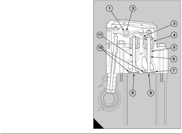
Bridge pieces on guides (A3)
12
Bore of bridge piece . . . . . . . . . . . . . . . . . . . . . . . . . . . . . . . . . . . 12,755 to 12,780 mm (0.5021 to 0.5031 in)
Diameter of guide . . . . . . . . . . . . . . . . . . . . . . . . . . . . . . . . . . . . . 12,728 to 12,739 mm (0.5011 to 0.5015 in)
Clearance (new) . . . . . . . . . . . . . . . . . . . . . . . . . . . . . . . . . . . . . . . . 0,016 to 0,052 mm (0.0006 to 0.0020 in)
Permissible worn clearance. . . . . . . . . . . . . . . . . . . . . . . . . . . . . . . . . . . . . . . . . . . . . . . . . 0,10 mm (0.004 in)
Valve springs (A4)
Free length (nominal) . . . . . . . . . . . . . . . . . . . . . . . . . . . . . . . . . . . . . . . . . . . . . . . . . . . 47,066 mm (1.853 in)
Permissible worn length . . . . . . . . . . . . . . . . . . . . . . . . . . . . . . . . . . . . . . . . . . . . . . . . . . 44,713 mm (1.76 in)
Load when compres sed to 26,87 mm (1.058 in) . . . . . . . . . . . . . . . . . . . .0,5071 to 0,5605 kN (114 to 126 lbf)
Valve guides (A5)
Bore in cylinder head for valve guide . . . . . . . . . . . . . . . . . . . . . . . . 18,00 to 18,02 mm (0.7087 to 0.7094 in)
Outside diameter of valve guide (inlet and exhaust) . . . . . . . . . . . 18,028 to 18,041 mm (0.7097 to 0.7103 in)
Interference fit (new) . . . . . . . . . . . . . . . . . . . . . . . . . . . . . . . . . . . . . 0,008 to 0,041 mm (0.0003 to 0.0016 in)
Permissible interference fit (worn) . . . . . . . . . . . . . . . . . . . . . . . . . . . . . . . . . . . . . . . . . . 0,008 mm (0.0003 in)
Inlet valves in guides (A11)
Diameter of valve stem . . . . . . . . . . . . . . . . . . . . . . . . . . . . . . . . . . . 9,464 to 9,482 mm (0.3726 to 0.3733 in)
Bore of valve guide . . . . . . . . . . . . . . . . . . . . . . . . . . . . . . . . . . . . . . 9,525 to 9,550 mm (0.3750 to 0.3760 in)
Clearance (new) . . . . . . . . . . . . . . . . . . . . . . . . . . . . . . . . . . . . . . . . 0,043 to 0,086 mm (0.0017 to 0.0034 in)
Permissible worn clearance. . . . . . . . . . . . . . . . . . . . . . . . . . . . . . . . . . . . . . . . . . . . . . . . . 0,137 mm (0.0054)
A
128
Perkins Engines Company Limited
59
This document has been printed from SPI². Not for Resale
12
Cylinder heads, rocker assemblies and valves (continued)
Refer to the illustration (A) on page 59.
Exhaust valves in guides (A6)
Diameter of valve stem . . . . . . . . . . . . . . . . . . . . . . . . . . . . . . . . . 10,930 to 10,947 mm (0.4303 to 0.4310 in)
Bore of valve guide . . . . . . . . . . . . . . . . . . . . . . . . . . . . . . . . . . . . 10,998 to 11.023 mm (0.4330 to 0.4340 in)
Clearance (new). . . . . . . . . . . . . . . . . . . . . . . . . . . . . . . . . . . . . . . . . . 0,051 to 0,093 mm (0.002 to 0.0037 in)
Permissible worn clearance . . . . . . . . . . . . . . . . . . . . . . . . . . . . . . . . . . . . . . . . . . . . . . . 0,145 mm (0.0057 in)
Inlet valves in valve seats (A9)
Engines before ’build line number’ 8281 (6C27437/29):
Clearance below flame face (new). . . . . . . . . . . . . . . . . . . . . . . . . . . . . . . 1,00 to 1,32 mm (0.039 to 0.052 in)
Permissible worn clearance below flame face . . . . . . . . . . . . . . . . . . . . . . . . . . . . . . . . . . . 2,03 mm (0.080 in)
Engines from ’build line number’ 8281 (6C27437/29):
Clearance below flame face (new). . . . . . . . . . . . . . . . . . . . . . . . . . . . . . . 1,25 to 1,57 mm (0.049 to 0.062 in)
Permissible worn clearance below flame face . . . . . . . . . . . . . . . . . . . . . . . . . . . . . . . . . . . 2,03 mm (0.080 in)
Exhaust valves in valve seats (A8)
Clearance below flame face. . . . . . . . . . . . . . . . . . . . . . . . . . . . . . . . . . . . 1,00 to 1,38 mm (0.039 to 0.054 in)
Valve seat inserts (A10)
Angle (inlet valve) . . . . . . . . . . . . . . . . . . . . . . . . . . . . . . . . . . . . . . . . . . . . . . . . . . . . . . . . . . . . . . . . . . . . 30°
Angle (exhaust valve) . . . . . . . . . . . . . . . . . . . . . . . . . . . . . . . . . . . . . . . . . . . . . . . . . . . . . . . . . . . . . . . . . 45°
Bore in cylinder head . . . . . . . . . . . . . . . . . . . . . . . . . . . . . . . . . . . 48,000 to 48,016 mm (1.8898 to 1.8904 in)
Outside diameter of valve seat insert. . . . . . . . . . . . . . . . . . . . . . . 48,054 to 48,065 mm (1.8919 to 1.8923 in)
Interference fit (new) . . . . . . . . . . . . . . . . . . . . . . . . . . . . . . . . . . . . . 0,038 to 0,065 mm (0.0015 to 0.0026 in)
Rocker levers
Bore in rocker lever for bush (A1) . . . . . . . . . . . . . . . . . . . . . . . . . 26,193 to 26,224 mm (1.0312 to 1.0324 in)
Diameter of bush . . . . . . . . . . . . . . . . . . . . . . . . . . . . . . . . . . . . . . 26,264 to 26,289 mm (1.0340 to 1.0350 in)
Interference fit (new) . . . . . . . . . . . . . . . . . . . . . . . . . . . . . . . . . . . . . 0,040 to 0,096 mm (0.0016 to 0.0038 in)
Bore of bush (A2). . . . . . . . . . . . . . . . . . . . . . . . . . . . . . . . . . . . . . 22,212 to 22,238 mm (0.8745 to 0.8755 in)
Diameter of shaft . . . . . . . . . . . . . . . . . . . . . . . . . . . . . . . . . . . . . . 22,174 to 22,187 mm (0.8730 to 0.8735 in)
Clearance (new). . . . . . . . . . . . . . . . . . . . . . . . . . . . . . . . . . . . . . . . . 0,025 to 0,064 mm (0.0010 to 0.0025 in)
Permissible worn clearance . . . . . . . . . . . . . . . . . . . . . . . . . . . . . . . . . . . . . . . . . . . . . . . . . 0,08 mm (0.003 in)
60
Perkins Engines Company Limited
This document has been printed from SPI². Not for Resale
 13
13
Pistons and connecting rods
General description
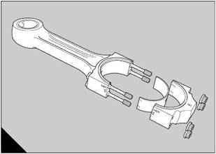
The connecting rods (A) are made from chromium
molybdenum steel forgings and are machined to
13
receive bearings at the small end, which are bushes
of the split type. The bushes are rolled and have steel
backs with bearing surfac es of lead bronze. They are
pressed into the eye of the small end with the split in
the upper half at 45 degrees to align the oil hole of the
bush with the oil hole of the connecting rod. The
position of the oil hole is 135 degrees from the split.
The small end of each connecting rod is wedge
shaped to conform with the pressure on the small end
and the piston. An oil hole is drilled axially through the
centre of the connecting rod to provide an intermittent
supply of oil under pressure from the crank pin to
lubricate the small end and the gudgeon pin.
Four special bolts and nuts, are used to retain each
bearing cap to its relevant connecting rod. There are
marks on the assembly of each connecting rod which
give the weight, the relationship of the cap to the rod,
and, if relevant, the number of the cylinder bore.
The big end bearings are similar to the main bearings,
but they do not have grooves in the bearing surfaces.
It is important that the larger chamfer in the bore of
each big end is to the outside of the two connecting
rods which are fitted on each crank pin.
The half bearings are held in their positions by the big
end bolts. The shoulders around the centres of the
bolts fit in the grooves whic h are machined in the
outer face at each end of a half bearing. The grooves
are off-centre to the bearing and, therefore, the half
bearing mus t be fitted correctly.
The weight of each connecting rod, together with the
small end bush, the bearing cap, the big end bolts and
the nuts, is measured during its manufacture, and it is
stamped with a letter (or for new engines, a letter and
a number) which indicates its group according to its
weight.
A
200
Perkins Engines Company Limited
61
This document has been printed from SPI². Not for Resale