 English
 Espaol
 Franais
 阿拉伯
阿拉伯 中文
中文 Deutsch
 Italiano
 Português
 日本
日本 韩国
韩国 български
 hrvatski
 esky
esky Dansk
Dansk Nederlands
 suomi
suomi Ελληνικ
 印度
印度 norsk
norsk Polski
 Roman
Roman русский
 Svenska
Perkins3012柴油发动机威尔逊P850E柴油发电机配件曲轴瓦供应商,Perkins3012柴油发动机威尔逊P850E柴油发电机配件曲轴瓦技术价格规格咨询服务,Perkins3012柴油发动机威尔逊P850E柴油发电机配件曲轴瓦零配件供应,Perkins3012柴油发动机威尔逊P850E柴油发电机配件曲轴瓦售后服务中心,Perkins3012柴油发动机威尔逊P850E柴油发电机配件曲轴瓦,Perkins3012柴油发动机威尔逊P850E柴油发电机配件曲轴瓦详细的技术参数,

产品中心
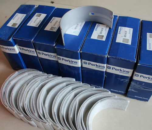
Perkins3012柴油发动机威尔逊P850E柴油发电机配件曲轴瓦
详细描述
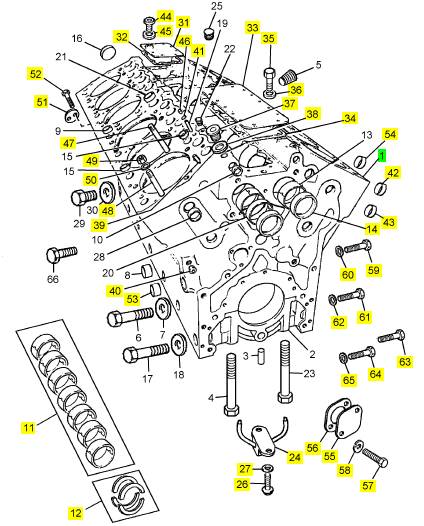
项目 零配件号码 最近的部分号码 描述
1 CV14877/1 Z 1 CV14877/1 Z 曲桥箱
11 KRP3106/010 1 KRP3106/010 曲轴瓦装备 -U/S
11 KRP3106/020 1 KRP3106/020 曲轴瓦装备 -U/S
11 KRP3106/030 1 KRP3106/030 曲轴瓦装备 -U/S
11 KRP3106/040 1 KRP3106/040 曲轴瓦装备 -U/S
11 KRP3106 1 KRP3106 曲轴瓦装备
12 KRP3203/013 1 KRP3203/013 插入垫圈装备 -O/S
12 KRP3203 1 KRP3203 止推片装备
14 CV275 2 CV275 栓塞
24 CV9116 6 CV19408 喷射
26 ST44441 12 2314 C045 固定螺钉
27 ST43160 12 2134 A008 垫圈
31 CV1418 1 CV1418 板
32 CV20207 1 CV20207 切片密封垫的板
33 CV1420 1 CV1420 板
34 CV20208 1 CV68115 密封垫
35 ST44437 22 2314 C043 固定螺钉
36 ST20606 22 ST20606 垫圈
37 ST20133 1 ST20133I 栓塞
38 ST49891 1 ST49891 垫圈
39 ST45779 8 ST45779 合钉
40 ST20704 5 ST20704 栓塞
41 OE7669 4 OE7669 密封O型圈
42 CV13080 4 CV13080 栓塞
43 ST43324 4 ST43324 栓塞
44 ST20134 1 ST20134 栓塞
45 ST49206 1 ST49206 垫圈
46 CV1470 4 CV1470 线桥
47 CV7789 48 CV7789 图钉
48 CV7790 32 CV7790 图钉
49 CV7788 80 CV7788 螺帽
50 OE46176 80 OE46176I 垫圈
51 CV2910 1 CV2910 栓塞
52 CV20002 2 CV20002 固定螺钉
53 ST43333 1 ST43333 栓塞
54 ST43330 1 ST43330 栓塞
55 OE1647 1 OE1647 盖
56 CV20236 1 CV20236I 密封垫
57 ST43556 2 ST43556 螺拴
58 2134 A010 2 2134 A010 垫圈
59 ST20103 1 ST46078I 栓塞
60 ST49853 1 ST49853 垫圈
61 ST20104 1 ST20104 栓塞
62 ST49891 1 ST49891 垫圈
63 ST20105 1 ST20105 栓塞
64 ST20107 1 ST20107 栓塞
65 ST49209 1 ST49209 垫圈
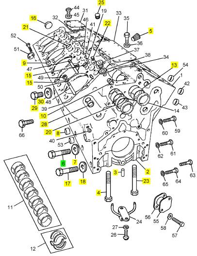
项目 零配件号码 最近的部分号码 描述
2 7 帽
3 CV270 1 CV270 合钉
4 CV278 8 CV24546 固定螺钉
5 ST20707 1 ST20707 栓塞
6 ST43706 8 ST43706 螺拴
7 ST43060 8 2131 A016 垫圈
8 ST43330 12 ST43330 栓塞
9 ST43326 10 ST43326 栓塞
10 ST33606 4 ST33606 栓塞
13 CV274 17 CV274 凸轮轴衬套
15 ST43322 20 ST43322 栓塞
16 ST43326 1 ST43326 栓塞
17 ST43657 6 ST43657 螺拴
18 CV9171 6 CV9171 垫圈
20 CV11572 1 CV11572 凸轮轴衬套
21 ST43328 2 ST43328 栓塞
22 ST20701 29 ST20701 栓塞
23 CV1271 12 固定螺钉
25 ST20702 2 ST20702 栓塞
28 ST43324 8 ST43324 栓塞
29 ST46076 1 ST46076I 栓塞
30 ST49851 1 ST49851 垫圈
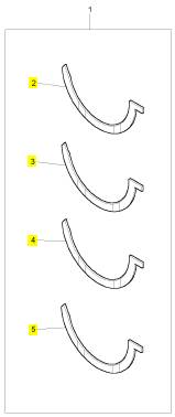
项目 零配件号码 最近的部分号码 描述
2 1 止推片
3 1 止推片
4 1 止推片
5 1 止推片
项目 零配件号码 最近的部分号码 描述
ST20139 2 ST20139 栓塞
ST49860 2 ST49860 垫圈
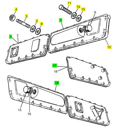
1 CV5519 1 室
3 CV2124 8 CV2124 图钉
4 ST44605 8 2318 A208 公制的螺帽
5 ST43160 8 2134 A008 垫圈
6 ST43056 8 2131 A008 垫圈
7 CV7210/1 1 CV7210/1 冷却器回廊装备
7 CV7210/1 1 CV7210/1 冷却器回廊装备
7 CV7210 1 CV7210/1 冷却器回廊
10 CV20232 4 CV72181 密封垫
11 ST43502 48 ST43502 螺拴
12 ST43160 48 2134 A008 垫圈
13 ST43056 48 2131 A008 垫圈
14 CV7211/1 1 CV7211/1 冷却器回廊装备
14 CV7211/1 1 CV7211/1 冷却器回廊装备
14 CV7211 1 CV7211/1 冷却器回廊
17 CV5595 1 CV5595 室
项目 零配件号码 最近的部分号码 描述
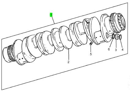
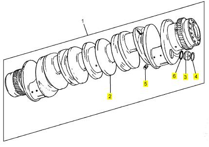
1 CV13835 1 CV24559 曲轴装备
项目 零配件号码 最近的部分号码 描述
2 1 曲轴
3 CV13458 6 CV13458 栓塞
4 CV1209 6 CV1209 扣环
5 CV13830 3 CV13830 栓塞
6 ST10609 6 ST10609 密封O型圈
项目 零配件号码 最近的部分号码 描述
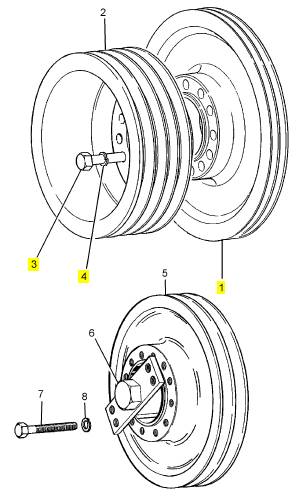
1 CV7926 1 曲轴皮带轮
3 CV12174 12 CV12174 螺拴
4 2134 A012 12 2134 A012 垫圈
All rods which have the same letter have weights
which vary by less than 0,10 kg (0.22 lb) and rods
which have the same letter and number have weights
which vary by less than 0,025 kg (0.055 lb). If a
connecting rod is to be renewed, it important that the
new connecting rod is of the same group as the
original connecting rod.
The groups for the weights are as follows:
Y1 4,150 kg to 4,175 kg (9.149 to 9.204 lb)
Y2 4,175 kg to 4,200 kg (9.204 to 9.259 lb)
Y3 4,200 kg to 4,225 kg (9.259 to 9.315 lb)
Y4 4,225 kg to 4,250 kg (9.315 to 9.370 lb)
Z1 4.250 kg to 4,275 kg (9.370 to 9.425 lb)
Z2 4.275 kg to 4,300 kg (9.425 to 9.480 lb)
Z3 4.300 kg to 4,325 kg (9.480 to 9.535 lb)
Z4 4.325 kg to 4,350 kg (9.535 to 9.590 lb)
A1 4,350 kg to 4.375 kg (9.590 to 9.645 lb)
A2 4,375 kg to 4.400 kg (9.645 to 9.700 lb)
A3 4,400 kg to 4.425 kg (9.700 to 9.755 lb)
A4 4,425 kg to 4.450 kg (9.755 to 9.811 lb)
B1 4,450 kg to 4,475 kg (9.811 to 9.866 lb)
B2 4,475 kg to 4,500 kg (9.866 to 9.921 lb)
B3 4,500 kg to 4,525 kg (9.921 to 9.976 lb)
A
139
B4 4,525 kg to 4,550 kg (9.976 to 10.031 lb)
C1 4,550 kg to 4,575 kg (10.031 to 10.086 lb)
C2 4,575 kg to 4,600 kg (10.086 to 10.141 lb)
C3 4,600 kg to 4,625 kg (10.141 to 10.196 lb)
C4 4,625 kg to 4,650 kg (10.196 to 10.252 lb)
D1 4,650 kg to 4,675 kg (10.252 to 10.307 lb)
D2 4,675 kg to 4,700 kg (10.307 to 10.362 lb)
D3 4,700 kg to 4,725 kg (10.362 to 10.417 lb)
D4 4,725 kg to 4,750 kg (10.417 to 10.472 lb)
E1 4,750 kg to 4,775 kg (10.472 to 10.527 lb)
E2 4,775 kg to 4,800 kg (10.527 to 10.582 lb)
E3 4,800 kg to 4,825 kg (10.582 to 10.637 lb)
E4 4,825 kg to 4,850 kg (10.637 to 10.692)
The grades of the connecting rods fitted within a bank
of cylinders must all be the same; for example, ’A’
bank - all grade B1. A different grade of connecting
rod may be fitted in the other bank of cylinders, but
they must also be all the same within the bank; for
example, ’B’ bank - all C3.
The pistons are made of an aluminium alloy which
contains a high percentage of silicon. The tops of the
pistons have special toroidal combustion chambers to
give an efficient mix of fuel and air. Each of the early
pistons (A) has three compression rings and one oil
control ring. The new pistons have two compression
rings and one oil control ring. The top compression
rings of both types of pistons are wedge shaped and
their grooves are machined in hard metal inserts to
reduce the wear of the grooves.
Each 4-ring piston is tin plated on all the surfaces after
it has been manufactured, except the bore for the
gudgeon pin.
A 3-ring piston is tin plated below the top ring, except
the bore for the gudgeon pin, and the toroidal
combustion chamber is hard anodised. The axial
location of the fully floating gudgeon pin is controlled
by the circlips in the bore.
62
Perkins Engines Company Limited
This document has been printed from SPI². Not for Resale
![]() Big end bearings
Big end bearings
13
To remove and to fit
Special tools:
Guide pin, 21825 843
13-1
To remove
1 Disconnect the batteries, stop the supply of the fuel
and drain the engine lubricating oil from the sump.
2 Remove the lubricating oil sump, operation 19-1 or,
for new engines, operation 19-5.
3 For early engines, remove the sump adaptor,
operation 19-3.
4 If necessary, release the bolts which retain the
lubricating oil pump and remove the lubricating oil
pump, operation 19-7.
5 Turn the crankshaft until the selected assembly of
the piston and connecting rod is at the bottom of its
stroke and remove the nuts of the big end bolts.
Remove the bearing cap and fit the guide pin, 21825
843, on to one of the big end bolts. Push carefully the
assembly up the cylinder bore just enough to allow
access to the upper half bearing.
Caution: There is a danger that the connecting rod
could fall against the cylinder liner and break it. The
use of the guide pin, 21825 843, ensures that this
damage cannot occur.
6 Remove the two half bearings from the connecting
rod and keep them together. Ensure that they can be
fitted in their original positions, if necessary.
To fit
1 Clean the connecting rod and the cap.
Caution: Renew the half bearings as a set of two if
there is doubt that they are acceptable for a complete
period of service. If it is not necessary to renew the
half bearings, ensure that they are fitted in their
original positions.
2 Clean the upper half bearing and lubricate the
bearing surface, the crank pin and the bolts and nuts
with clean engine lubricating oil. It is recommended
that new bolts and nuts are used. When the bolts are
fitted, press carefully each bolt into the connecting rod
until the bolt head is fully against the machined face
of the connec ting rod.
Perkins Engines Company Limited
63
This document has been printed from SPI². Not for Resale
 13
13
3 Fit the off-centre upper half bearing to the
connecting rod. Ensure that the edges of the half
bearing are aligned with the edges of the parent bore
of the connecting rod. When it is fitted correctly, the
half bearing does not protrude ov er the chamfer on
the edge of the bore.
4 Use the guide pin, 21825 843, to pull the assembly
of the connecting rod and the piston down the bore
until the big end bearing is fitted on the crank pin.
Remove the guide pin from the connecting rod.
5 Clean the off-centre lower half bearing and fit it to
the cap. Ensure that the edges of the half bearing are
aligned with the edges of the parent bore of the
A
114
connecting rod. When it is fitted correctly, the half
bearing does not protrude over the chamfer on the
edge of the bore. Lubricate the bearing surface and
the crank pin. Ensure that the letters/numbers, which
are stamped on each bearing cap to give its
relationship, match the letters/numbers which are
stamped on the connecting rod, and fit the bearing
cap onto the bolts of the big end. Ensure that the
connecting rod does not fall from the crank pin.
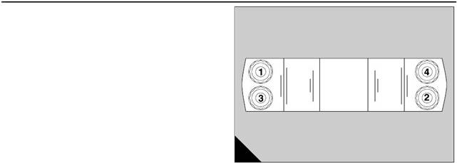
6 For engines fitted with connecting rod bolts which
have a ’D’ or square-shaped head, fit and tighten the
four nuts of the connecting rod, in the sequence
shown (B), to 20 Nm (15 lbf ft) and then to 45 Nm (33
lbf ft). The final operation is to tighten them to 70 Nm
(52 lbf ft). During the operation to tighten the bolts, if
the tension on the torque wrench reduces suddenly,
remove the bolt and fit a new bolt and nut.
For early engines, those with round headed
connecting rod bolts, proceed as follows: fit and
tighten the four nuts of the connecting rod, in the
sequence shown (B) to 20 Nm (14 lbf ft) and then to
40 Nm (28 lbf ft). The final operation is to tighten them
to 60 Nm (42 lbf ft). During the operation to tighten the
bolts, if the tension on the torque wrench reduc es
suddenly, remove the bolt and renew the bolt and its
nut.
Caution: Round headed connecting rod bolts are
NOT interchangeable with the later ty pes. Connecting
rods must be fitted with only the type of bolts which
were originally used.
7 Ensure that the crankshaft turns freely.
8 Fit the lubricating oil pump if relevant, operation 19-
7.
9 For early engines, fit the sump adaptor, operation
19-3.
10 Fit the lubricating oil sump, operation 19-1 or, for
new engines, operation 19-5.
11 Fill the sump to the correct level with engine
lubricating oil and connect the supply of the fuel.
12 Connect the batteries.
To inspect 13-2
1 Check the bearings and the crank pin for wear or
other damage.
64
Perkins Engines Company Limited
This document has been printed from SPI². Not for Resale
![]() Piston and connecting rod assembly
Piston and connecting rod assembly
13
To remove and to fit
Special tools:
Guide pin, 21825 843
Retainers, 21825 844
13-3
To remove
1 Disconnect the batteries, stop the supply of the fuel
and drain the engine lubricating oil from the sump
2 Drain the cooling system.
3 Remove the relevant cylinder head, operation 12-9.
4 Remove the lubricating oil sump, operation 19-1 or,
for new engines, operation 19-5.
5 For early engines, remove the sump adaptor,
operation 19-3.
6 If necessary, release the bolts which retain the
lubricating oil pump and remove the lubricating oil
pump, operation 19-7.
7 Hold the relevant cylinder liner with the retainers,
21825 844, as necessary.
8 Turn the crankshaft until the selected assembly of
the piston and connecting rod is at the bottom of its
stroke and remove the nuts of the big end bolts.
Remove the bearing cap and fit the guide pin, 21825
843, on to one of the big end bolts. Push carefully the
assembly out through the top of the cylinder.
Caution: There is a danger that the connecting rod
could fall against the cylinder liner and break it. The
use of the guide pin, 21825 843, ensures that this
damage cannot occur.
Perkins Engines Company Limited
65
This document has been printed from SPI². Not for Resale
 13
13
To fit
Special tools:
Height gauge, 21825 782
Guide pin, 21825 843
Retainer, 21825 844
Piston ring compressor, 21825 845
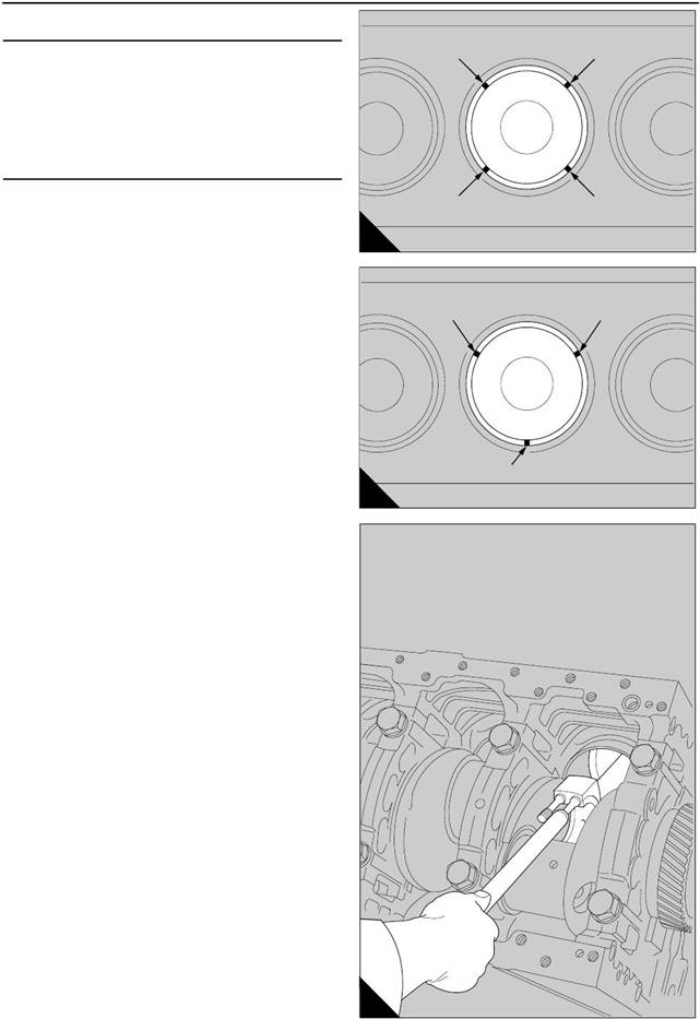
1 Turn the crankshaft until the relevant crank pin is at
BDC. Check that the upper half bearing of the big end
is in its position on the connecting rod. Set the gaps
of the piston rings in the positions shown (A) if the
pistons have four rings. If the pistons have three
rings, set the gaps as shown (B). Apply oil to the
crank pin, the upper half bearing and the piston, and
slide the piston ring compressor, 21825 845, over the
lower end of the piston with the tapered section
against the piston rings. Fit the guide pin, 21825 843,
onto one of the bolts of the big end bearing (C). It is
recommended that new bolts and nuts are used.
When the bolts are fitted, press carefully each bolt
into the connecting rod until the bolt head is fully
against the machined face of the connecting rod.
Caution: There is a danger that the connecting rod
could fall against the cylinder liner and break it. The
use of the guide pin, 21825 843, ensures that this
damage cannot occur.
Caution: If the old bolts and nuts have been used for
the connecting rod, they must first be inspected, for
signs of distortion of the threads, for stress, or for
indications of stretch, etc. Renew all bolts and nuts
that could be defective.
2 Fit carefully the assembly of the piston and the
connecting rod into its liner. Ensure that the cutout in
the lower wall of the piston is in the correct
relationship to the piston cooling jet assembly. Use
the guide pin to pull the assembly through the piston
ring compres sor and into the cylinder liner. Ensure
that the piston ring compressor is held, and does not
fall when it becomes free. Continue to pull the
assembly until the big end bearing is fitted on the
crank pin. If the piston and the connecting rod are
assembled correctly, the chamfer on the edge of the
bore in the big end is toward the crankshaft web.
Ensure that there is clearanc e between the piston and
the cooling jet.
Caution: During this operation, do not damage the
bearing surfaces of the crank pin and the half
bearings of the big end.
A
B
12
13
A
194
66
Perkins Engines Company Limited
This document has been printed from SPI². Not for Resale
 13
13
Caution: If a retainer, 21825 844, is removed to give
a clearance for the piston ring compressor, it must be
fitted again for each operation before the crankshaft is
turned.
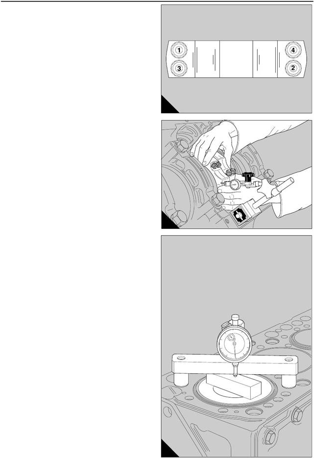
3 Fit and tighten the four nuts of the connecting rod,
in the sequence shown (A) to 20 Nm (15 lbf ft) and
then to 40 Nm (30 lbf ft). The final operation is to
tighten them to 60 Nm (44 lbf ft). It is recommended
that the new bolts and nuts are used. Lubricate lightly
the threads and the contact faces before they are
fitted to the connecting rods.
Caution: The nuts of the connecting rod should be
tightened gradually and evenly. During this operation
avoid rapid or sudden movements of the torque
wrench.
4 Ensure that the crankshaft turns freely .
5 Check the end-float of the connecting rods with a
dial test indicator, as shown (B). The clearance for
each set of two connecting rods, between the big
ends and their relevant crankshaft webs, must be
0,20 mm to 0,40 mm (0.008 to 0.016 in).
6 Repeat the procedure for each assembly of a piston
and a connec ting rod.
Check the clearance between the top face of the
piston and the top face of the cylinder bank as follows:
7 Put the setting plate of the height gauge, 21825
782, on a clean s urface which is machined and put
the base of the tool over the setting plate. Align the
button of the dial gauge to make contact with the
centre of the plate. Set the dial gauge to zero and
tighten the locking screw.
8 Turn the crankshaft until one of the pistons is
almost at the top of its cylinder and move the setting
plate to the top face of the piston. Put the base of the
tool on the top face of the cylinder block, as shown
(C).
9 Continue to turn slowly the c rankshaft, to allow the
piston to pass TDC. As the piston passes TDC, make
a note of the reading on the dial gauge; the maximum
deflection of the pointer gives a minimum reading to
indicate the clearance between the top face of the
piston and the top face of the cylinder bank. The
permis sible clearance is from 0,31 to 0,38 mm (0.012
to 0.015 in). For engines manufactured from July
1998, fitted with piston number CV66887, the
permis sible clearance is from 0,31 to 0,75 mm (0.012
to 0.029 in).
A
B
114
197
B
198
Perkins Engines Company Limited
67
This document has been printed from SPI². Not for Resale
![]() 13
13
10 Check the clearance of each piston in the
cylinders of ’A’ bank, then turn the crankcase until the
cylinders of ’B’ bank are vertical. Repeat the
procedure to check the clearance of each piston in the
cylinders of ’B’ bank.
Caution: If not enough clearance is shown on the
dial gauge, the top face of the piston must be
machined to remove the minimum amount of material
which is necessary to give the correct clearance. This
will not be neces sary for engines manufactured after
July 1998 fitted with the piston XCV66887.
11 Fit the cylinder head, operation 12-9.
12 Fit the lubricating oil pump if relevant, operation
19-7.
13 For early engines, fit the sump adaptor, operation
19-3.
14 Fit the lubricating oil sump, operation 19-1 or, for
new engines, operation 19-5.
15 Fill the sump to the correct level with engine
lubricating oil and connect the supply of the fuel.
16 Fill the cooling system.
17 Connect the batteries.
To dismantle and to assemble 13-4
To dismantle
1 Remove the circlips which retain the gudgeon pin.
2 Push the gudgeon pin out by hand to release the
connecting rod. If the gudgeon pin is tight, heat the
piston in a tank of warm water. Keep together each
assembly.
To assemble
Before the connecting rod is assembled, check for
dirt and debris in the passage for the lubricating oil
and clean the pas sage with compressed air.
1 The gudgeon pin should be a push fit at 20°C
(68°F). If it is tight in its bore in the piston, heat the
piston in a tank of warm water. Remove the piston
from the water and use a clean and suitable rag to dry
the bore for the gudgeon pin. Fit one of the circlips
into its groove in the bore.
2 Give an applic ation of clean engine lubric ating oil to
the small end bush, the gudgeon pin and the bore for
the gudgeon pin.
68
Perkins Engines Company Limited
This document has been printed from SPI². Not for Resale