 English
 Espaol
 Franais
 阿拉伯
阿拉伯 中文
中文 Deutsch
 Italiano
 Português
 日本
日本 韩国
韩国 български
 hrvatski
 esky
esky Dansk
Dansk Nederlands
 suomi
suomi Ελληνικ
 印度
印度 norsk
norsk Polski
 Roman
Roman русский
 Svenska
Perkins3012柴油发动机威尔逊P850E柴油发电机配件水泵供应商,Perkins3012柴油发动机威尔逊P850E柴油发电机配件水泵技术价格规格咨询服务,Perkins3012柴油发动机威尔逊P850E柴油发电机配件水泵零配件供应,Perkins3012柴油发动机威尔逊P850E柴油发电机配件水泵售后服务中心,Perkins3012柴油发动机威尔逊P850E柴油发电机配件水泵,Perkins3012柴油发动机威尔逊P850E柴油发电机配件水泵详细的技术参数,

产品中心
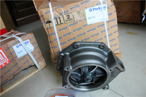
Perkins3012柴油发动机威尔逊P850E柴油发电机配件水泵
详细描述
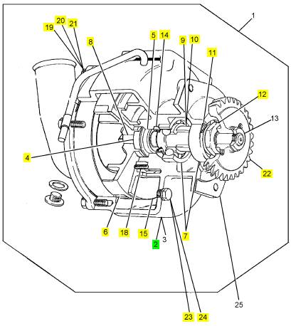
项目 零配件号码 最近的部分号码 描述
ST46076 1 ST46076I 栓塞
ST49851 1 ST49851 垫圈
1 CV14573/2 1 CV14573/2 水泵
25 CV1243 1 CV20206 密封垫
26 CVK533 1 CVK533 修理装备 - 水的泵
27 CVK534 1 CVK534 修理装备 - 水的泵
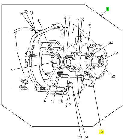
项目 零配件号码 最近的部分号码 描述
2 CV14576 1 CV14576 套
4 CV14309 1 CV20055 密封
5 CV14310 1 CV14310 计数器板
6 CV14574 1 CV14574 动叶轮
7 OE1376 2 OE1376 滚珠瓦
8 CV14575 1 CV14575 桥
9 CV1236 1 CV1236 间隔器
10 CV14053 1 CV14053 填隙用木片
11 ST48993 1 2721351 CIRCLIP
12 CV2235 1 CV2235 螺帽
13 CV2234 1 CV2234 螺帽
14 CV1234 1 CV1234 密封
15 CV1233 1 CV1233 圆盘
16 ST10965 1 ST10965 密封O型圈
17 CV5515 1 CV5515 肘管
18 ST46955 1 ST46955 螺旋
19 ST43502 5 ST43502 螺拴
20 ST43160 5 2134 A008 垫圈
21 ST43056 5 2131 A008 垫圈
22 CV1227 1 CV1227 水泵传动机构
23 ST46076 1 ST46076I 栓塞
24 ST49891 1 ST49891 垫圈
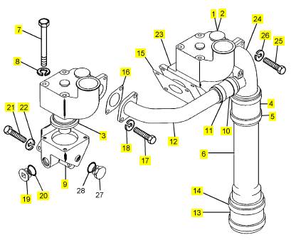
项目 零配件号码 最近的部分号码 描述
1 CV14258 2 CV14258 节温器壳
2 CV13582 2 CV13582 密封
3 CV20747 2 CV20747 节温器
4 ST91232 1 ST91232 水管
5 ST46411 2 ST46411 夹
6 CV14269 1 CV14269 水管
7 ST43515 8 ST43515 螺拴
8 2134 A008 8 2134 A008 垫圈
9 CV18442 1 CV18442 承接器
10 ST91204 1 ST91204 水管
11 ST46408 2 ST46408 夹
12 CV14263 1 CV14263 水管
13 ST91239 1 ST91239 水管
14 ST46412 2 ST46412 夹
15 CV19492 2 CV72491 密封垫
16 CV20383 2 CV20383 密封垫
17 2314 C045 3 2314 C045 固定螺钉
18 2134 A008 3 2134 A008 垫圈
19 ST20106 2 ST20106 栓塞
20 ST49856 2 ST49856 垫圈
21 ST43502 8 ST43502 螺拴
22 2134 A008 8 2134 A008 垫圈
23 CV14273 1 CV14273 承接器
24 CV14261 1 CV14261 连接
25 ST43511 1 ST43511 螺拴
26 2134 A008 1 2134 A008 垫圈
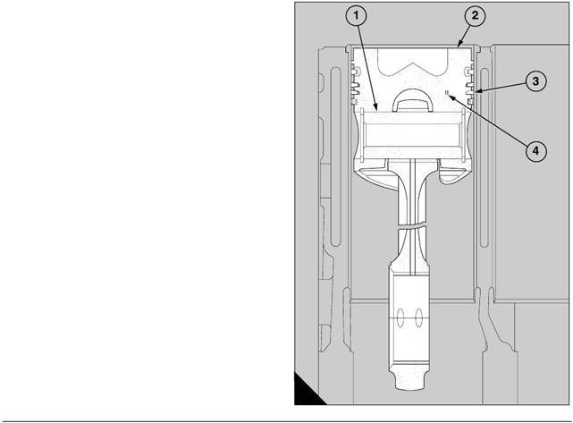
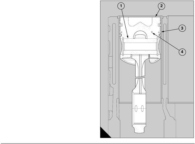
3 Insert the small end of the connecting rod into the
piston, and ensure that the cut-out in the lower wall of
the piston is on the opposite side to the larger c hamfer
in the bore of the big end.
4 Slide the gudgeon pin into the piston through the
small end bush and fit the second circlip into its
groove.
Caution: When the big-end bolts are to be fitted, the
flat surface, which is machined on the shoulder at the
centre of each bolt, must be away from the bore of the
big end. The half bearings will then engage correctly
in the bore of the connec ting rod. The shoulders of
new bolts do not have the flat surfaces and special
fitting instructions are not needed for them.
13
Perkins Engines Company Limited
69
This document has been printed from SPI². Not for Resale
![]() 13
13
Piston rings
To remove and to fit
Special tools:
Ring expander, 21825 793
13-5
To remove
1 Put the top face of the piston on the bench and use
the ring expander, 21825 793, with the location ring,
21825 874, to remove carefully each piston ring. Only
increase the ring gaps enough to ensure that the ends
of the rings do not damage the piston. Lift out the coil
spring from the groove for the oil control ring. Keep
the rings with their relevant piston.
To fit
1 Put the top face of the piston on the bench and
lubricate the grooves for the piston rings. Use the ring
expander, 21825 793, to fit carefully each piston ring
in the sequence given below. Only increase the ring
gaps enough to ensure that the ends of the rings do
not damage the piston.
2 Remove the coil spring from its oil control ring and
fit it around the bottom piston ring groove, with the
latch pin inside both ends of the spring, before the oil
control ring is fitted to the piston. Ensure that the
piston ring gap is at 180° to the latch pin.
The sequenc e of the assembly of the rings is:
Top - Barrel faced molybdenum
surface
Second - Chromium plated surface,
counterbore toward top of
piston
Third - 'Ferrox' treated surface,
counterbore toward top of
piston
Bottom - Composite chromium plated
oil control ring
70
Perkins Engines Company Limited
This document has been printed from SPI². Not for Resale
![]() Piston and rings
Piston and rings
Connecting rod
13
To inspect
13-6
To inspect
13-7
1 Soak the components in a solvent, such as ’Maxan’
or ’Ardrox 667’, to remove the carbon. Wash the
components in clean water and dry them with
compressed air.
2 Inspect the piston for wear, deep sc ratches, cracks
and further damage. Check that the wear in each
piston ring groove does not exceed the permissible
limits. If necessary, check the grooves by the use of
new piston rings.
3 Inspect the piston rings for wear, deep scratches
and signs of leakage. Discard the top ring if the
surface has large holes or cavities, or if there are
signs that the surface finish has started to break.
Compare the s urface with the surface of a new ring if
necessary.
4 Inspect the spring which is behind the oil control
ring. If the circumference of the spring is excessively
decreased, the spring and the oil control ring must be
renewed as a complete unit.
5 Check the gap of each piston ring in a new cylinder
liner, or in a portion of the original c ylinder liner which
is not worn. Discard a piston ring with a gap which
exceeds the limits given on page 73 or page 75.
Caution: When a new cylinder liner has been fitted,
the piston rings must also be renewed. When a new
piston ring is fitted into an original cylinder liner, the
bore of the cylinder liner must be honed or lapped to
break the glazed surface.
6 Check for cracks in the gudgeon pin and check also
its fit in the piston. The gudgeon pin should be a push
fit at 20°C (68°F). If the gudgeon pin is loose in its
bore, the assembly must be renewed.
Caution: An assembly of a piston and its gudgeon
pin must be renewed if the components do not
conform to the limits given in Fits and clearances at
the end of this section. If it is necessary to renew a
piston, it is also necessary to ensure that the
clearance is correct between the top of the new piston
and the top face of the cylinder bank by the use of the
height gauge, 21825 782, operation 13-3.
1 Clean the assembly of each connecting rod in
kerosene or a degreasing solution, and then check for
cracks in the rod, the big end cap and the big end
bolts.
Caution: It is recommended that the old bolts and
the old nuts of the assemblies of the connecting rods
should be discarded. Fit always new nuts to new
bolts and lubricate lightly the threads and the contact
faces before they are fitted to the connecting rods.
2 The bolts and the nuts of the assemblies of the
connecting rods must be inspected for signs of
distortion of the threads, for stress or for stretch, etc.
Renew all bolts which could be defective.
3 Check the small end bush for wear, for roughness
and for deep scratches. If a bush is damaged, it must
be renewed.
4 Inspect the half bearings of the big end for cracks,
for scratches and for contamination in the bearing
surfaces.
5 Check the alignment of the big end and of the small
end of the connecting rod. Do not try to correct a
connecting rod which is bent or twisted.
Perkins Engines Company Limited
71
This document has been printed from SPI². Not for Resale
 13
13
Fits and clearances - Pistons and connecting rods
Pistons - 4 rings
Gudgeon pin in piston (A1)
(Gudgeon pin to be push fit at 20°C)
Bore in piston (new) . . . . . . . . . . . . . . . . . . . . . . . . . . . . . . . . . . . . 54,999 to 55,004 mm (2.1653 to 2.1655 in)
Gudgeon pin diameter (new) . . . . . . . . . . . . . . . . . . . . . . . . . . . . . 54,995 to 55,000 mm (2.1652 to 2.1654 in)
Gudgeon pin in piston - clearance (new) . . . . . . . . . . . . . . . . . -0,001 to +0,009 mm (-0.00004 to +0.00036 in)
Top groove in piston
(wedge shaped for top ring CV 5907)
Diameter over 3,302 mm (0.1300 in) dia. Rollers . . . . . . . . . . . 136,073 to 135,855 mm (5.3572 to 5.3486 in)
Piston clearance at TDC (A2)
Top of piston below top face of crankcase. . . . . . . . . . . . . . . . . . . . . . . 0,310 to 0,380 mm (0.012 to 0.015 in)
(Machine top face of piston to obtain correc t clearance)
Piston rings
Clearances of piston rings in grooves (A3)
Top ring CV 5907 (wedge shaped - new) . . . . . . . . . . . . . . . . . . . . . . . . . . . . . . Refer to ring gap dimensions
Second ring OE41689 (new) . . . . . . . . . . . . . . . . . . . . . . . . . . . . . 0,0635 to 0,1016 mm (0.0025 to 0.0040 in)
Maximum permissible worn clearance . . . . . . . . . . . . . . . . . . . . . . . . . . . . . . . . . . . . . . . . 0,152 mm (0.006 in)
A
121
72
Perkins Engines Company Limited
This document has been printed from SPI². Not for Resale
Clearances of piston rings in grooves (continued)
Refer to the illustration (A) on page 72.
13
Third ring OE 42641 (new) . . . . . . . . . . . . . . . . . . . . . . . . . . . . . . 0,0635 to 0,1143 mm (0.0025 to 0.0045 in)
Maximum permissible worn clearance . . . . . . . . . . . . . . . . . . . . . . . . . . . . . . . . . . . . . . . 0,152 mm (0.006 in)
Oil control ring CV 5908 (new) . . . . . . . . . . . . . . . . . . . . . . . . . . . . . 0,049 to 0,086 mm (0.0019 to 0.0034 in)
Maximum permissible worn clearance . . . . . . . . . . . . . . . . . . . . . . . . . . . . . . . . . . . . . . . 0,152 mm (0.006 in)
Free length of coil spring (new) . . . . . . . . . . . . . . . . . . . . . . . . . . . 423,96 to 426,34 mm (16.691 to 16.785 in)
Piston ring gaps measured with ring in new liner (A4)
Top ring CV 5907 (new) . . . . . . . . . . . . . . . . . . . . . . . . . . . . . . . . . . . . 0,50 to 0,70 mm (0.0196 to 0.0275 in)
Maximum permissible worn gap . . . . . . . . . . . . . . . . . . . . . . . . . . . . . . . . . . . . . . . . . . . . 1,397 mm (0.055 in)
Second ring OE 41689 (new) . . . . . . . . . . . . . . . . . . . . . . . . . . . . . . . . 0,432 to 0,686 mm (0.017 to 0.027 in)
Maximum permissible worn gap . . . . . . . . . . . . . . . . . . . . . . . . . . . . . . . . . . . . . . . . . . . . 1,524 mm (0.060 in)
Third ring OE 42641 (new) . . . . . . . . . . . . . . . . . . . . . . . . . . . . . . . . . . 0,432 to 0,686 mm (0.017 to 0.027 in)
Maximum permissible worn gap . . . . . . . . . . . . . . . . . . . . . . . . . . . . . . . . . . . . . . . . . . . . 1,524 mm (0.060 in)
Oil control ring CV 5908 (new) . . . . . . . . . . . . . . . . . . . . . . . . . . . . . 0,430 to 0,810 mm (0.0169 to 0.0319 in)
Maximum permissible worn gap . . . . . . . . . . . . . . . . . . . . . . . . . . . . . . . . . . . . . . . . . . . . 1,016 mm (0.040 in)
Perkins Engines Company Limited
73
This document has been printed from SPI². Not for Resale
 13
13
Pistons - 3 rings
Gudgeon pin in piston (A1)
(Gudgeon pin to be push fit at 20°C)
Bore in piston (new) . . . . . . . . . . . . . . . . . . . . . . . . . . . . . . . . . . . . 54,999 to 55,009 mm (2.1653 to 2.1657 in)
Gudgeon pin diameter (new) . . . . . . . . . . . . . . . . . . . . . . . . . . . . . 54,995 to 55,000 mm (2.1652 to 2.1654 in)
Gudgeon pin in piston - clearance (new) . . . . . . . . . . . . . . . . . -0,001 to +0,014 mm (-0.00004 to +0.00055 in)
Top groove in piston
(wedge shaped for top ring CV 19329)
Diameter over 3,666 mm (0.1443 in) dia. rollers . . . . . . . . . . . . 135,155 to 135,405 mm (5.3211 to 5.3309 in)
Piston clearance at TDC (A2)
Top of piston below top face of crankcase. . . . . . . . . . . . . . . . . . . . . . . 0,310 to 0,380 mm (0.012 to 0.015 in)
(Machine top face of piston to obtain correc t clearance)
Piston rings
Clearances of piston rings in grooves (A3)
Top ring CV 19329 (wedge shaped) . . . . . . . . . . . . . . . . . . . . . . . . . . . . . . . . . . Refer to ring gap dimensions
Second ring CV 18638 (new). . . . . . . . . . . . . . . . . . . . . . . . . . . . . . . 0,067 to 0,090 mm (0.0026 to 0.0035 in)
Maximum permissible worn c learance . . . . . . . . . . . . . . . . . . . . . . . . . . . . . . . . . . . . . . . . 0,152 mm (0.006 in)
A
127
74
Perkins Engines Company Limited
This document has been printed from SPI². Not for Resale
Clearances of piston rings in grooves (continued)
Refer to the illustration (A) on page 74.
13
Oil control ring CV 18639 (new) . . . . . . . . . . . . . . . . . . . . . . . . . . . . 0,048 to 0,085 mm (0.0019 to 0.0034 in)
Maximum permissible worn clearance . . . . . . . . . . . . . . . . . . . . . . . . . . . . . . . . . . . . . . . 0,152 mm (0.006 in)
Free length of coil spring (new) . . . . . . . . . . . . . . . . . . . . . . . . . . . 423,96 to 426,34 mm (16.691 to 16.785 in)
Piston ring gaps measured with ring in new liner (A4)
Top ring CV 18637 (wedge shaped - new) . . . . . . . . . . . . . . . . . . . . . . 0,35 to 0,55 mm (0.0138 to 0.0217 in)
Maximum permissible worn gap . . . . . . . . . . . . . . . . . . . . . . . . . . . . . . . . . . . . . . . . . . . . 1,397 mm (0.055 in)
Second ring CV 18638 (new) . . . . . . . . . . . . . . . . . . . . . . . . . . . . . . . . . . 0,43 to 0,68 mm (0.017 to 0.027 in)
Maximum permissible worn gap . . . . . . . . . . . . . . . . . . . . . . . . . . . . . . . . . . . . . . . . . . . . 1,524 mm (0.060 in)
Oil control ring CV 18639 (new) . . . . . . . . . . . . . . . . . . . . . . . . . . . . . . . . 0,40 to 0,78 mm (0.016 to 0.031 in)
Maximum permissible worn gap . . . . . . . . . . . . . . . . . . . . . . . . . . . . . . . . . . . . . . . . . . . . 1,016 mm (0.040 in)
Perkins Engines Company Limited
75
This document has been printed from SPI². Not for Resale
 13
13
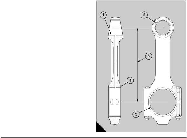
Connecting rods
Gudgeon pin in bush (A1)
Bore of bush. . . . . . . . . . . . . . . . . . . . . . . . . . . . . . . . . . . . . . . . . . 55,035 to 55,050 mm (2.1667 to 2.1673 in)
(Bush pressed into position and bored to size)
Diameter of gudgeon pin . . . . . . . . . . . . . . . . . . . . . . . . . . . . . . . . 54,995 to 55,000 mm (2.1652 to 2.1653 in)
Clearance (new). . . . . . . . . . . . . . . . . . . . . . . . . . . . . . . . . . . . . . . . . 0,035 to 0,055 mm (0.0014 to 0.0022 in)
Permissible worn clearance . . . . . . . . . . . . . . . . . . . . . . . . . . . . . . . . . . . . . . . . . . . . . . . 0,067 mm (0.0026 in)
Bush in small end (A2)
Bore in connecting rod . . . . . . . . . . . . . . . . . . . . . . . . . . . . . . . . . . . . 60,00 to 60,03 mm (2.3622 to 2.3633 in)
Diameter of bush . . . . . . . . . . . . . . . . . . . . . . . . . . . . . . . . . . . . . . . . 60,072 to 60,097 mm (2.365 to 2.366 in)
Interference fit . . . . . . . . . . . . . . . . . . . . . . . . . . . . . . . . . . . . . . . . . . 0,042 to 0,097 mm (0.0017 to 0.0038 in)
Alignment of connecting rod (A3)
Parallel alignment . . . . . . . . . . . . . . . . . . . . . . . . . . . . . . . . . . . . . . . . . . . . . . . . . . . . . . . 0,025 mm (0.001 in)
(Meas ured between big end and small end, for each 25,40 mm (1.000 in) of test mandrel)
Distance between centres . . . . . . . . . . . . . . . . . . . . . . . . . . . . . . . 273,05 to 272,95 mm (10.750 to 10.746 in)
End-float of big end (A4)
End-float. . . . . . . . . . . . . . . . . . . . . . . . . . . . . . . . . . . . . . . . . . . . . . . . . . . 0,20 to 0,40 mm (0.008 to 0.016 in)
Permissible worn end-float. . . . . . . . . . . . . . . . . . . . . . . . . . . . . . . . . . . . . . . . . . . . . . . . . 0,558 mm (0.022 in)
(End-float of each set of two big ends on common c rank pin)
Clearance on diameter of big end (A5)
Clearance. . . . . . . . . . . . . . . . . . . . . . . . . . . . . . . . . . . . . . . . . . . . . . . . 0,026 to 0,086 mm (0.001 to 0.003 in)
(Check that crank pin is within limits of ovality)
A
119
76
Perkins Engines Company Limited
This document has been printed from SPI². Not for Resale
 14
14
Crankshaft assembly
General description
14
Holes are drilled through the diameter of the main
journals. The holes are connected with holes in each
crank pin to supply lubricating oil to the big end
bearings of the connecting rods. The seventh main
journal at the rear of the crankshaft is not drilled.
For engines built up to build number 970208 the holes
are connected through each crankshaft web to the
reservoirs in the crank pins (A2). The oil flows to the
bearing surfaces of the crank pins from the reservoirs
The crankshaft is made from a forging of chromium
molybdenum steel. It is nitrided on all surfaces except
the tapped holes, the hole for the dowel and the end
faces at the front and the rear. The correct balance is
obtained when the crankshaft is machined, and there
is no requirement for further compensation when
assembled.
The 13 bearing s urfaces consist of seven main
journals and six crank pins. Each crank pin holds two
connecting rods.
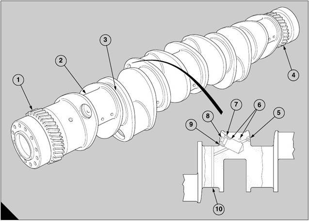
The crankshafts of engines manufactured up to build
number 970209 have an oil reservoir in each crank
pin. Access to clean each reservoir is provided by a
steel plug (A8) which is retained by a s pring clip (A9).
The crankshafts of engines from build number
970209 have an arrangement of passages which
removes the requirement for oil reservoirs.
through two holes (A6) which are drilled in each crank
pin.
The small holes in the crankshaft webs are sealed
with special blanking plugs (A5).
The crank pin arrangement is 1 and 6, 2 and 5, 3 and
4. Each set of two crank pins is aligned 120 degrees
from the other two sets. This gives a firing order of
A6, B1, A3, B4, A5, B2, A1, B6, A4, B3, A2 and B5.
A helical gear (A4) with 45 teeth is machined around
the rear end of the crankshaft and is the primary drive
for the timing gears. The face at the rear of the
crankshaft has 16 equally spaced tapped holes to
receive the cap screws which retain the flywheel. A
dowel of the spring type is fitted in a hole in the face
to ensure an accurate alignment of the timing mark on
the flywheel.
A
199
Perkins Engines Company Limited
77
This document has been printed from SPI². Not for Resale
![]() 14
14
A helical gear (A1) with 45 teeth is machined around
the front end of the crankshaft. The gear drives the
lubricating oil pump through an idler gear. The face at
the front end is drilled and tapped for 12 equally
spaced bolts, which retain the vis cous damper and
the multiple groove pulley for the fan drive belts.
The main bearings have steel backs with bearing
surfaces of lead bronze. The bearing surfaces have
|
To remove and to fit
To remove
14-1
a fine top lay er of lead indium.
The upper half of each bearing has a central groove
for oil around the inner surface. A hole is drilled in the
centre of the groove and is aligned with a hole in the
crankcase which supplies the oil.
The lower halves of the bearings do not have
grooves.
One end of each half bearing has a location tag which
is pressed away from one edge. The tags fit in
recesses which are machined in the crankcase and in
the bearing caps.
The thrust washers have steel backs with faces of
lead bronze. They are made in two halves which are
interchangeable. Each half has a location tag at one
end. The upper halves are fitted in recesses which
are machined in the crankcase on each side of the
central main journal; the lower halves are fitted in
recesses which are machined in the bearing cap.
Lubricating oil is supplied from the central main
bearing across the face of each washer, in which
grooves are machined to assist the flow of oil.
1 Release the large lock nut on the tensioner of the
fan belts and turn the adjustment screw to loosen the
fan belts. Remove the fan belts.
2 Remov e two horizontally opposite bolts from the
crankshaft pulley. Make locally two suitable guide
studs and fit them into the bolt holes.
3 Remove the remainder of the twelv e bolts from the
crankshaft pulley. Lift away the pulley for the fan
belts, followed by the damper and then the alternator
pulley from the guide studs.
Caution: The damper is a heavy component and
must not be allowed to fall during removal, because
distortion of the casing can prevent its correct
operation.
To fit
1 Fit the guide studs into the horizontally opposite
bolt holes in the end fac e at the front of the crankshaft.
Fit the alternator pulley on the guide studs, followed
by the damper and then the pulley for the fan belts.
2 Insert ten bolts, with their spring washers, through
the bolt holes and tighten securely the assembly to
the crankshaft. Remov e the guide studs and fit the
two remaining bolts and their spring washers.
3 Tighten each bolt to 80 Nm (59 lbf ft).
78
Perkins Engines Company Limited
This document has been printed from SPI². Not for Resale
 14
14
Front oil seal
To renew
Special tools:
Remover/replacer, 21825 905
14-2
To remove
1 Remove the crankshaft pulley, the damper and the
alternator pulley, operation 14-1.
2 Use the kit of the remover/replacer, 21825 905, to
remove and to replace the oil seal. Use the two short
setscrews in the kit to fit the top plate (A4) to the front
end of the crankshaft. Ensure that the counterbores
of the holes around the edge of the top plate are away
from the engine.
3 Use the centre punch in the kit, through the holes
around the edge, to either make three holes in the oil
seal, or to mark the centres in order to drill three holes
of a size which is s uitable to receive the three 40 mm
(1.5 in) long self-tapping sc rews in the kit.’
Caution: Three holes around the edge of the top
plate are marked ’A’ and three holes are marked ’B’.
Use the relevant group of holes which align centrally
A
129
with the metal of the seal.
4 Fit the three self-tapping screws through the holes
in the top plate into the holes in the seal. Do not
overtighten. Remove the setscrews which retain the
top plate and fit the three long screws of the kit.
Tighten evenly the screws against the end of the
crankshaft to pull out the seal. Remove the self-
tapping screws when the seal is withdrawn.
Perkins Engines Company Limited
79
This document has been printed from SPI². Not for Resale
 14
14
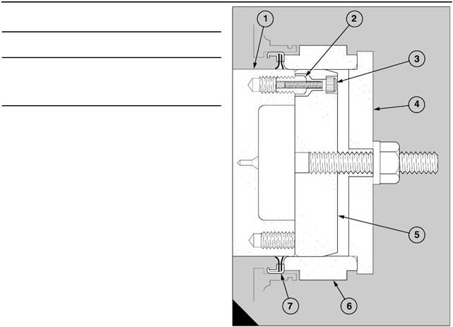
To fit
1 Ensure that the crankshaft, the fan adaptor and the
oil seal are clean. Use the kit of the remover/replacer,
21825 905, to fit the new oil seal at the front end of the
crankshaft. Fit the four special studs (A2) into four
equally spaced bolt holes in the end face of the
crankshaft (A1). Tighten lightly each special stud and
hold the guide (A5) agains t the end face of the
crankshaft.
2 Insert the four cap screws (A3), through the four
small holes in the guide, into the special studs. DO
NOT tighten the cap screws.
3 Slide the collar (A6) over the guide and the
crankshaft to ensure the concentricity of the guide on
the crankshaft. Tighten the four cap screws and
remov e the c ollar.
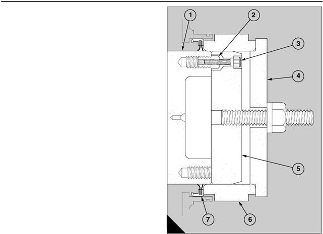
4 Before the new oil seal (A7) is fitted, check the
guide and the crank shaft for dirt or a rough surface
finish which could damage the lip of the oil seal.
5 Apply a small amount of clean engine lubricating oil
to the guide and the flange of the crankshaft, remove
and discard the yellow inner sleeve, and slide the seal
onto the parallel section of the guide. The lip of the
seal is toward the crankcase.
6 Slide the collar onto the guide until the face of the
collar presses against the outer face of the oil seal.
Caution: This tool is used for both CV8/3008 and
46
A
129
CV12/3012 engines and the collar is marked to show
the correct assembly for each engine. It is important
that the collar is fitted correctly. For CV12/3012
engines, the edge of the shorter of the two shoulders
which are machined on the collar must be against the
oil seal.
7 Fit the top plate (A4) onto the central stud and
engage its shoulder in the collar. Lightly lubricate the
thread of the stud and also the thrust washer. Fit the
nut and the thrust washer to retain the top plate. Use
the correct spanner to tighten the nut until the larger
diameter of the collar is in contact with the face of the
housing. Remove the complete tool.
8 Fit the crankshaft pulley, the damper and the
alternator pulley, operation 14-1.
80
Perkins Engines Company Limited
This document has been printed from SPI². Not for Resale
 14
14
Rear oil seal
To renew
Special tools:
Remover/replacer, 21825 810
14-3
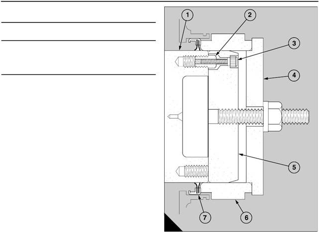
To remove
1 Remove the flywheel, operation 22-1.
2 Use the kit of the remover/replacer, 21825 810, to
remove and to replace the oil seal. Use the two short
setscrews in the kit to fit the top plate (A4) to the rear
end of the crankshaft. Ensure that the counterbores
of the holes around the edge of the top plate are away
from the engine.
3 Use the centre punch in the kit, through the holes
around the edge, to either make three holes in the oil
seal, or to mark the centres in order to drill three holes
of a size whic h is suitable to receive the three self-
tapping screws in the kit.
Caution: Three holes around the edge of the top
plate are marked ’A’ and three holes are marked ’B’.
Use the relevant group of holes which align centrally
with the metal of the seal.
A
129
4 Fit the three self-tapping screws through the holes
in the top plate into the holes in the seal. Do not
overtighten.
5 Remove the setscrews whic h retain the top plate
and fit the three long screws of the kit. Tighten evenly
the screws against the end of the crankshaft to pull
out the seal. Remove the self-tapping screws when
the seal is withdrawn.
To fit
1 Ensure that the crankshaft, the flywheel housing
and the oil seal are clean. Use the kit of the remover/
replacer, 21825 810, to fit the new oil seal at the rear
end of the crankshaft as follows:
Perkins Engines Company Limited
81
This document has been printed from SPI². Not for Resale