 English
 Espaol
 Franais
 阿拉伯
阿拉伯 中文
中文 Deutsch
 Italiano
 Português
 日本
日本 韩国
韩国 български
 hrvatski
 esky
esky Dansk
Dansk Nederlands
 suomi
suomi Ελληνικ
 印度
印度 norsk
norsk Polski
 Roman
Roman русский
 Svenska
Perkins3012柴油发动机威尔逊P850E柴油发电机配件连杆供应商,Perkins3012柴油发动机威尔逊P850E柴油发电机配件连杆技术价格规格咨询服务,Perkins3012柴油发动机威尔逊P850E柴油发电机配件连杆零配件供应,Perkins3012柴油发动机威尔逊P850E柴油发电机配件连杆售后服务中心,Perkins3012柴油发动机威尔逊P850E柴油发电机配件连杆,Perkins3012柴油发动机威尔逊P850E柴油发电机配件连杆详细的技术参数,

产品中心
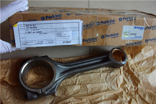
Perkins3012柴油发动机威尔逊P850E柴油发电机配件连杆
详细描述
项目 零配件号码 最近的部分号码 描述
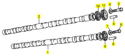
1 CV14543 1 CV14543 凸轮轴
2 CV14544 1 CV14544 凸轮轴
3 CV13282 6 CV13282 螺拴
4 2131 A010 6 2131 A010 垫圈
5 ST45780 1 ST45780 合钉
6 CV17071 6 CV17071 固定螺钉
7 2131 A008 6 2131 A008 垫圈
8 ST45778 1 ST45778 弹簧销
9 CV1214 1 CV1214 凸轮轴传动机构
10 CV1215 1 CV1215 凸轮轴传动机构
11 CV8563 1 CV8563 凸轮轴传动机构
项目 零配件号码 最近的部分号码 描述
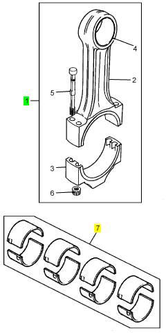
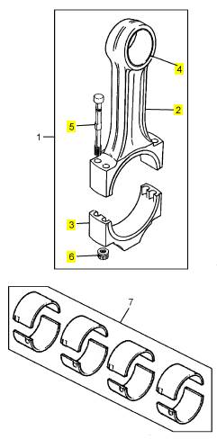
1 CV19260 12 连杆组合
7 KRP3010/010 1 KRP3010/010 连杆 BRG 装备 -U/S
7 KRP3010/020 1 KRP3010/020 连杆 BRG 装备 -U/S
7 KRP3010/030 1 KRP3010/030 连杆 BRG 装备 -U/S
7 KRP3010/040 1 KRP3010/040 连杆 BRG 装备 -U/S
7 KRP3010 3 KRP3010 连杆瓦装备
项目 零配件号码 最近的部分号码 描述
2 1 杆
3 1 帽
4 CV19259 1 CV19259 连杆小的一端衬套
5 CV999 4 CV999 连杆螺拴
6 CV206 4 CV206 连杆螺帽
2 Fit the dowel, which provides the location for the
flywheel, into its hole in the end face of the crankshaft
and align the guide (A5) for the seal, to ensure that
the dowel enters a hole in the guide. The hole is a
clearance fit on the dowel. Make a temporary mark
on the flange of the crankshaft to show the alignment
of the three bolt holes in the guide.
3 Lift away the guide and fit the three special studs
(A2) of the kit into the three relevant bolt holes in the
end face of the crankshaft (A1). Tighten lightly each
special stud, engage correctly the dowel in the hole
and hold the guide against the end face of the
crankshaft.
4 Insert the three cap screws (A3) of the kit through
the guide into the special studs and tighten lightly the
cap screws.
5 Before the oil seal (A7) is fitted, c heck again the
guide and the crank shaft for dirt or for a rough surface
finish which could damage the lip of the oil seal.
6 Apply a small amount of clean engine lubricating oil
to the guide and the flange of the crankshaft, remove
and discard the yellow inner sleeve, and fit the seal
onto the guide. The lip of the seal is toward the
crankcase.
7 Slide the collar (A6) onto the guide until the face of
the collar presses against the outer face of the oil
seal.
A
129
Caution:
This tool is used for both CV8/3008 and
CV12/3012 engines and the collar is marked to show
the correct assembly for each engine. It is important
that the collar is fitted correctly. For CV12/3012
engines, the edge of the shorter of the two shoulders
which are machined on the collar must be against the
oil seal.
8 Fit the top plate (A4) onto the central stud and
engage its shoulder in the collar. Lightly lubricate the
thread of the stud and also the thrust washer. Fit the
nut and the thrust washer to retain the top plate. Use
the correct spanner to tighten the nut until the larger
diameter of the collar is in contact with the face of the
housing. Remove the complete tool.
9 Fit the flywheel, operation 22-1.
82
Perkins Engines Company Limited
This document has been printed from SPI². Not for Resale
![]() Crankshaft
Crankshaft
14
To remove and to fit
Special tools:
Lift adaptor, crankshaft VP 666
Slide hammer, 21825 849
Remover tool, 21825 858
Guide pin, 21825 843
14-4
To remove
1 Fit the engine in the build stand, operation 16-1.
2 Remove the fan adaptor and the front mountings,
operation 21-10.
3 Remove the flywheel and the flywheel housing,
operation 22-4.
4 Remove the timing case and the timing gears,
operation 15-5.
5 Remove the lubricating oil sump, operation 19-1 or,
for new engines, operation 19-5.
6 For early engines, remove the sump adaptor,
operation 19-3.
7 Remove the lubricating oil pump, operation 19-7.
8 Turn the crankshaft until one of the pistons of ’A’
bank is at the bottom of its stroke and remove the four
nuts of the big end bearing. Withdraw the bearing cap
with the bearing. Fit the guide pin, 21825 843, on to
one of the bolts of the big end.
9 Push the assembly of the piston and the connecting
rod into its bore to the end of its stroke. Push carefully
to prevent damage to the top of the piston and the
valves.
10 Similarly, repeat the operation for the remainder of
the assemblies. Move the guide pin as necessary.
11 Turn the crankcase for acc ess to the big end
bearings of ’B’ bank. Repeat the operation for the
assemblies of pistons and connecting rods, as for ’A’
bank.Loosen all the bolts that retain the main bearing
caps. Release and remove the side bolts.
Perkins Engines Company Limited
83
This document has been printed from SPI². Not for Resale
 14
14
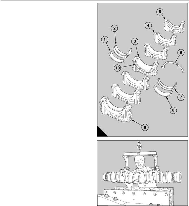
12 Remove the bolts from each main bearing cap and
remov e the caps. If necessary use the slide hammer,
21825 849, with the remover tool, 21825 858, to
withdraw each main bearing cap (A3,4,5,9) and its
lower half bearing (A1,8). When the central main
bearing cap (A3) is removed, remove also the lower
halves of the thrust washers (A10).
13 Slide the upper halves of the thrust washers (A6)
from their recesses around the central main journal.
Use the lift adaptor VP 666 to lift the crankshaft from
the crankcase and put it on wooden vee blocks.
Remove the upper halves of the main bearings (A2,7)
from the crankcase and also the upper halv es of the
thrust washers.
To fit
1 Check for dirt and debris in the passages for the
engine lubricating oil of the crankcase, and also of the
front and the rear main bearing caps (A5,9). Clean
thoroughly the bearing housings and the bearing
caps, and also the main journals and the crank pins of
the crankshaft.
2 Check also for dirt and debris in the passages of the
connecting rods and clean thoroughly the bearing
surfaces of the big ends.
3 Ensure that the half bearings and the thrust
washers for the main journals of the crankshaft are
absolutely clean, and fit the upper half bearings into
their housings in the crankcase. Give a full
application of clean engine lubricating oil to all of the
bearing surfaces.
4 Also, apply clean engine lubricating oil to lubricate
fully the main journals of the crankshaft. Use the lifting
beam VP 666 to lower the crankshaft into the
crankcase (B). Ensure that the 16 tapped holes in the
end face of the c rankshaft are furthest from the build
stand, and are at the end of the crankcase to which
the timing case is fitted.
5 Apply engine lubricating oil to the upper halves of
the thrust washers and insert them into their recesses
on each side of the central main bearing. Ensure that
the face of lead bronze on each washer is toward the
A
B
206
201
crankshaft web.
84
Perkins Engines Company Limited
This document has been printed from SPI². Not for Resale
 14
14
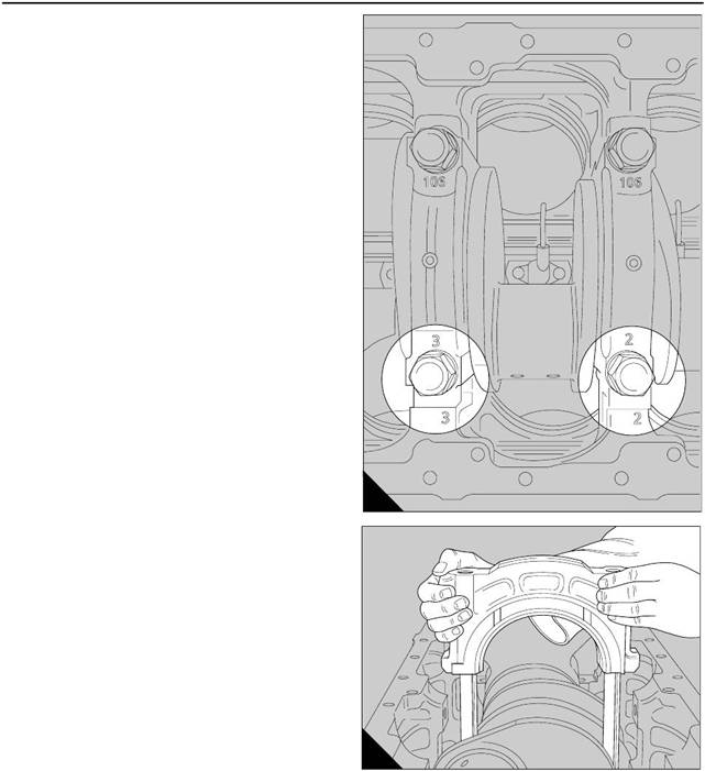
6 Fit the lower halves of the main bearings into the
bearing caps and give a full application of clean
engine lubricating oil to all of the bearing surfaces. Fit
all the ass emblies of the bearing caps except the
bearing cap for the central main bearing. Ensure that
the numbers which are stamped on each bearing cap,
to give its relationship, match the numbers which are
stamped on the crankcase, as shown (A).
7 Apply a minimum amount of grease to the recesses
at the sides of the bearing cap for the central main
bearing and insert the lower halves of the thrust
washers into the recesses. Ensure that the face of
lead bronze on each washer is away from the bearing
cap.
8 Fit carefully the assembly of the bearing cap for the
central main bearing. Ensure that the halves of the
thrust washers remain in their positions during the
operation.
9 Apply engine lubricating oil to the threads, and
under the heads, of the main bolts which retain the
main bearing caps. Fit carefully each bolt into its
location. Do NOT allow the bolts to fall into the holes
because the threads could be damaged. Insert fully
each main bolt by hand only.
Caution: On new engines, the bolts fitted to the front,
centre and rear bearing caps, are different and are
fitted with hardened washers. Ensure that the special
washers are fitted to the bolts before the bolts are
fitted to the engine. Do NOT fit any other type of
washer.
Caution: If a new front, centre or rear bearing cap is
fitted, do NOT fit the old type of bolts. The new bolts
and special washers MUST be used.
10 Apply engine lubricating oil to the threads, and
under the heads, of the side bolts which hold rigidly
the main bearing caps. Fit the plain washers on the
M16 bolts and the ’Dowty’ sealing washers on the
M14 bolts. Insert fully each bolt, by hand, through the
side walls of the crankcase.
11 Check that the faces which are machined on the
front and the rear of each main bearing cap are
A
B
203
202
aligned with the faces in the crankcase. Tighten
lightly all of the main bolts and then all of the side
bolts.
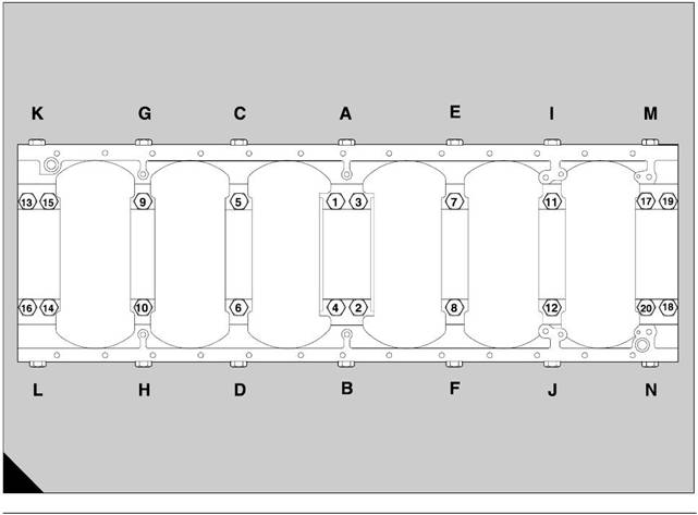
12 Tighten, in the sequence shown in page 86/B, all
the main bolts of the bearing caps by increments of 50
Nm (37 lbf ft) until the maximum torque of 177 Nm
(130 lbf ft) is applied. At the end of this phase of the
operation, the main bolts of the main bearing caps at
the front, at the c entre and at the rear are tightened
fully.
Caution: Check frequently that the crankshaft can
rotate freely while the bolts are tightened.
Perkins Engines Company Limited
85
This document has been printed from SPI². Not for Resale
 14
14
13 Continue to tighten the bolts - numbers 5 to 12 (B)
- for the remainder of the main bearing caps, until the
maximum torque of 488 Nm (360 lbf ft) is applied.
14 Tighten all the side bolts, in alphabetical
sequence, until a maximum torque of 114 Nm (85 lbf
ft) is applied. At the end of this phase of the operation,
the side bolts of the front, central and rear main
bearings are tightened fully.
15 Continue to tighten the remainder of the side bolts
- letters C to J (B) - in alphabetical sequence, until a
maximum torque of 177 Nm (130 lbf ft) is applied.
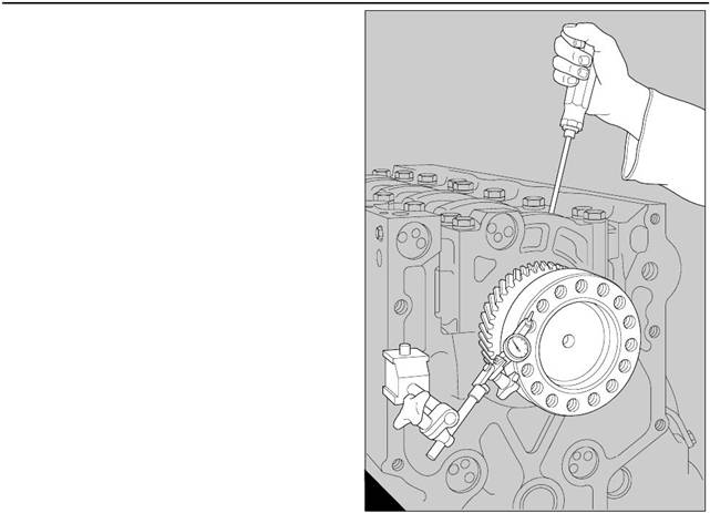
16 Put a dial test indicator with a magnetic base on
the end face of the crankcase. Set the button of the
dial test indicator on the end of the crankshaft (A).
Use a lever to move the crankshaft backward and
forward against the thrust washers and check the
readings on the dial test indicator. Permissible end-
float is 0,10 to 0,30 mm (0.004 to 0.012 in).
Turn the crankcase in the build stand so that the ’A’
bank cylinders are horizontal. Fit each of the
connecting rods, of the ’A’ bank cylinders, to their
respective crank pins, operation 13-3.
A
205
A
192
86
Perkins Engines Company Limited
This document has been printed from SPI². Not for Resale
17 When all of the ’A’ bank connecting rods have
been fitted, turn the build stand until the ’B’ bank
cy linders are horizontal and use the same procedure
to fit the connecting rods of the ’B’ bank.
18 Set a dial test indicator as shown (page 67/B) and
check the end float of each big end. The permissible
end float is 0,2 to 0,4 mm (0.008 to 0.016 in).
19 Ensure that the crankshaft turns freely.
20 Fit the lubricating oil pump, operation 19-7.
21 For early engines, fit the sump adaptor, operation
19-3.
22 Fit the lubricating oil sump, operation 19-1 or, for
new engines, operation 19-5.
23 Fit the timing case and the timing gears, operation
15-5.
24 Fit the flywheel and the flywheel housing,
operation 22-4.
25 Fit the fan adaptor, operation 21-10.
26 Remove the engine from the build stand,
operation 16-1.
14
Perkins Engines Company Limited
87
This document has been printed from SPI². Not for Resale
 14
14
To dismantle and to assemble
Special tools:
Lift adaptor, crankshaft VP 666
Remover/replacer, 27610005
14-5
To dismantle
1 Press down each plug (A1) of the reservoirs and
release the circlips. Fit the remover/replacer,
27610005 (A2), on the s pigot of the plug and withdraw
the plug. Early engines are fitted with a different type
of plug which has a threaded hole, for these engines
A
01
use remove/replacer, 21825 859, together with the
slide hammer, 21825 849. Clean all the components
with a degreasing solution.
To assemble
1 Fit new ’O’ ring seals to the blanking plugs of the
reservoirs. In sequence, apply a small amount of
’Stantyte’ lubricant or ’Morris’s liner lubricant’ around
the complete circumference of each housing in the
crankshaft. Press fully each plug into its housing and
fit the circ lip into its recess in the housing. Use the
relevant remover/replacer to pull backward the plug
4 Check for damage on the front and rear faces at the
ends of the crankshaft. Als o check for small marks on
the circumferences which are the location faces for
the flywheel and the pulley .
5 If the crankshaft is usable, small marks can be
removed from the journals, the crank pins, the thrust
faces and the locations on the ends by the use of a
very fine grade of oil stone.
Main bearings and thrust washers
against the circlip.
To clean and inspect
14-6
To inspect
14-7
To clean
1 Wash thoroughly the oil holes and reservoirs of the
crankshaft with kerosene and dry with compressed
air. Ensure that all surfaces of the crankshaft are
cleaned thoroughly.
To inspect
1 Hold the shaft in suitable wooden blocks under
main journals nos. 1 and 7. Check for crac ks in the
crankshaft, by the electro-magnetic method if
possible.
2 Check for damage and small marks on the main
journals, crank pins and thrust faces; check for ovality
the journals and crank pins. Refer to Perkins Engines
Company Limited, Shrewsbury, for the instructions
S.R.S. 121 Issue 2 for the repair of worn or damaged
journals and crank pins .
3 Hold the crankshaft in ’V’ blocks under the main
journals nos. 1 and 7 and check the amount of
deflection at the central main journal. The permissible
amount of the deflection, which is given on page 89,
must be gradual along the length of the crankshaft.
1 Remove the c rankshaft, operation 14-4.
2 Check for wear, cracks and contamination in the
surfaces of the bearings. Renew bearings as a set if
it is possible that a bearing will not complete a further
full period of service.
3 Check the thickness of the thrust washers.
Nominal dimensions for new thrust washers are:
2,93 to 3,0 mm (0.116 to 0.118 inch)
New thrust washers must be fitted if there is wear on
the thrust fac es and also if the crankshaft has
excessive end-float.
88
Perkins Engines Company Limited
This document has been printed from SPI². Not for Resale