 English
 Espaol
 Franais
 阿拉伯
阿拉伯 中文
中文 Deutsch
 Italiano
 Português
 日本
日本 韩国
韩国 български
 hrvatski
 esky
esky Dansk
Dansk Nederlands
 suomi
suomi Ελληνικ
 印度
印度 norsk
norsk Polski
 Roman
Roman русский
 Svenska
Perkins3012柴油发动机威尔逊P850E柴油发电机配件传感器供应商,Perkins3012柴油发动机威尔逊P850E柴油发电机配件传感器技术价格规格咨询服务,Perkins3012柴油发动机威尔逊P850E柴油发电机配件传感器零配件供应,Perkins3012柴油发动机威尔逊P850E柴油发电机配件传感器售后服务中心,Perkins3012柴油发动机威尔逊P850E柴油发电机配件传感器,Perkins3012柴油发动机威尔逊P850E柴油发电机配件传感器详细的技术参数,

产品中心
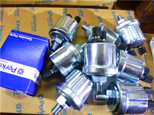
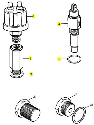
Perkins3012柴油发动机威尔逊P850E柴油发电机配件传感器
详细描述
项目 零配件号码 最近的部分号码 描述
1 CV18339/2 1 CH12894 油压传感器
2 CV18444 1 CV18444 承接器
3 ST49852 1 ST49852 垫圈
4 CV18338/5 1 CH12893 温度感应传感器
5 0920113 1 0920113 垫圈
 Fits and clearances
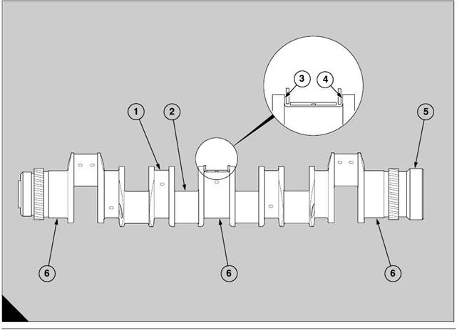
Crankshaft journals
Diameter (A1)145,975 to 146,000 mm (5.7470 to
5.7480 in)
Permissible worn dimensions145,910 mm (5.7445 in)
Ovality - permissible worn dimensions0,076 mm
(0.0030 in)
Journals in main bearings – clearance0,076 to 0,145
mm (0.0030 to 0.0057 in)
Crank pins
Diameter (A2)97,978 to 98,000 mm (3.8574 to 3.8583
in)
Diameter - permissible worn dimensions97,914 mm
(3.8548 in)
Ovality - permissible worn dimensions0,076 mm
(0.0030 in)
Deflection of crankshaft
Deflection of crankshaft (A6) when it is held in
'V' blocks under nos. 1 and 7 main journals0,1000 mm
(0.0039 in)
(Deflection must be gradual from outer main journals
to central main journal)
End float of crankshaft
Width between crankshaft webs of central journal
(A3)81,43 to 81,48 mm (3.2059 to 3.2079 in)
14
Width of central bearing (A4) across thrust washers
81,15 to 81,30 mm (3.1949 to 3.2008 in)
Clearanc e (new)0,13 to 0,33 mm (0.005 to 0.013 in)
Permissible worn clearance0,483 mm (0.019 in)
Flywheel on crankshaft
Bore of flywheel160,000 to 160,025 mm (6.2992 to
6.3002 in)
Diameter of crankshaft (A5)159,961 to 159,986 mm
(6.2976 to 6.2986 in)
Clearance (new)0,014 to 0,064 (0.0006 to 0.0026)
A
131
Perkins Engines Company Limited
89
This document has been printed from SPI². Not for Resale
14
90
Perkins Engines Company Limited
This document has been printed from SPI². Not for Resale
 15
15
Timing gears and timing case
General description
15
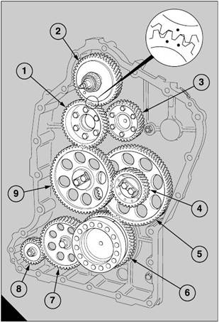
The timing gears (A) of the engine are protected by a
housing at the rear of the engine which has two
components, the timing case and the flywheel
housing.
The timing case is made from heavy-duty cast iron
and is bolted to the rear end of the crank case. It has
mountings for the connection block for the spill fuel,
the starter motor and the coolant pump. It holds the
inner bearing, and the housing for the oil seal, of the
auxiliary drive shaft.
For early engines, the oil seal of the auxiliary drive
shaft is s eparate and is pressed into its housing. The
current engine has a housing with an integral oil seal.
The housing also has an ’O’ ring in a groove around
its spigot to seal the bore in the timing case.
The fly wheel housing is also made from heavy-duty
cast iron and is bolted to the timing case. It holds the
outer bearing for the end of the aux iliary drive shaft
and has a mounting for the fuel lift pump. The correct
location of the assembly is ensured by a large dowel
and the axles of the idler gears in the timing case.
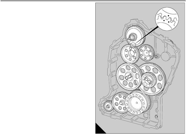
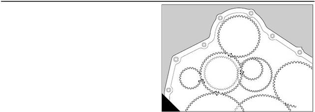
The arrangement of the timing gears consists of the
drive gear on the crankshaft (A6), the idler gear (A7)
for the drive to the gear of the coolant pump (A8), the
double idler gear (A4,5), the main idler gear (A9), the
drive gear for the fuel injection pump/camshafts (A1),
the two camshaft gears (A3) and the aux iliary drive
gear (A2). The drive gear for the fuel injection pump/
camshafts is bolted to the outer face of the camshaft
gear of ’B’ bank.
The axles of the idler gears are bolted to the rear end
of the crankcase and the end float of each gear is
limited by the thrust washers.
There are timing marks on the drive gear of the
crankshaft, the double idler gear, the main idler gear,
the drive gear for the fuel injection pump/camshafts,
the two camshaft gears and the auxiliary drive gear.
The use of the timing marks ensures that the mesh of
each gear is correc t, before the timing of the fuel
injection pump is checked and before the tappet
clearances are set. The teeth of the timing gears are
engaged correctly when the mark on the side of the
tooth of a gear is between the marks on the s ides of
two teeth of another gear (A).
A
132
Perkins Engines Company Limited
91
This document has been printed from SPI². Not for Resale
 15
15
Timing gears and auxiliary drive shaft
To remove and to fit
Special tools:
Puller, 21825 837
Bolts, 21825 839
Check plate, auxiliary drive gear, VT15279
15-1
To remove
A
191
To obtain access to the timing gears, the engine must
be disengaged from its driv en unit and its radiator,
and fitted in a build stand if it is av ailable, operation
16-1.
This operation includes the removal of the fan, the air
cleaners and the support brackets, the air ducts, the
coolant pipes and, if the engine is to be fitted in a build
stand, the front covers of the coolant galleries.
If a build stand is not av ailable, put the engine on
wooden supports on a strong hard floor and put a
secure support under the rear of the sump adaptor in
order to hold the flywheel housing above the floor.
1 Remove the starter motor, if the engine has not
been fitted in a build stand.
2 Open the cover on the flywheel housing and
remove the timing pointer.
3 Remove the flywheel, operation 22-1.
4 Disconnect the fuel pipes from the fuel lift pump and
the connection block for the spill fuel.
5 Remove the guard of the aux iliary drive.
6 Disconnect the delivery pipe for the lubricating oil
between the crankcase and the housing of the fuel lift
pump.
7 Remove the assembly of the mounting for the fuel
lift pump and release the nut which retains the cam on
the auxiliary drive shaft. Withdraw the spring washer
and the cam, and ensure that the ’Woodruff’ key is not
lost.
8 Disconnect and remove the fuel injection pump,
operation 20-11.
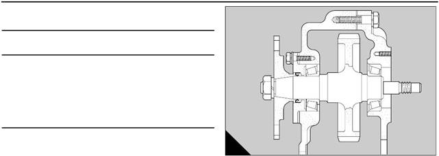
9 From the inner end of the auxiliary drive shaft (A),
release the nut that retains the flange of the coupling.
Remove the plain washer. Use the puller, 21825 837,
with the two bolts, 21825 839, to withdraw the flange.
Remove the Woodruff key. Before the engine is
dismantled further, check the backlash of the auxiliary
drive gear, if relevant to the job, as follows.
Perkins Engines Company Limited
92
This document has been printed from SPI². Not for Resale
 15
15
10 Put the special tool, VT15279, on the drive shaft
and retain it with the nut from the coupling flange. Put
a dial test indicator with a magnetic base in the ’V’ of
the crankcase. Set the button of the dial test indicator
on one of the faces of the special tool which is used
as a datum. Turn the s pecial tool to the limit of its
movement in both directions and check the reading
on the dial test indicator. The permissible backlash is
0,10 to 0,33 mm (0.004 to 0.013 in). Remove the
special tool.
11 Release the four bolts for early engines (six bolts
for new engines) which retain the housing for the oil
seal. Remove the housing and keep the pack of
laminated shims.
A
191
12 Remove the flywheel housing, operation 22-4.
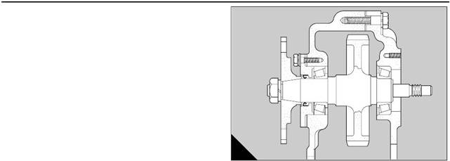
13 Withdraw the assembly of the auxiliary drive shaft
from the timing case, and remove and discard the oil
seal of the drive shaft. Current engines have
improved oil seals which are integral with their
housings and for these engines the housing must be
discarded.
During the operation to remove the timing gears,
check the backlash of each gear. Use generally the
method whic h is given for the assembly of the gears.
Make a record of the results.
To check the backlash of the camshaft gears, the
rocker boxes or pedestal rocker assemblies must be
removed, operation 12-5, or operation 12-2, to
release the pressure of the valve springs.
14 Turn backward one or two turns the nut which
retains the gear of the coolant pump. Remove the
four nuts and the spring washers from the s tuds which
retain the coolant pump and lift away the coolant
pump from the timing case.
15 Remove the nut which retains the gear and use
the puller, 21825 837, with the two bolts, 21825 839,
to withdraw the gear from the shaft of the coolant
pump.
16 Release and remove the bolt and the spring
washer from the axle of the idler gear for the coolant
pump. Lift away the assembly of the gear and the
axle.
17 Fit two 16 mm bolts, whic h are similar to the bolts
which retain the fly wheel, in the face at the rear end of
the crankshaft. These bolts should be used only to
turn the crankshaft with a suitable lever.
93
Perkins Engines Company Limited
This document has been printed from SPI². Not for Resale
 15
15
18 Turn the crankshaft until each location dowel of
the camshaft gears is toward the centre of the engine.
Remove the bolts which retain the camshaft gears
and us e levers to remove c arefully the drive gear of
the fuel injection pump/camshafts and the two
camshaft gears from the ends of the camshafts.
19 Bend backward the tabs of the lock plate of the
bolts which retain the assembly of the ax le for the
main idler gear. Release the bolts and remove the
assembly of the axle and the gear wheel.
20 Similarly, remove the double idler gear with the
assembly of its axle.
To fit
Check that the flanges at the drive ends of the
camshafts are clean and are not damaged. Turn the
crankshaft until the A6 piston is at TDC and fit the
assembly of the double idler gear as follows:
1 Slide the inner thrust washer, the assembly of the
gear, and the outer thrust washer onto the assembly
of the distance piece and the axle. Hold the
components in their positions on the distance piece.
Fit the assembly of the axle and the distance piece
through the timing case and into its recess in the end
face of the crankcase.
Ensure that the inner thrust was her remains in its
position on the distance piece. It is not possible to fit
A
132
the double idler gear onto the axle when the axle is
fitted already into its recess.
Ensure that the mesh is correct of the two timing
marks on the teeth of the large gear with the single
timing mark on the crankshaft (A).
Perkins Engines Company Limited
94
This document has been printed from SPI². Not for Resale
15
2 Hold the thrust plate and the lock plate against the
end of the axle and fit the two bolts. Tighten lightly the
two bolts.
3 Put a dial test indicator with a magnetic base in a
suitable position and set the button on one of the teeth
of the larger gear of the double idler gear. Check the
reading for the backlash of the larger gear which is
relevant to the gear of the crankshaft. The permissible
backlash is 0,100 to 0,240 mm (0.004 to 0.009 in).
Caution: To prevent axial movement when the
backlash is checked, press each idler gear against its
inner thrust washer.
4 Move the dial tes t indicator to another suitable
position and set the button on the front face of the
smaller gear. Check the axial movement of the
assembly of the double idler gear. The permissible
end-float is 0,100 to 0,425 mm (0.004 to 0.017 in).
5 Tighten to 135 Nm (100 lbf ft) the two bolts and
bend up each end of the lock plate.
Assemble and fit the main idler gear as follows:
6 Insert the assembly of the axle through the timing
case and into its recess in the end face of the
crankcase. Fit the inner thrust washer and the gear.
Ensure that the mesh is correct of the timing mark on
the tooth of the main idler gear with the two timing
marks on the teeth of the smaller gear of the double
idler gear. Fit the outer thrust washer, the thrust plate,
the lock plate and the two bolts which retain the
assembly. Tighten lightly the two bolts.
7 Put the dial test indicator in a suitable position and
set the button on one of the teeth of the main idler
gear. Hold stationary the double idler gear and check
the reading for the backlas h of the main idler gear.
The permissible limits are 0,100 to 0,270 mm (0.004
to 0.011 in).
8 Move the dial tes t indicator to another suitable
position and check the axial movement of the
assembly of the main idler gear. The permissible
end-float is 0,100 to 0,425 mm (0.004 to 0.017 in).
Tighten the two bolts to 135 Nm (100 lbf ft).
9 Fit the idler gear for the coolant pump onto the
assembly of its axle, followed by the thrust washer. Fit
the ass embly of the axle in its location in the end face
of the crankcase and retain with the bolt and its spring
washer. Tighten lightly the bolt.
10 Put the dial test indicator in a suitable position and
set the button on one of the teeth of the idler gear of
the coolant pump. Check the reading for the backlash
of the idler gear that is relevant to the gear of the
crankshaft. The permissible backlash is 0,100 to
0,240 mm (0.004 to 0.009 in).
11 Move the dial test indicator to another suitable
position and check the axial movement of the idler
gear of the coolant pump. The permissible end-float
is 0,20 to 0,40 mm (0.008 to 0.016 in). Tighten to 135
Nm (99.6 lbf ft) the bolt which retains the assembly.
12 Check that the flange of the coolant pump and its
mounting on the timing case are clean. Put a new
joint over the studs and fit the assembly of the coolant
pump to the timing case with four nuts and four spring
washers.
Caution: On the industrial engines, the outlet of the
pump is downward.
13 Put the dial test indicator in a suitable position and
set the button on one of the teeth of the drive gear of
the coolant pump. Hold stationary the idler gear and
check the backlash of the drive gear of the coolant
pump. The permissible backlash is 0,100 to 0,280
mm (0.004 to 0.011 in).
14 Fit the gear of ’A’ bank on the flange of its
camshaft, insert the dowel and retain the gear with
three temporary bolts.
15 Insert the timing mark on one tooth of the gear of
’B’ bank between the two timing marks on the teeth of
the gear of ’A’ bank and fit the gear of ’B’ bank on the
flange of its camshaft. Insert the dowel and retain the
gear with three temporary bolts. To check the
backlash of the camshaft gears, the rocker boxes, or
the pedestal rocker assemblies, must be removed
(operation 12-5 or operation 12-2) to release the
pressure of the valve springs.
95
Perkins Engines Company Limited
This document has been printed from SPI². Not for Resale
 15
15
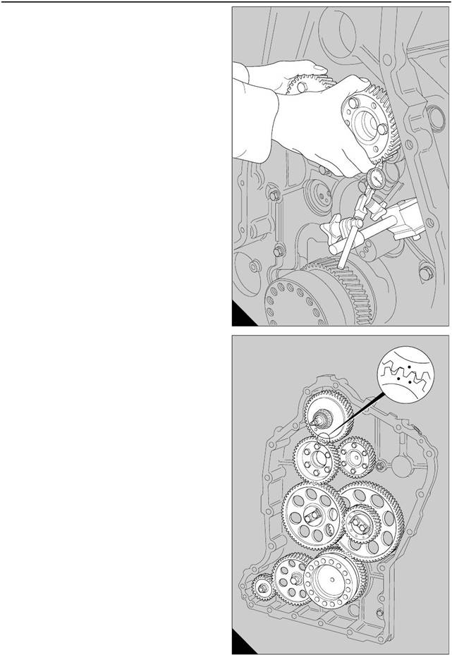
Check the backlash of the gears of the camshafts as
follows:
16 Put a dial test indicator with a magnetic base in the
timing case and set the button on the side of a tooth
of the camshaft gear of ’A’ bank (A). Hold stationary
the camshaft gear of ’B’ bank and rotate the camshaft
gear of ’A’ bank to the limit of its movement in both
directions. Check the reading on the dial test
indicator. Permissible backlash for the camshaft
gears is 0,100 to 0,250 mm (0.004 to 0.010 in).
Caution: To ensure that a correct reading is
obtained, it is important that the gear of ’B’ bank is not
allowed to move during this operation.
17 Remove the three temporary bolts from the
camshaft gear of ’A’ bank only. Apply ’Loctite 542’
hydraulic sealant to the threads of the six bolts which
retain the camshaft gear and fit the bolts, together
with plain washers, through the camshaft gear.
Tighten each bolt to 40 Nm (30 lbf ft).
Remove the three temporary bolts from the cams haft
gear of ’B’ bank and proceed:
18 Ensure that the two dowels which provide the
locations for the camshaft gears are toward the centre
line of the engine. Fit the drive gear of the fuel
injection pump/camshafts onto the extension of the
dowel of the ’B’ bank camshaft gear. Ensure that the
gears mesh c orrectly: the two timing marks of the
drive gear for the fuel injection pump/ camshafts with
the timing mark on the main idler gear (B). The two
timing marks on the drive gear of the fuel injection
pump/camshafts is then in the correct position to
receive the timing mark of the auxiliary drive gear.
Retain the drive gear of the fuel injection pump/
camshafts with three temporary bolts.
A
250
B
132
Perkins Engines Company Limited
96
This document has been printed from SPI². Not for Resale
 15
15
Caution:
Two extra sets of two timing marks are
provided, on the drive gear of the fuel injection pump/
camshafts, for the correct timing of two compressors
in the automotive applications only (A). Ensure that
the correct timing marks are aligned during the
assembly of the timing gears.
19 Put the dial test indicator in a suitable position and
set the button on one of the teeth of the drive gear of
the fuel injection pump/ camshafts. Hold the main
idler gear and check the reading for the bac klash of
the drive gear of the fuel injection pump/camshafts.
The permissible limits are 0,100 to 0,270 mm (0.004
to 0.011 in).
A
251
20 Remove the three temporary bolts from the drive
gear of the fuel injection pump/camshafts. Apply
’Loctite 241’ to the threads of the six bolts which retain
the drive gear and fit the bolts, with the plain washers,
in the drive gear. Tighten each bolt to 70 Nm (52 lbf
ft).
21 If relevant, fit the rocker boxes or pedestal rocker
assemblies, operation 12-5 or operation 12-2.
Assemble the auxiliary drive shaft as follows:
22 Fit the assembly of the auxiliary drive s haft in the
outer race of the inner roller bearing. The mesh of the
timing mark on the gear with the two timing marks on
the drive gear of the fuel injection pump must be
correct (A).
23 Fit the flywheel housing, operation 22-4.
24 Fit the housing for the oil seal of the auxiliary drive
shaft, with a complete pack of laminated shims, onto
the shaft and retain them with four bolts for early
engines, or six bolts for new engines, to the timing
case. Do not press in a new oil seal, if relevant, or the
Woodruff key of the drive shaft, during this operation.
25 Fit the special tool, VT15279, to the auxiliary drive
shaft and retain it with the nut from the c oupling
flange. Put a dial test indicator with a magnetic base
in the ’V’ of the crankc ase. Set the button of the dial
test indicator on one of the faces of the special tool
which is used as a datum. Turn the special tool to the
limit of its movement in both directions and check the
reading on the dial test indicator. The permissible
backlash is 0,10 to 0,33 mm (0.004 to 0.013 in).
Remove the special tool.
26 Move the dial test indicator to another suitable
position and check the axial movement of the
assembly of the auxiliary drive. The permissible end-
float is 0,076 to 0,127 mm (0.003 to 0.005 in). To
adjust the end-float, remove the housing of the oil seal
and reduce the thickness of the pack of the laminated
shims. Tighten the bolts which retain the housing of
the oil seal.
27 Chec k that the taper of the auxiliary drive shaft is
clean, press in a new oil seal if relevant, and press the
Woodruff key into its keyway. Fit the flange for the
drive coupling onto the shaft, followed by the plain
washer and the nut. Tighten the nut to the relevant
torque loads:
18 mm nut 200 Nm (148 lbf ft).
22 mm nut 300 Nm (220 lbf ft).
28 Fit the fuel injection pump, operation 20-11.
29 Press the ’Woodruff’ key for the cam into its
location in the outer end of the auxiliary drive shaft.
Slide the cam which drives the lift pump onto the drive
shaft, followed by the spring washer and the nut.
Tighten the nut to 54 Nm (40 lbf ft).
30 Fit the assembly of the mounting for the fuel lift
pump, operation 20-4.
31 Connect the delivery pipe for the lubricating oil
between the crankcase and the fuel lift pump.
32 Fit the guard of the auxiliary drive.
33 Connect the fuel pipes from the fuel lift pump and
the connection block for the spill fuel.
34 Fit the flywheel, operation 22-1.
35 Remove the engine from the build stand,
operation 16-1.
97
Perkins Engines Company Limited
This document has been printed from SPI². Not for Resale
![]()
![]()
![]() To clean and to inspect
To clean and to inspect
15-2
Auxiliary drive gear
15
1 Wash all the gears in kerosene, remove all the
deposits of thread locking compound and inspect the
teeth for wear.
Wear on the teeth is acceptable if there is no sign of
erosion, and if the backlash is within the permissible
To dismantle and to assemble
To dismantle
15-4
limits.
2 Test all the gears for cracks. Use the
electromagnetic method, if it is possible.
3 Check the bus hes and the axles of the idler gears
for wear. If suitable workshop facilities are available,
new bushes may be fitted to the idler gears. New
bushes are pre-finished and no further processes are
necessary after they have been fitted.
4 Inspect the thrust washers. The thrust washers
must be renewed if there is a reduction in the size of
the grooves in the thrust faces.
5 If it is necess ary to inspect the gears of the
lubricating oil pump, for early engines, the
lubricating oil sump and the sump adaptor must be
removed, operation 19-1 and operation 19-3
respec tively. For new engines, the single piece
sump must be removed, operation 19-5.
Double idler gear
1 For early engines, remove the six bolts which retain
the auxiliary drive gear and withdraw the gear from
the spigot of the auxiliary drive shaft.
To assemble
2 For early engines, put the gear on the spigot of the
shaft and, if necessary, fit the locating dowel.
3 Apply ’Loctite 241’ to the threads of the six bolts
which retain the gear and insert the bolts, with plain
washers, in the bolt holes of the gear.
4 Tighten evenly the bolts to a torque of 40 Nm (30
lbf ft).
To dismantle and to assemble
To dismantle
15-3
1 Release the 12 bolts from the large gear and
separate the two gears.
To assemble
If the bush of the gear needs to be renewed, it may be
an adv antage to do this while the two gears are
separated, operation 15-2.
1 Ensure that the two gears are clean and dry.
Fit in its correct position the larger gear on the spigot
of the small gear, and insert the dowel.
2 Apply ’Loctite 241’ to the threads of the 12 bolts
which hold together the assembly, and insert the
bolts, with plain washers, into the bolt holes.
3 Tighten each bolt to a torque of 40 Nm (30 lbf ft).
Perkins Engines Company Limited
98
This document has been printed from SPI². Not for Resale
 15
15
Timing case
To remove and to fit
Special tools:
2 temporary bolts, CV 13283
15-5
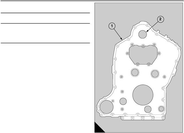
Note: The grade of bolts which retain the timing case
(A1) on the crankcase was changed in 1994. If the
timing case is removed from an engine with a build
line number before 12103, the bolts should be
renewed and the latest steel joint must be fitted. The
new bolts should be tightened to a torque of 135 Nm
(99.5 lbf ft). The five bolts which fit into the sump
should be tightened to 75 Nm (55 lbf ft).
To remove
1 Remov e the timing gears and the auxiliary drive
shaft, operation 15-1.
2 From the bolts which retain the timing case, remove
two bolts from the horizontally opposite sides of the
timing case. Make locally two guide studs and fit
them into the bolt holes.
3 Us e a hoist and a rope sling through the opening for
the auxiliary drive shaft (A2) to hold the timing case,
A
397
and remove the remainder of the bolts and the single
nut on early engines. Release carefully the timing
case from its dowels and lift it away from the
crankcase.
To fit
Caution: For new engines which have the steel joint,
CV14584, the bolts which fasten the timing case to
the crankcase and the sump are of a higher tensile
strength, and an additional bolt is fitted instead of the
stud. Also, the large dowel is retained by cap screws
instead of bolts.
1 Make locally a minimum of six suitable guide studs.
Degrease thoroughly the joint faces of the crankcase,
the timing case and the end of the sump, or the sump
adaptor as relevant, if it has not been removed. Fit
the guide studs into the bolt holes in the crankcase.
2 Apply a 5 mm bead of silicone sealant, ’Hylosil
RTV’, across the full width of each face where the joint
between the sump (or sump adaptor) and the
crankcase can be seen. Fit carefully a new joint onto
the guide studs and move it against the joint face.
Ensure that there is no distortion at the lower end of
the joint.
Note: Early engines were fitted with a fibre joint; the
new joint is made from steel and has a lay er of sealant
already applied.
3 Use the rope sling through the opening for the
auxiliary drive shaft (A2) to fit carefully the timing case
onto the guide studs. Release the rope sling and slide
the timing case up to the crankcase.
99
Perkins Engines Company Limited
This document has been printed from SPI². Not for Resale
 15
15
4 In sequence, remov e the guide studs and, for early
engines, fit ten bolts with spring washers into the bolt
holes. The three shorter bolts are fitted at the top. Fit
the thin nut and a spring washer onto the single stud.
Tighten the nut and the bolts finger tight. For new
engines fit eleven bolts, with spring washers, into the
bolt holes.
5 If the sump, or the sump adaptor as relevant, has
been removed, retain the lower end of the joint to the
timing cas e with two temporary bolts, plain washers
and nuts. Do not tighten the nuts.
6 If the sump, or the sump adaptor as relevant, has
not been removed, fit into the s ump (adaptor) the five
bolts. Do not tighten the bolts.
7 Put the large dowel into its rec ess, which is
machined in the end face of the crankcase. For early
engines, fit the two bolts and the two spring washers
(for new engines, two cap screws only) which retain
the dowel, and tighten temporarily. Do NOT fit spring
washers to the cap screws.
8 Fit the assembly of the axle and the distance piece
of the compound idler gear into its recess in the end
face of the crankcase. Retain temporarily the axle
with the outer thrust washer, and the two bolts.
9 For early engines, tighten evenly and gradually
the twelve bolts and the nut to 95 Nm (70 lbf ft). If the
sump (or sump adaptor) is fitted, tighten evenly and
gradually the five bolts (A9 to A13) to 55 Nm (40 lbf ft).
A
386
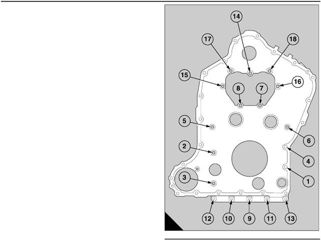
10 For new engines, fit the two temporary bolts CV
13283, with plain washers, into the crankcase,
through the bolt holes in the timing case normally
used for two of the flywheel housing bolts.
11 Use the sequence s hown (A); tighten gradually
To clean and to inspect
1 Clean the timing case, and also the fly wheel
15-6
the eleven bolts , the two cap screws and the two
temporary bolts to 135 Nm (100 lbf ft). If the sump (or
sump adaptor) is fitted, tighten also the five bolts (A9
to A13) to 75 Nm (55 lbf ft).
12 Remove the assembly of the axle and check that
it can be inserted again and turned in its recess
without interference. Adjust the position of the timing
case, if necess ary. Remove the two temporary bolts
before the flywheel housing is fitted.
13 Fit the timing gears and the auxiliary drive shaft,
operation 15-1.
housing, in a degreasing solution which is not caustic.
Remove all of the material of the old joint which
remains on the joint faces and check the joint faces
and the housings of the oil seals for damage.
2 Inspect the outer race of the inner roller bearing for
wear or erosion of the surface. If there are signs of
damage, renew the complete bearing and fit the outer
race of the new inner roller bearing to the bore of the
timing cas e.
Perkins Engines Company Limited
100
This document has been printed from SPI². Not for Resale
 15
15
Fits and clearances
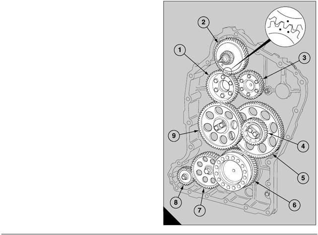
Backlash between gears
Camshaft gear - camshaft gear (A3)
Clearance (new). . . . . . . . . . . . . . . . . . . . . . . . . . . . . . . . . . . . . . . . . . . . . 0,10 to 0,25 mm (0.004 to 0.010 in)
Drive gear for fuel injection pump/camshafts (A1) - Auxiliary drive gear (A2)
Clearance (new). . . . . . . . . . . . . . . . . . . . . . . . . . . . . . . . . . . . . . . . . . . . . 0,10 to 0,33 mm (0.004 to 0.013 in)
Drive gear for fuel injection pump/camshafts (A1) - main idler gear (A9)
Clearance (new). . . . . . . . . . . . . . . . . . . . . . . . . . . . . . . . . . . . . . . . . . . . . 0,10 to 0,27 mm (0.004 to 0.011 in)
Main idler gear (A9) - double idler gear (A4)
Clearance (new). . . . . . . . . . . . . . . . . . . . . . . . . . . . . . . . . . . . . . . . . . . . . 0,10 to 0,27 mm (0.004 to 0.011 in)
Double idler gear (A5) - crankshaft gear (A6)
Clearance (new). . . . . . . . . . . . . . . . . . . . . . . . . . . . . . . . . . . . . . . . . . . . . 0,10 to 0,24 mm (0.004 to 0.009 in)
Crankshaft gear (A6) - idler gear for coolant pump (A7)
Clearance (new). . . . . . . . . . . . . . . . . . . . . . . . . . . . . . . . . . . . . . . . . . . . . 0,10 to 0,24 mm (0.004 to 0.009 in)
Idler gear for coolant pump (A7) - gear of coolant pump (A8)
Clearance (new). . . . . . . . . . . . . . . . . . . . . . . . . . . . . . . . . . . . . . . . . . . . . . . 0,10 to 0,28 mm (0.004 to 0.011)
A
132
101
Perkins Engines Company Limited
This document has been printed from SPI². Not for Resale