 English
 Espaol
 Franais
 阿拉伯
阿拉伯 中文
中文 Deutsch
 Italiano
 Português
 日本
日本 韩国
韩国 български
 hrvatski
 esky
esky Dansk
Dansk Nederlands
 suomi
suomi Ελληνικ
 印度
印度 norsk
norsk Polski
 Roman
Roman русский
 Svenska
Perkins3012柴油发动机威尔逊P850E柴油发电机配件交流充电发电机供应商,Perkins3012柴油发动机威尔逊P850E柴油发电机配件交流充电发电机技术价格规格咨询服务,Perkins3012柴油发动机威尔逊P850E柴油发电机配件交流充电发电机零配件供应,Perkins3012柴油发动机威尔逊P850E柴油发电机配件交流充电发电机售后服务中心,Perkins3012柴油发动机威尔逊P850E柴油发电机配件交流充电发电机,Perkins3012柴油发动机威尔逊P850E柴油发电机配件交流充电发电机详细的技术参数,

产品中心
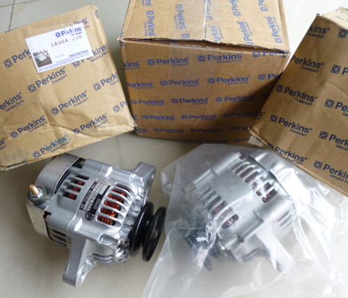
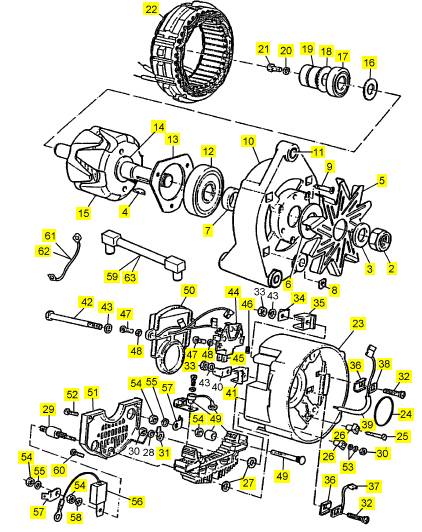
Perkins3012柴油发动机威尔逊P850E柴油发电机配件交流充电发电机
详细描述
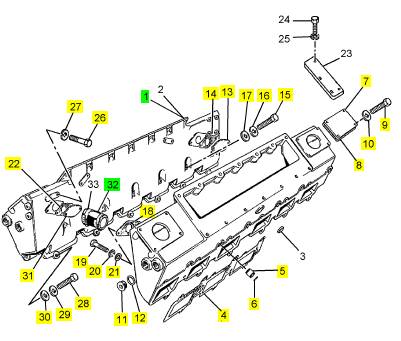
项目 零配件号码 最近的部分号码 描述
1 CV12081/2 2 CV12081/2 进气岐管
4 CV20233 4 CV20233 密封垫 - IND 的岐管
5 CV507 12 CV507 线桥
6 ST10928 24 ST10928 密封O型圈
7 CV12997 2 CV12997 切片板
8 CV19492 2 CV72491 密封垫
9 2314 C045 4 2314 C045 固定螺钉
10 2134 A008 4 2134 A008 垫圈
11 ST20133 8 ST20133I 栓塞
12 ST49891 8 ST49891 垫圈
13 CV13201 2 CV13201 切片板 U11497X
14 CV20379 2 CV20379 密封垫 U11497X
15 ST43563 12 ST43563 螺拴
16 2134 A010 12 2134 A010 垫圈
17 2131 A010 12 2131 A010 垫圈
18 CV20379 1 CV20379 密封垫 U11497X
19 2314 C045 8 2314 C045 固定螺钉 U11497X
20 2134 A008 8 2134 A008 垫圈 U11497X
21 2131 A008 8 2131 A008 垫圈 U11497X
22 CV20379 1 CV20379 密封垫 U11497X
26 ST44452 2 ST44452 固定螺钉
27 ST49940 2 ST49940 垫圈
28 2314 C053 28 2314 C053 螺旋
29 2134 A010 28 2134 A010 垫圈
30 2131 A010 28 2131 A010 垫圈
31 CV13201 2 CV13201 切片板 U11497X U9736W
32 U5MH0050 1 U5MH0050 水管装备 U9735W
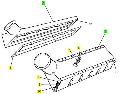
项目 零配件号码 最近的部分号码 描述
1 CV13851 1 CV13851 进气岐管
3 CV20211 2 CV20211I 密封垫
4 CV13852 1 CV13852 进气岐管
6 ST20133 2 ST20133I 栓塞
7 ST49891 2 ST49891 垫圈
8 2314 C045 28 2314 C045 固定螺钉
9 2134 A008 28 2134 A008 垫圈
10 2131 A008 28 2131 A008 垫圈
项目 零配件号码 最近的部分号码 描述
1 OD20798 1 CV70291 交流充电发电机
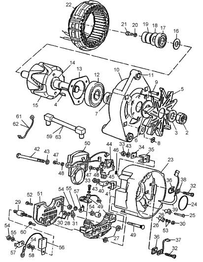
项目 零配件号码 最近的部分号码 描述
2 OD20441 1 OD20441 螺帽
3 OD21655 1 OD21655 垫圈
3 OD17226 1 OD21655 垫圈
4 OD17253 1 OD17253 键
5 OD19835 1 OD19835 风扇
6 OD19797 1 OD19797 垫圈
7 OD20543 1 OD20543 距离块
8 OD20838 4 OD20838 螺帽
9 OD20839 3 OD20839 螺旋
10 OD20841 1 OD20841 壳
11 OD20840 1 OD20840 衬套
12 OD19798 1 OD19798 滚珠瓦
13 OD20842 1 OD20842 承件
14 OD20843 1 OD20843 距离块
15 OD19800 1 OD19800R 转子
(15) OD19800R 1 OD19800R 转子
16 OD20844 1 OD20844 距离块
17 OD19799 1 OD19799 滚珠瓦
18 OD20845 1 OD20845 转向装置
19 OD20846 1 OD20846 圈
20 OD20847 1 OD20847 垫圈
21 OD20848 1 OD20848 螺旋
22 OD19778 1 OD19778 固定子
23 OD20895 1 OD20895 壳
24 OD20849 1 OD20849 密封O型圈
25 OD20850 2 OD20850 螺旋
26 OD20851 2 OD20851 绝缘体
27 OD20852 2 OD20852 间隔器
28 OD20847 1 OD20847 垫圈
29 OD20854 2 OD20854 终点
30 OD20855 2 OD20855 螺帽
31 OD20856 1 OD20856 终点
32 OD20857 2 OD20857 终点
33 OD19784 2 OD19784 螺帽
34 OD20858 1 OD20858 终点
35 OD20859 1 OD20859 守卫
36 OD20860 2 OD20860 终点
37 OD20861 1 OD20861 缆
38 OD20862 1 OD20862 缆
39 OD20863 1 OD20863 鞘
40 OD20864 1 OD20864 终点
41 OD20866 1 OD20866 守卫
42 OD20867 4 OD20867 螺拴
43 OD19785 6 OD19785 垫圈
44 OD20868 1 OD20868 夹持工具
45 OD19442 2 OD19442 刷
46 OD20869 2 OD20869 弹簧
47 OD20870 4 OD20870 螺旋
48 OD20847 4 OD20847 垫圈
49 OD20871 1 OD20871 整流器
50 OD20896 1 OD20896 调整器
51 OD20872 1 OD20872 盖
52 OD20873 2 OD20873 螺旋
53 OD20874 2 OD20874 垫圈
54 OD20875 4 OD20875 螺帽
55 OD20876 3 OD20876 垫圈
56 OD20877 1 OD20877 电容器
57 OD20878 2 OD20878 终点
58 OD20879 2 OD20879 垫圈
59 OD20880 1 OD20880 振动乘用马
60 OD20881 1 OD20881 螺旋
61 OD20897 1 OD20897 缆
62 OD20898 1 OD20898 鞘
63 OD20899 1 OD20899 衬套
 Crankshaft gear - idler gear for lubricating oil pump
15
Clearanc e (new) . . . . . . . . . . . . . . . . . . . . . . . . . . . . . . . . . . . . . . . . . . . . 0,10 to 0,20 mm (0.004 to 0.008 in)
Idler gear for lubricating oil pump - gear of lubricating oil pump
Clearanc e (new) . . . . . . . . . . . . . . . . . . . . . . . . . . . . . . . . . . . . . . . . . . . . 0,10 to 0,39 mm (0.004 to 0.015 in)
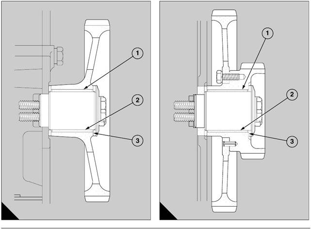
Idler gears on axles
Main idler gear (A)
Bore of gear (new) (A1). . . . . . . . . . . . . . . . . . . . . . . . . . . . . . . . . 50,000 to 50,025 mm (1.9685 to 1.9695 in)
Diameter of bush (new) . . . . . . . . . . . . . . . . . . . . . . . . . . . . . . . . . 50,089 to 50,127 mm (1.9720 to 1.9735 in)
Interference (new) . . . . . . . . . . . . . . . . . . . . . . . . . . . . . . . . . . . . . . . 0,064 to 0,127 mm (0.0025 to 0.0049 in)
Bore of bush (new) (A2) . . . . . . . . . . . . . . . . . . . . . . . . . . . . . . . . 44,983 to 45,034 mm (1.7709 to 1.7729 in)
Axle diameter (new). . . . . . . . . . . . . . . . . . . . . . . . . . . . . . . . . . . . 44,910 to 44,950 mm (1.7681 to 1.7697 in)
Clearance (new) . . . . . . . . . . . . . . . . . . . . . . . . . . . . . . . . . . . . . . . . 0,033 to 0,124 mm (0.0013 to 0.0048 in)
Permissible worn clearance. . . . . . . . . . . . . . . . . . . . . . . . . . . . . . . . . . . . . . . . . . . . . . . 0,199 mm (0.0078 in)
Double idler gear (B)
Bore of gear (B1) . . . . . . . . . . . . . . . . . . . . . . . . . . . . . . . . . . . . . . 50,000 to 50,025 mm (1.9685 to 1.9695 in)
Diameter of bush . . . . . . . . . . . . . . . . . . . . . . . . . . . . . . . . . . . . . . 50,089 to 50,127 mm (1.9720 to 1.9735 in)
Interference (new) . . . . . . . . . . . . . . . . . . . . . . . . . . . . . . . . . . . . . . . 0,064 to 0,127 mm (0.0025 to 0.0049 in)
Bore of bush (B2) . . . . . . . . . . . . . . . . . . . . . . . . . . . . . . . . . . . . . 44,983 to 45,034 mm (1.7709 to 1.7729 in)
Diameter of axle . . . . . . . . . . . . . . . . . . . . . . . . . . . . . . . . . . . . . . 44,910 to 44,950 mm (1.7681 to 1.7697 in)
Clearance (new) . . . . . . . . . . . . . . . . . . . . . . . . . . . . . . . . . . . . . . . . 0,033 to 0,124 mm (0.0013 to 0.0048 in)
Permissible worn clearance. . . . . . . . . . . . . . . . . . . . . . . . . . . . . . . . . . . . . . . . . . . . . . . 0,199 mm (0.0078 in)
A
144
B
145
Perkins Engines Company Limited
102
This document has been printed from SPI². Not for Resale
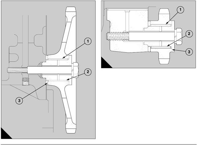 15
15
Idler gear for coolant pump (A)
Bore of gear (A1) . . . . . . . . . . . . . . . . . . . . . . . . . . . . . . . . . . . . . . 34,000 to 34,025 mm (1.3385 to 1.3395 in)
Diameter of bush . . . . . . . . . . . . . . . . . . . . . . . . . . . . . . . . . . . . . . 34,087 to 34,125 mm (1.3420 to 1.3435 in)
Interference (new) . . . . . . . . . . . . . . . . . . . . . . . . . . . . . . . . . . . . . . . 0,062 to 0,125 mm (0.0024 to 0.0049 in)
Bore of bush (A2). . . . . . . . . . . . . . . . . . . . . . . . . . . . . . . . . . . . . . 29,985 to 30,112 mm (1.1805 to 1.1855 in)
Diameter of axle. . . . . . . . . . . . . . . . . . . . . . . . . . . . . . . . . . . . . . . 29,947 to 29,960 mm (1.1790 to 1.1795 in)
Clearance (new). . . . . . . . . . . . . . . . . . . . . . . . . . . . . . . . . . . . . . . . . . . 0,025 to 0,165 mm (0.001 to 0.006 in)
Idler gear for oil pump (B)
Bore of gear (B1) . . . . . . . . . . . . . . . . . . . . . . . . . . . . . . . . . . . . . . 34,000 to 34,025 mm (1.3385 to 1.3395 in)
Diameter of bush . . . . . . . . . . . . . . . . . . . . . . . . . . . . . . . . . . . . . . 34,087 to 34,125 mm (1.3420 to 1.3435 in)
Interference (new) . . . . . . . . . . . . . . . . . . . . . . . . . . . . . . . . . . . . . . . 0,062 to 0,125 mm (0.0024 to 0.0049 in)
Bore of bush (B2). . . . . . . . . . . . . . . . . . . . . . . . . . . . . . . . . . . . . . 29,985 to 30,112 mm (1.1805 to 1.1855 in)
Diameter of axle. . . . . . . . . . . . . . . . . . . . . . . . . . . . . . . . . . . . . . . 29,947 to 29,960 mm (1.1790 to 1.1795 in)
Clearance (new). . . . . . . . . . . . . . . . . . . . . . . . . . . . . . . . . . . . . . . . . . . . . 0,025 to 0,165 mm (0.001 to 0.006)
B
147
A
146
103
Perkins Engines Company Limited
This document has been printed from SPI². Not for Resale
End float of idler gears
Refer to the illustrations (A and B) on page 102.
Main idler gear (A)
15
Length of axle . . . . . . . . . . . . . . . . . . . . . . . . . . . . . . . . . . . . . . . . 56,150 to 56,200 mm (2.2106 to 2.2126 in)
Width of hub (A3). . . . . . . . . . . . . . . . . . . . . . . . . . . . . . . . . . . . . . 50,875 to 51,000 mm (2.0029 to 2.0079 in)
Thicknes s of thrust washers . . . . . . . . . . . . . . . . . . . . . . . . . . . . . . . . . . . . . 2,450 to 2,500 (0.0965 to 0.0984
Clearance (new) . . . . . . . . . . . . . . . . . . . . . . . . . . . . . . . . . . . . . . . . . *0,100 to 0,425 mm (*0.004 to 0.017 in)
Double idler gear (B)
Length of axle . . . . . . . . . . . . . . . . . . . . . . . . . . . . . . . . . . . . . . . . 56,150 to 56,200 mm (2.2106 to 2.2126 in)
Width of hub (B3). . . . . . . . . . . . . . . . . . . . . . . . . . . . . . . . . . . . . . 50,875 to 51,000 mm (2.0029 to 2.0079 in)
Thicknes s of thrust washers . . . . . . . . . . . . . . . . . . . . . . . . . . . . . . . 2,450 to 2,500 mm (0.0965 to 0.0984 in)
Clearance (new) . . . . . . . . . . . . . . . . . . . . . . . . . . . . . . . . . . . . . . . . . *0,100 to 0,425 mm (*0.004 to 0.017 in)
* These dimensions are relevant if the thrust
was hers are not completely flat
Caution: The thrust washers must be renewed if there is a reduction in the size of the grooves in the thrust
faces and the depths of the grooves are less than the nominal depth of 0,18 to 0,38 (0.007 to 0.015 in).
Refer to the illustrations (A and B) on page 103.
Idler gear of coolant pump (A)
Length of axle . . . . . . . . . . . . . . . . . . . . . . . . . . . . . . . . . . . . . . . . 35,200 to 35,300 mm (1.3858 to 1.3897 in)
Width of hub (A3). . . . . . . . . . . . . . . . . . . . . . . . . . . . . . . . . . . . . . 32,450 to 32,500 mm (1.2775 to 1.2795 in)
Thickness of thrust washer . . . . . . . . . . . . . . . . . . . . . . . . . . . . . . . . 2,450 to 2,500 mm (0.0965 to 0.0984 in)
Clearance (new) . . . . . . . . . . . . . . . . . . . . . . . . . . . . . . . . . . . . . . . . 0,200 to 0,400 mm (0.0078 to 0.0157 in)
Idler gear of lubricating oil pump (B)
Length of axle . . . . . . . . . . . . . . . . . . . . . . . . . . . . . . . . . . . . . . . . 35,200 to 35,300 mm (1.3858 to 1.3897 in)
Width of hub (B3). . . . . . . . . . . . . . . . . . . . . . . . . . . . . . . . . . . . . . 32,450 to 32,500 mm (1.2775 to 1.2795 in)
Thickness of thrust washer . . . . . . . . . . . . . . . . . . . . . . . . . . . . . . . . 2,450 to 2,500 mm (0.0965 to 0.0984 in)
Clearance (new) . . . . . . . . . . . . . . . . . . . . . . . . . . . . . . . . . . . . . . . . 0,200 to 0,400 mm (0.0078 to 0.0157 in)
Perkins Engines Company Limited
104
This document has been printed from SPI². Not for Resale
16
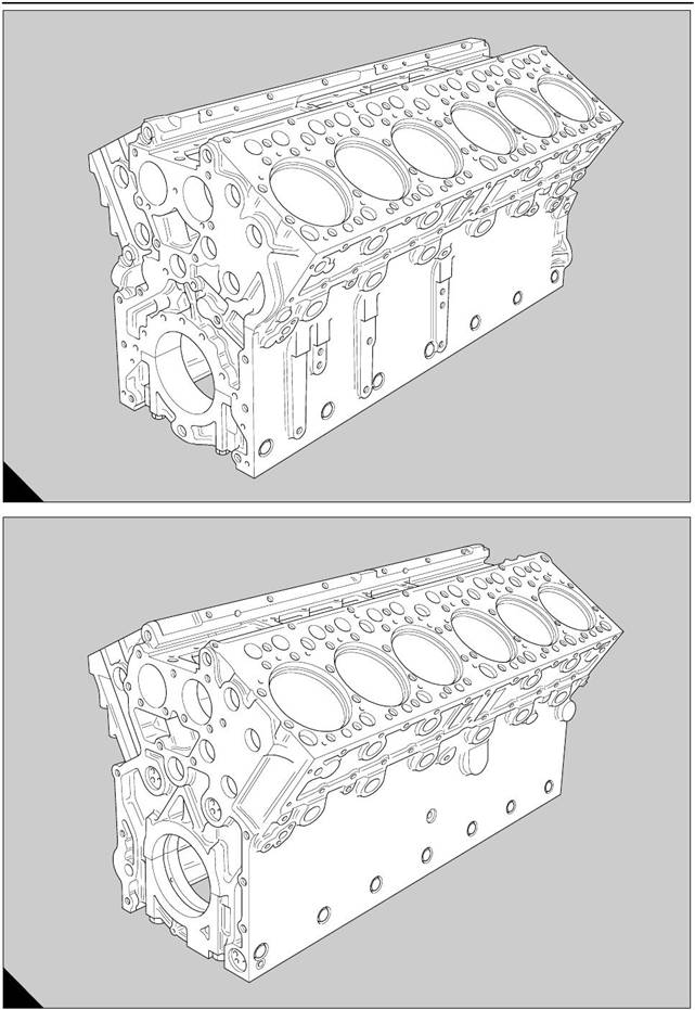
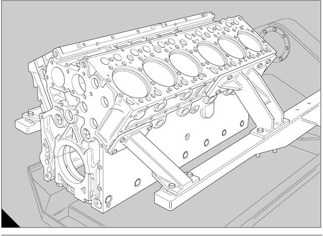
Crankcase and cylinder liners
General description
16
The crankcase (A and B) is a monobloc casting made
from high quality cast iron. The casting is dipped in a
special sealing compound to prevent contamination
and to seal all surfaces which are not machined. The
first illustration (A) shows the front of the crankcase
and the second illustration (B) shows the rear of the
crankcase.
The top of the crankcase has two banks of six
cy linders which make a ’V’ arrangement at an
included angle of 60 degrees. The cylinder banks are
not symmetrical on the crankcase and ’B’ bank is
nearer to the front of the engine. The bores of the
cy linders are machined to receive dry cylinder liners.
Galleries in the casting of the cylinder block supply a
flow of coolant around each c ylinder bore. Small
holes are drilled through each flame face to supply
coolant to the cylinder heads.
The crankcase has housings for seven main
bearings. Each assembly of the main bearings is
retained by a bearing cap made from a steel forging.
The bearing c aps at the centre and at each end of the
engine are fitted with four bolts. Each of the remainder
of the bearing caps are assembled with two bolts.
To ensure that the bearing caps are rigid, side bolts
are fitted through the side walls of the crankcase into
location pads on each side of the bearing caps. All oil
galleries are drilled to ensure that the bores are
accurate and clean.
The twelve dry liners are a fine clearance fit in the
crankcase. They have flanges at the upper ends and
are retained in their respective cylinder bores by the
four cylinder heads.
Each liner is made of cast iron by a centrifugal
process. The degree of hardness is varied along its
length and the internal diameter is machined by
special processes to obtain a surface finish which will
reduce wear and consumption of oil. The upper face
of each bank of cylinders has bores for 24 tappets.
The camshaft bearings are rolled bushes, of the split
type, and are pre-finished. They have steel bac ks
and bearing surfac es of lead bronze. The bearings do
not need normally a special procedure except to
ensure that they are cleaned thoroughly during the
overhaul.
Perkins Engines Company Limited
105
This document has been printed from SPI². Not for Resale
 16
16
A
254
B
255
Perkins Engines Company Limited
106
This document has been printed from SPI². Not for Resale
![]()
|
Crankcase
a build stand
Special tools:
Strap wrench, 21825 825
16-1
7 Disconnect and remove the exhaust pipes.
8 Disconnect the electrical system between the stop
solenoid, the coolant temperature switch and the oil
pressure switch, and the main control panel.
9 Remove the radiator, operation 21-1.
10 Fit the lift plate CV 8012 to the flywheel housing
with two bolts and the spring washers.
11 Use the universal lift adaptor VP 8364 and a
suitable hoist to hold the assembly of the engine.
Build stand - engine VP 5908 which also includes:
Mounting brackets - crankcase
’B’ bank rear VP 5597
’A’ bank rear VP 5598
’A’ bank front VP 6836
’B’ bank front VP 6837
Universal lift adaptor VP 8364
Lift plate CV 8012
To fit to a build stand
To obtain access to the crankcase and further main
components, the engine must be disconnected from
its driven unit and fitted in a build stand. Instructions
to disconnect the driven unit are to be found in the
publication of the relevant manufacturer. To fit the
engine in a build stand, proceed as follows:
1 Disconnect the batteries.
2 Close the valves and disconnect the pipes for the
fuel supply and the fuel return. Remove and discard
the two filter canisters.
3 To drain the cooling system, remove the drain plugs
from the radiator, from the outlet pipe of the coolant
pump, from the front of ’A’ bank and from the rear of
’B’ bank of the crankcase.
4 Drain the lubricating oil from the engine by the
removal of the drain plug from the base of the sump.
5 Drain the engine lubricating oil from the heat
exchanger by the removal of the drain plug at the rear
end. Put a container below the filter canisters to
receive the oil which drains from the heat exchanger.
6 Lubricating oil which remains in the heat exchanger
can be drained by the removal of the three filter
canisters. Use the strap wrench, 21825 825, to
remov e and discard the filter canisters.
12 Disconnect the support brackets from the flywheel
housing, and the front mountings from the base
frame.
If not relevant to the job, the front mountings may be
retained on the fan adaptor.
13 Lift the assembly of the engine from the mountings
and lower it on to the floor of the workshop with
suitable wooden supports beneath the flywheel
housing.
Before the engine is fitted in the build stand and
subsequently dismantled, clean it thoroughly and
ensure that the cooling and lubrication systems are
drained completely.
14 Remove the air filters and their support brackets,
and the inlet ducts for the turbochargers.
15 If relevant to the job, releas e the three bolts which
retain the starter motor. Withdraw the starter motor.
16 Remove the fan, operation 21-8.
17 If relevant to the job, remove the fan belts and the
tensioner pulley, operation 21-9.
18 If relevant to the job, remove the crankshaft pulley,
the damper and the alternator pulley, operation 14-1.
Caution: The damper is a heavy component and
must not be allowed to fall during removal, because
distortion of the casing can prevent its correct
operation.
107
Perkins Engines Company Limited
This document has been printed from SPI². Not for Resale
 19 Remove the front covers of the coolant galleries
and fit the four mounting brackets to the crankcase as
To remove from a build stand
16
follows:
l VP 6836:
l VP 6837:
l VP 5598:
l VP 5597:
at the front of ’A’ bank over the front
coolant gallery
at the front of ’B’ bank over the front
coolant gallery
on the bosses at the rear of ’A’ bank
on the bosses at the rear of ’B’ bank
1 If relevant, fit the lift plate CV 8012 to the flywheel
housing with two bolts and spring washers.
2 Remove the eight bolts and nuts, whic h retain the
mounting brackets to the arms of the build stand, and
use the universal lift adaptor VP 8364 and a suitable
hoist to remove the engine from the build stand.
Lower the engine on to the floor of the workshop with
suitable wooden s upports beneath the flywheel
housing.
Caution: Ensure that the plug in the boss at the rear
of ’A’ bank has been removed before the mounting
bracket VP 5598 is fitted.
20 Use the lift adaptor VP 8364 to put the engine in
the build stand VP 5908 with the flywheel at the outer
end. Fit the eight bolts, which retain the mounting
brackets, through the arms of the build stand as
shown (A), fit the nuts and tighten sec urely. Remove
the universal lift adaptor.
3 Clean thoroughly the blanking plug which was
removed from the rear of ’A’ bank. Apply some
’Loc tite 542’ to the blanking plug and ensure that it is
fitted to the boss when the mounting bracket VP 5598
is removed.
4 Remove the four mounting brackets from the
crankcase and use new joints to fit the front covers of
the coolant galleries.
5 If relevant, fit the crankshaft pulley, the damper and
the alternator pulley, operation 14-1.
A
256
Perkins Engines Company Limited
108
This document has been printed from SPI². Not for Resale
|
6 If relevant, fit the assembly of the tensioner pulley
and fit loosely the fan belts, operation 21-9.
7 Fit the fan and tighten the fan belts, operation 21-9.
8 If relevant, fit the front mountings to the fan adaptor.
9 Fit the starter motor and retain it with the three
bolts.
10 Fit the inlets of the turbochargers, the air filters
and their support brackets.
11 Use the universal lift adaptor VP 8364 to lift the
assembly of the engine over the base frame and
lower carefully the engine. Connect the support
brackets to the flywheel housing and the front
mountings to the base frame. Remove the lift
adaptor.
12 Fit the radiator, operation 21-1.
13 Connect the electrical system between the main
control panel and the stop solenoid, the coolant
temperature switch and the oil pressure switch.
14 Install and connect the exhaust pipes.
15 Fit the drain plugs in the base of the lubricating oil
sump and at the rear end of the heat exchanger.
16 Fill the filter canisters with clean engine lubricating
oil and fit them on to the adaptors of the bracket for
the filter head, until the seal on each canister is just in
contact with its face. Tighten by hand each canister a
further 1 /4 turns. Do NOT overtighten.
17 If the engine lubricating oil can be used again,
return it to the sump of the engine and fill the sump
with new and clean oil to the ’Full’ mark on the
dipstick, if necessary.
|
|
bank and to the rear of ’B’ bank of the crankcase, to
the outlet pipe of the coolant pump and to the radiator.
Check that the drain plugs are secure and fill the
cooling system. Add more coolant, of the same
specification as that already in use, if neces sary.
Check for leakage in the system.
19 Fit two new fuel filter canisters on to the adaptors
of the filter head, until the seal on each canister is just
in contact with its face. Tighten by hand each canister
the pipes and open the valves for the fuel supply and
the fuel return. Check for leakage in the sys tem.
20 Release the two bolts and the spring washers
which retain the lift plate CV 8012 on the flywheel
housing and remove the lift plate.
21 Connect the engine to its driven unit, in
accordance with the instructions which are to be
found in the publication of the relevant manufacturer.
22 Connect the batteries.
109
Perkins Engines Company Limited
This document has been printed from SPI². Not for Resale
![]() To dismantle and to assemble
To dismantle and to assemble
16-2
11 Remove the fan adaptor, operation 21-10.
16
Special tools:
Retainers, 21825 844
Lift adaptor – crankcase
VP 9967 Dial gauge and holder, 21825 786
Check plate, 21825 787
To dismantle
1 Fit the assembly of the engine in the build stand,
operation 16-1.
It is recommended that the smaller items, (for
example, low-pressure fuel pipes, clips, brackets ,
etc.) have labels to indicate their location and their
purpose, and are put in containers with relevant
engine parts.
2 Disconnect and remove the coolant pipes from
between the coolant gallery of 'A' bank, the coolant
pump and the heat exchanger.
3 Disconnect and remove the coolant pipe from
between the front cover of the coolant gallery on 'B'
bank and the outlet of the heat exchanger.
4 Disconnect and remove the pipe between the
coolant pump and the thermos tat housings.
5 Remove the fuel injectors, operation 20-7.
6 Remove the fuel injection pump, operation 20-8.
7 Remove the cylinder heads, operation 12-9.
8 Remove the two blanking plates and the mounting
for the fuel injection pump from the 'V' of the
crankcase.
9 Lift out the tappets and make temporary marks to
indicate their positions when the crankcase is
assembled.
10 Hold the cylinder liners with the retainers, 21825
844.
12 Remove the flywheel and the flywheel housing,
operation 22-4.
13 Remove the timing case, operation 15-5.
14 Remove the camshafts, operation 17-1.
15 Remove the lubricating oil sump, operation 19-1
or, for new engines, operation 19-5.
16 For early engines, remove the sump adaptor,
operation 19-3.
17 Remove the lubricating oil pump, operation 19-7.
18 Remove the assemblies of the pistons and the
connecting rods, operation 13-3 paragraph 8.
19 Remove the crankshaft, operation 14-4 paragraph
12 to 14.
20 Remove the piston cooling jet assemblies.
21 Remove the retainers. Withdraw carefully each
liner and put it with its own assembly of piston and
connecting rod.
22 Remove the rear covers of the coolant galleries,
the fuel filter head, operation 20-3, and the heat shield
for the filter head.
23 If the camshaft bearings are to be renewed, the
cup plugs at the front ends of the camshaft bores
must be removed.
24 If the crankcase is to be tested under pressure,
remove the eight bolts and nuts, which retain the
mounting brackets to the arms of the build stand. Use
a hoist and a suitable rope sling to remove the
crankcas e from the build stand.
25 Remove the four mounting brackets from the
crankcas e.
Perkins Engines Company Limited
110
This document has been printed from SPI². Not for Resale
 16
16
To assemble
1 If the crankcase has been tested under pressure
and it is acceptable, fit the four mounting brack ets to
the crankcase. Use a hoist and a suitable rope sling
to lift the crankcase and put it in the build stand VP
5908. Ensure that the end of the crankcase to which
the timing case is fitted is furthest from the build
stand.
Note: The weight of the crankcase is approximately
620 kg (1367 lb).
2 Fit each piston cooling jet assembly onto the
relevant studs in the crankcase, fit the spring washers
and nuts on the studs and lightly tighten the nuts.
A
257
Caution:
Check that the top faces of the banks of the
cylinders and all of the cylinder liners are clean. The
number of its respective cylinder is etched on each
cylinder liner, and the numbers should be toward the
centre of the engine when the cylinder liners are
ins erted.
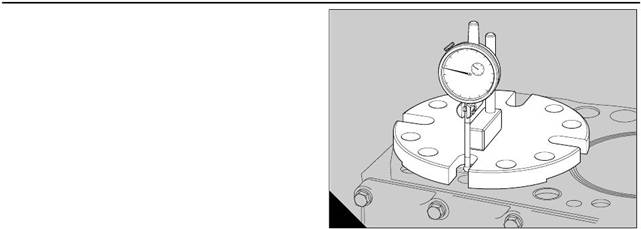
3 Insert each cylinder liner in its respective cylinder
bore. Use the check plate, 21825 786, and the dial
gauge and holder, 21825 787, to check the protrusion
of the cylinder liners above the top faces of both
banks of cylinders. Ensure that the check plate and
the holder for the dial gauge are clean.
4 Put the check plate over the first cylinder liner and
put the holder of the dial gauge on the checking plate.
Put the button of the dial gauge on the top face of the
bank of cylinders and set the dial gauge to zero (A).
Caution: The check plate may be held on the top
face of the bank of cylinders by two of the bolts which
retain a cylinder head, if the top face is not horizontal.
111
Perkins Engines Company Limited
This document has been printed from SPI². Not for Resale
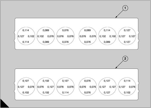 5 Put carefully the button of the dial gauge onto the
top face of the flange of the first cylinder liner, at four
different locations. Each correct location for the
button is shown (A). Make a note of the deflection,
from zero, for each location.
6 Move the check plate to the other cylinder liners in
rotation and check their protrusions. Compare the
readings which have been obtained with the
protrusions shown (A).
Caution:
l The protrusion for each cylinder liner must be
between 0,076 mm and 0,127 mm (0.003 in and
0.005 in).
l The variation of protrusion around the
circumference of a liner must not exceed 0,025
mm (0.001 in).
l The variation of protrusion between the nearest
points of two cylinder liners which are next to each
other must not exceed 0,025 mm (0.001 in).
l The maximum difference in the protrusions under
one cylinder head must not exceed 0.051 mm
(0.002 in).
l Banks shown as A1 will be acceptable. Banks
shown as A2 are not acceptable.
16
7 Renew a cylinder liner if its protrusion is not correct.
Inspect the seat of the flange of the new cylinder liner,
operation 16-5. Check its protrusion also.
8 When their protrusions have been checked, make
temporary marks to indicate the exact position of each
flange in the crankcase and remove the cylinder
liners. Immediately before the work proceeds, clean
the top of each bank of cylinders, degrease and dry
the cylinder liners and the recesses for the flanges of
the cylinder liners.
9 Apply a bead of ’Hylomar PL 32/M’ (medium grade)
to the seat under the flange of each c ylinder liner.
Remove the surplus from the faces on the side. Allow
the compound to partially dry, align the temporary
marks and insert, without rotation, each cylinder liner
in its bore in the crankcase. Do not subsequently
allow the ’Hylomar’ seal to be broken.
10 Use the bolts of the cylinder heads to fit eight
retainers, 21825 844, to ensure that the cylinders
liners remain in their positions when the assemblies of
the pistons and the connecting rods are fitted.
A
130
Perkins Engines Company Limited
112