 English
 Espaol
 Franais
 阿拉伯
阿拉伯 中文
中文 Deutsch
 Italiano
 Português
 日本
日本 韩国
韩国 български
 hrvatski
 esky
esky Dansk
Dansk Nederlands
 suomi
suomi Ελληνικ
 印度
印度 norsk
norsk Polski
 Roman
Roman русский
 Svenska
Perkins2806柴油发动机威尔逊P700E柴油发电机配件CH12434燃料过滤器供应商,Perkins2806柴油发动机威尔逊P700E柴油发电机配件CH12434燃料过滤器技术价格规格咨询服务,Perkins2806柴油发动机威尔逊P700E柴油发电机配件CH12434燃料过滤器零配件供应,Perkins2806柴油发动机威尔逊P700E柴油发电机配件CH12434燃料过滤器售后服务中心,Perkins2806柴油发动机威尔逊P700E柴油发电机配件CH12434燃料过滤器,Perkins2806柴油发动机威尔逊P700E柴油发电机配件CH12434燃料过滤器详细的技术参数,

产品中心
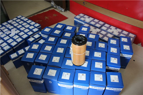
Perkins2806柴油发动机威尔逊P700E柴油发电机配件CH12434燃料过滤器
详细描述
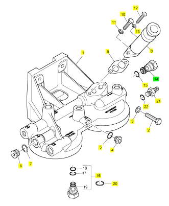
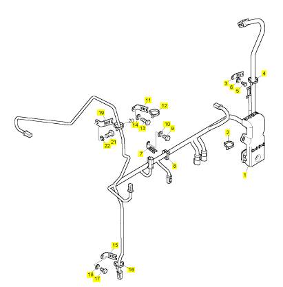
项目 零配件号码 新件号 描述
1 CH12434 1 CH12434 燃料过滤器
1 CH11075 1 CH12434 燃料过滤器
2 CH10609 1 CH10609 螺拴
3 CH10255 1 CH10255 垫圈
3 CH10541 1 CH10255 垫圈
4 CH10286 1 CH10286 栓塞
5 CH11880 1 CH11880 密封O型圈
5 CH10046 1 CH10046 密封O型圈
6 CH10287 1 CH10287 栓塞
7 T406205 1 T406205 密封O型圈
7 CH10048 1 CH10048 密封O型圈
8 CH10439 1 CH10439 汽酒共腾泵
9 CH10008 1 CH10008 密封垫
10 CH10557 1 CH10557 螺拴
11 CH10277 1 CH10277 垫圈
11 CH10131 1 CH10131 密封O型圈
12 CH10848 1 CH10848 螺拴
13 CH10086 1 CH10086 垫圈
14 CH10836 1 CH10836 阀
15 T400188 1 T400188 密封O型圈
16 CH12017 1 CH12017 非回路阀
16 CH10457 1 检查历史 阀
16 CH12017 1 CH12017 非回路阀
20 CH10131 1 CH10131 密封O型圈
21 CH11410 1 CH11410 栓塞
22 CH11880 1 CH11880 密封O型圈
23 CH11411 1 CH11411 灰尘盾
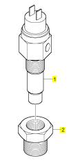
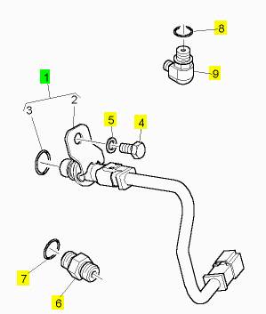
项目 零配件号码 新件号 描述
1 CH12893 1 CH12893 温度感应传感器
1 CV18338/5 1 CH12893 温度感应传感器
2 OE51375 1 OE51375 承接器
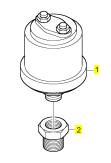
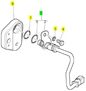
项目 零配件号码 新件号 描述
1 CH12894 1 CH12894 油压寄件人
1 CV18339/2 1 CH12894 油压寄件人
2 CH11138 1 CH11138 承接器
项目 零配件号码 新件号 描述
1 CH11985 1 CH11985 线束
2 CH11981 1 CH11981 缆拉杆
3 CH10071 2 T410794 夹
4 CH10054 2 CH10054 缆拉杆
5 CH10794 2 CH11897 螺拴
6 CH10541 2 CH10255 垫圈
7 CH10799 2 CH10799 夹
8 CH10054 2 CH10054 缆拉杆
9 CH10797 2 CH10797 螺拴
10 CH10100 2 CH10100 垫圈
11 CH10072 1 CH10072 夹
12 CH10054 1 CH10054 缆拉杆
13 CH10537 1 CH11895 螺拴
14 CH10541 1 CH10255 垫圈
15 CH10072 2 CH10072 夹
16 CH10054 2 CH10054 缆拉杆
17 CH10794 2 CH11897 螺拴
18 CH10541 2 CH10255 垫圈
19 CH10072 1 CH10072 夹
20 CH10054 1 CH10054 缆拉杆
21 CH10796 1 CH10796 螺拴
22 CH10277 1 CH10277 垫圈
项目 零配件号码 新件号 描述
CH10867 1 CH10867 间隔器
CH10870 1 CH10870 密封O型圈
1 CH12004 1 KRP1705 速度感应传感器
4 CH10796 1 CH10796 螺拴
5 CH10277 1 CH10277 垫圈
6 CH10873 1 CH10873 连接器
7 CH10132 1 CH10132 密封O型圈
8 CH10133 1 CH10133 密封O型圈
9 CH12001 1 CH12001 肘管
项目 零配件号码 新件号 描述
1 CH12003 1 KRP1700 速度感应传感器
4 CH10796 1 CH10796 螺拴
5 CH10277 1 CH10277 垫圈
6 CH10867 1 CH10867 间隔器
7 CH10870 1 CH10870 密封O型圈
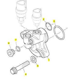
项目 零配件号码 新件号 描述
1 CH10907 1 CH10907 承接器
2 CH10875 1 CH10875 密封O型圈
3 CH10228 1 CH10228 密封O型圈
4 T400184 2 T400184 螺拴
4 CH10567 2 CH10567 螺拴
5 CH10541 2 CH10255 垫圈
6 CH10285 1 CH10285 栓塞
6 CH10282 1 CH10282 栓塞
7 T409314 1 T409314 密封O型圈
7 CH10132 1 CH10132 密封O型圈
Contents
1 General infor mation
Intr oduction . ... ... ... ... ... ... ... ... ... ... ... ... ... ... ... ... ... ... ... ... ... ... ... ... ... ... ... ... ... ... ... ... ... ... ... ... 1
Safety precautions ... ... ... ... ... ... ... ... ... ... ... ... ... ... ... ... ... ... ... ... ... ... ... ... ... ... ... ... ... ... ... ... ... 2
How to care for your engine .. ... ... ... ... ... ... ... ... ... ... ... ... ... ... ... ... ... ... ... ... ... ... ... ... ... ... ... ... 3
Engine lift equipment ... ... ... ... ... ... ... ... ... ... ... ... ... ... ... ... ... ... ... ... ... ... ... ... ... ... ... ... ... ... ... ... 3
Welding ... ... ... ... ... ... ... ... ... ... ... ... ... ... ... ... ... ... ... ... ... ... ... ... ... ... ... ... ... ... ... ... ... ... ... ... ... ... 3
Engine preservation . ... ... ... ... ... ... ... ... ... ... ... ... ... ... ... ... ... ... ... ... ... ... ... ... ... ... ... ... ... ... ... ... 3
Parts and ser vice .. ... ... ... ... ... ... ... ... ... ... ... ... ... ... ... ... ... ... ... ... ... ... ... ... ... ... ... ... ... ... ... ... ... 3
Service literature ... ... ... ... ... ... ... ... ... ... ... ... ... ... ... ... ... ... ... ... ... ... ... ... ... ... ... ... ... ... ... ... ... ... 3
Tr aining ... ... ... ... ... ... ... ... ... ... ... ... ... ... ... ... ... ... ... ... ... ... ... ... ... ... ... ... ... ... ... ... ... ... ... ... ... ... 3
POWERPART recommended consumable pr oducts . ... ... ... ... ... ... ... ... ... ... ... ... ... ... ... ... ... 4
Engine identification . ... ... ... ... ... ... ... ... ... ... ... ... ... ... ... ... ... ... ... ... ... ... ... ... ... ... ... ... ... ... ... ... 5
Engine data ... ... ... ... ... ... ... ... ... ... ... ... ... ... ... ... ... ... ... ... ... ... ... ... ... ... ... ... ... ... ... ... ... ... ... ... 6
2 Engine vi ews
Intr oduction . ... ... ... ... ... ... ... ... ... ... ... ... ... ... ... ... ... ... ... ... ... ... ... ... ... ... ... ... ... ... ... ... ... ... ... ... 7
Location of engine parts . ... ... ... ... ... ... ... ... ... ... ... ... ... ... ... ... ... ... ... ... ... ... ... ... ... ... ... ... ... ... 7
User’s Handbook, TPD1516E, issue 1.
iii
This document has been printed from SPI². Not for Resale
![]() 3 Operation instructions
3 Operation instructions
2800 Series
How to start the engine . ... ... ... ... ... ... ... ... ... ... ... ... ... ... ... ... ... ... ... ... ... ... ... ... ... ... ... ... ... ... . 9
How to start a new, an overhauled engine or an engine which has been in storage .. ... ... . 9
How to start a cold engine in cold conditions .. ... ... ... ... ... ... ... ... ... ... ... ... ... ... ... ... ... ... ... ... 10
After the engine has star ted . ... ... ... ... ... ... ... ... ... ... ... ... ... ... ... ... ... ... ... ... ... ... ... ... ... ... ... ... 10
Engine emergency stop ... ... ... ... ... ... ... ... ... ... ... ... ... ... ... ... ... ... ... ... ... ... ... ... ... ... ... ... ... ... 11
Manual stop procedure .. ... ... ... ... ... ... ... ... ... ... ... ... ... ... ... ... ... ... ... ... ... ... ... ... ... ... ... ... ... ... 11
Engine diagnostics . ... ... ... ... ... ... ... ... ... ... ... ... ... ... ... ... ... ... ... ... ... ... ... ... ... ... ... ... ... ... ... ... 12
4 Preventive maintenance
Preventive maintenance periods ... ... ... ... ... ... ... ... ... ... ... ... ... ... ... ... ... ... ... ... ... ... ... ... ... ... 15
Schedule ... ... ... ... ... ... ... ... ... ... ... ... ... ... ... ... ... ... ... ... ... ... ... ... ... ... ... ... ... ... ... ... ... ... ... ... ... 16
How to check the coolant level ... ... ... ... ... ... ... ... ... ... ... ... ... ... ... ... ... ... ... ... ... ... ... ... ... ... ... 17
How to check the air cleaner service indicator ... ... ... ... ... ... ... ... ... ... ... ... ... ... ... ... ... ... ... ... 17
How to check the lubricating oil level ... ... ... ... ... ... ... ... ... ... ... ... ... ... ... ... ... ... ... ... ... ... ... ... 18
How to drain the primary fuel filter . ... ... ... ... ... ... ... ... ... ... ... ... ... ... ... ... ... ... ... ... ... ... ... ... ... 18
Visual inspection . ... ... ... ... ... ... ... ... ... ... ... ... ... ... ... ... ... ... ... ... ... ... ... ... ... ... ... ... ... ... ... ... ... 19
Diagnostics check ... ... ... ... ... ... ... ... ... ... ... ... ... ... ... ... ... ... ... ... ... ... ... ... ... ... ... ... ... ... ... ... ... 20
How to renew the element of the primar y fuel filter .. ... ... ... ... ... ... ... ... ... ... ... ... ... ... ... ... ... 22
How to renew the element of the secondary fuel filter . ... ... ... ... ... ... ... ... ... ... ... ... ... ... ... ... 24
How to obtain an oil sample . ... ... ... ... ... ... ... ... ... ... ... ... ... ... ... ... ... ... ... ... ... ... ... ... ... ... ... ... 26
How to renew the engine lubricating oil ... ... ... ... ... ... ... ... ... ... ... ... ... ... ... ... ... ... ... ... ... ... ... 28
How to renew the element of the lubricating oil filter ... ... ... ... ... ... ... ... ... ... ... ... ... ... ... ... ... 30
How to renew the air cleaner element .. ... ... ... ... ... ... ... ... ... ... ... ... ... ... ... ... ... ... ... ... ... ... ... 31
How to check the fan drive belts . ... ... ... ... ... ... ... ... ... ... ... ... ... ... ... ... ... ... ... ... ... ... ... ... ... ... 32
How to adjust the tension of the fan belts ... ... ... ... ... ... ... ... ... ... ... ... ... ... ... ... ... ... ... ... ... ... 32
How to adjust the tension of the alternator belt .. ... ... ... ... ... ... ... ... ... ... ... ... ... ... ... ... ... ... ... 33
How to renew the fan drive belts ... ... ... ... ... ... ... ... ... ... ... ... ... ... ... ... ... ... ... ... ... ... ... ... ... ... 34
How to renew the alternator belt . ... ... ... ... ... ... ... ... ... ... ... ... ... ... ... ... ... ... ... ... ... ... ... ... ... ... 34
How to inspect the crankshaft vibration damper ... ... ... ... ... ... ... ... ... ... ... ... ... ... ... ... ... ... ... 34
Earth stud .. ... ... ... ... ... ... ... ... ... ... ... ... ... ... ... ... ... ... ... ... ... ... ... ... ... ... ... ... ... ... ... ... ... ... ... ... 35
Hoses and hose clips . ... ... ... ... ... ... ... ... ... ... ... ... ... ... ... ... ... ... ... ... ... ... ... ... ... ... ... ... ... ... ... 36
How to clean the radiator .. ... ... ... ... ... ... ... ... ... ... ... ... ... ... ... ... ... ... ... ... ... ... ... ... ... ... ... ... ... 37
How to inspect the engine mountings ... ... ... ... ... ... ... ... ... ... ... ... ... ... ... ... ... ... ... ... ... ... ... ... 37
How to drain the coolant system ... ... ... ... ... ... ... ... ... ... ... ... ... ... ... ... ... ... ... ... ... ... ... ... ... ... 38
iv
User’s Handbook, TPD1516E, is sue 1.
This document has been printed from SPI². Not for Resale
![]() 2800 Series
2800 Series
How to clean the coolant system . ... ... ... ... ... ... ... ... ... ... ... ... ... ... ... ... ... ... ... ... ... ... ... ... ... . 38
How to fill the coolant system ... ... ... ... ... ... ... ... ... ... ... ... ... ... ... ... ... ... ... ... ... ... ... ... ... ... ... . 38
How to check the tappet clearanc es ... ... ... ... ... ... ... ... ... ... ... ... ... ... ... ... ... ... ... ... ... ... ... ... . 39
How to check/adjust the electronic unit injectors ... ... ... ... ... ... ... ... ... ... ... ... ... ... ... ... ... ... . 42
Engine protection devices .. ... ... ... ... ... ... ... ... ... ... ... ... ... ... ... ... ... ... ... ... ... ... ... ... ... ... ... ... . 43
How to renew the thermostats of the coolant system ... ... ... ... ... ... ... ... ... ... ... ... ... ... ... ... . 44
How to clean and to c alibrate the engine speed/timing sensors ... ... ... ... ... ... ... ... ... ... ... . 46
How to inspect the turbochargers ... ... ... ... ... ... ... ... ... ... ... ... ... ... ... ... ... ... ... ... ... ... ... ... ... . 47
How to inspect the battery charging alternator ... ... ... ... ... ... ... ... ... ... ... ... ... ... ... ... ... ... ... . 47
How to inspect the starter m otor .. ... ... ... ... ... ... ... ... ... ... ... ... ... ... ... ... ... ... ... ... ... ... ... ... ... . 48
How to inspect the coolant pump . ... ... ... ... ... ... ... ... ... ... ... ... ... ... ... ... ... ... ... ... ... ... ... ... ... . 48
How to eliminate air from the fuel system . ... ... ... ... ... ... ... ... ... ... ... ... ... ... ... ... ... ... ... ... ... . 49
5 Engine fl uids
Fuel specification .. ... ... ... ... ... ... ... ... ... ... ... ... ... ... ... ... ... ... ... ... ... ... ... ... ... ... ... ... ... ... ... ... . 51
Coolant . ... ... ... ... ... ... ... ... ... ... ... ... ... ... ... ... ... ... ... ... ... ... ... ... ... ... ... ... ... ... ... ... ... ... ... ... ... . 51
Lubricating oil s pecification ... ... ... ... ... ... ... ... ... ... ... ... ... ... ... ... ... ... ... ... ... ... ... ... ... ... ... ... . 52
Warranty .. ... ... ... ... ... ... ... ... ... ... ... ... ... ... ... ... ... ... ... ... ... ... ... ... ... ... ... ... ... ... ... ... ... ... ... ... . 52
6 Fault diagnosis
Problems and possible causes . ... ... ... ... ... ... ... ... ... ... ... ... ... ... ... ... ... ... ... ... ... ... ... ... ... ... . 53
List of possible causes ... ... ... ... ... ... ... ... ... ... ... ... ... ... ... ... ... ... ... ... ... ... ... ... ... ... ... ... ... ... . 54
User’s Handbook, TPD1516E, issue 1.
v
This document has been printed from SPI². Not for Resale
This page is intentionally blank
This document has been printed from SPI². Not for Resale
![]()
|
General information
Introduction
1
The 2806-18 diesel engine is the latest development from Perkins Engines Company Limited, a world leader
in the design and manufacture of high performance diesel engines. More than fifty years of diesel production
experience, together with the use of the lates t technology, have been used in the manufacture of your engine
to give you reliable and economic power.
To ensure that y ou use the relevant information for your specific engine type, refer to "Engine identification"
on page 5.
The terms "left side" and "right side" apply when the engine is seen from the rear end, the flywheel end.
Number one cylinder is at the front end of the engine
Danger is indicated in the text by two methods:
Warning! This indicates that there is a possible danger to the person.
Caution: This indicates that there is a possible danger to the engine.
Note: Is used where the information is important, but there is not a danger.
User’s Handbook, TPD1516E, Issue 1
1
This document has been printed from SPI². Not for Resale
![]() 1
1
Safety precautions
2800 Series
These safety precautions are important. You must refer also to the loc al regulations in the country of use.
Some items only apply to specific applications.
Always refer to the text of this handbook for specific warnings and cautions.
Only use these engines in the type of application for which they have been designed.
Do not change the specification of the engine.
Do not make adjustments that you do not understand.
Do not allow the engine to stand on its sump.
Do not smoke when y ou put fuel in the tank.
Clean away fuel which has been spilt. Material which has been contaminated by fuel must be moved to a
safe place.
Do not put fuel in the tank while the engine runs (unles s it is absolutely necessary).
Do not clean, add lubricating oil, or adjust the engine while it runs (unless you have had the correct training;
even then extreme caution must be used to prev ent injury).
Ensure that the engine does not run in a location where it can cause a concentration of toxic emissions.
Other persons must be kept at a safe distance while the engine or auxiliary equipment is in operation.
Do not permit loose clothing or long hair near moving parts.
Warning! Keep away from moving parts during engine operation. Some moving parts cannot be seen clearly
while the engine runs.
Do not operate the engine if a safety guard has been removed.
Do not remove the filler cap or any component of the coolant system while the engine is hot and while the
coolant is under pressure, becaus e dangerous hot coolant can be discharged.
Do not allow sparks or fire near the batteries (especially when the batteries are on charge) because the
gases from the electrolyte are highly flammable. The battery fluid is dangerous to the skin and especially
to the eyes.
Disconnect the battery terminals before a repair is made to the electrical system. Always disconnect the
negative terminal first.
Only one person must control the engine.
Ensure that the engine is operated only from the control panel or from the operator's position.
If your skin comes into contact with high-pressure fuel, obtain medical assistance immediately.
Diesel fuel and lubricating oil (especially used lubricating oil) can damage the skin of certain persons.
Protect your hands with gloves or a special solution to protect the skin.
Do not wear clothing which is contaminated by lubricating oil. Do not put material which is contaminated
with oil into the pockets.
Discard used lubricating oil and coolant in accordance with local regulations to prevent contamination.
The combustible material of some components of the engine (for example certain seals) can become
extremely dangerous if it is burned. Never allow this burnt material to come into contact with the skin or with
the eyes.
Always use a safety cage to protect the operator when a c omponent is to be pressure tested in a container
of water. Fit safety wires to secure the plugs which seal the hose connections of a component which is to
be pressure tested.
Do not allow compres sed air to contact your skin. If compressed air enters your skin, obtain medical help
immediately.
Turboc hargers operate at high speed and at high temperatures. Keep fingers, tools and debris away from
the inlet and outlet ports of the turbocharger and prevent contact with hot surfaces.
Some components are not waterproof and should not be washed with a high-pressure water jet or steam.
Do not wash an engine while it runs or while it is hot. If cold cleaning fluids are applied to a hot engine,
certain components on the engine could be damaged.
Fit only genuine Perkins parts.
2
User’s Handbook, TPD1516E, Issue 1
This document has been printed from SPI². Not for Resale
![]() 2800 Series
2800 Series
How to care for your engine
1
Warning! Read the "Safety precautions" and remember them. They are given for your protection and must be
applied at all times.
Caution: Do not clean an engine while it runs. If cold cleaning fluids are applied to a hot engine, certain
components on the engine may be damaged.
To obtain the best performance and the longest life from your engine, you must ensure that the maintenance
operations are done at the correct intervals, refer to "Preventive maintenance periods" on page 15.
Ens ure that all adjustments and repairs are done by personnel who have had the correct training.
Engine lift equipment
Warning! The lifting eyes which are fitted to the engine must be used for lifting only the engine. Do not use
them to lift the engine if it is still attached to its driven unit.
Welding
Welding can cause damage to the electronic components fitted to the engine. If welding is necessary, the
precautions which follow must be undertaken before and during the welding operation.
Cautions:
Switch off the engine.
Disconnect the cable from the negative terminal of the battery. If the machine is fitted with a battery
disconnect the switch then open the switch.
If welding to the engine, remove the ECM (electronic control module).
If welding onto the machine chassis, ensure that the earth clamp is attached as close to the welding point
as possible and NOT near to the ECM.
If it is necessary to weld near to the ECM, remove the ECM from the engine.
Engine preservation
1E2566C - Lowest protection level: This process is for protection of engines for up to 30 days. The engine must
be stored inside and shipped in a closed container.
1E2566B - Intermediate protection level: This process will protect engines from functional deterioration for a
minimum of 6 months in outside storage conditions.
1E2566A - Highest protection level: This process will protect engines from functional deterioration for a
minimum of 12 months in outside storage conditions. This process is used to extend the protec tion given by
the intermediate level protection process.
Part s and service
If problems occur with your engine or with the components fitted to it, your authorised distributor can make the
necessary repairs and will ensure that only the correct parts are fitted and that the work is done correctly.
Service literature
Work shop manuals and other s ervice publications are available from your authorised distributor.
Training
Courses on the serv ice and overhaul of the 2806 engine are available at the Factory. For details apply to: The
Product Training Centre, Perkins Engines Company Limited, Peterborough, PE1 5NA, England.
User’s Handbook, TPD1516E, Issue 1 3
This document has been printed from SPI². Not for Resale
![]() 1
1
POWERPART recommended consumable products
2800 Series
|
service and maintenance of your engine and your machine. The instructions for the use of each product are
given on the outside of each container. These products are available from your Perkins distributor.
POWERPART ELC (Extended Life Coolant).
ELC is pre-mixed and protects the c ooling system against frost and corrosion. Part number 21820181.
POWERPART Easy flush
Cleans the cooling system. Part number 21825001.
POWERPART Gasket and flange sealant
To seal flat faces of components where no joint is used. Especially suitable for aluminium components.
Part number 21820518.
POWERPART Gasket remover
An aerosol for the removal of sealants and adhesives. Part number 21820116.
POWERPART Griptite
To improve the grip of worn tools and fasteners. Part number 21820129.
POWERPART Hydraulic threadseal
To retain and seal pipe connections with fine threads. Especially suitable for hydraulic and pneumatic systems.
Part number 21820121.
POWERPART Industrial grade super glue
Instant adhesive designed for metals, plas tics and rubbers . Part number 21820125.
POWERPART Lay-Up 1
A diesel fuel additive for protection against corrosion. Part number 1772204.
POWERPART Lay-Up 2
Protects the inside of the engine and of other closed systems. Part number 1762811.
POWERPART Lay-Up 3
Protects outside metal parts. Part number 1734115.
POWERPART Metal repair putty
Designed for external repair of metal and plastic. Part number 21820126.
POWERPART Pipe sealant and sealant primer
To retain and seal pipe connections with coarse threads. Pressure systems can be used immediately.
Part number 21820122.
POWERPART Radiator stop leak
For the repair of radiator leaks. Part number 21820127.
POWERPART Retainer (high strength)
To retain components which have an interference fit. Part number 21820638.
POWERPART Retainer (oil tolerant)
To retain components which have an interference fit, but are in contac t with oil. Part number 21820608.
POWERPART Safety cleaner
General cleaner in an aerosol container. Part number 21820128.
Continued
4
User’s Handbook, TPD1516E, Issue 1
This document has been printed from SPI². Not for Resale
![]() 2800 Series
2800 Series
POWERPART Silicone adhesive
1
|
|
|
sealing flange where oil resistance is needed and movement of the joint occurs. Part number 21826038.
POWERPART Silicone RTV sealing and jointing compound
Silicone rubber sealant which prevents leakage through gaps. Part number 1861108.
POWERPART Stud and bearing lock
To provide a heavy duty seal to components that have a light interference fit. Part number 21820119 or
21820120.
POWERPART Threadlock and nutlock
To retain small fasteners where easy removal is necessary. Part number 21820117 or 21820118.
POWERPART Universal jointing compound
Universal jointing compound whic h seals joints. Part number 1861117.
(1) Powerpart (ELC) is not recommended for the 1300 Series.
(2) These product are not recommended for the 4006-23 engine.
Engine identification
If you need parts, service or information for your engine, you must give the complete engine number. The
engine number is stamped on a data plate which is fastened to the right side of the engine.
A ty pical engine number is: HQD060003U2041L, which consists of these codes:
|
H |
Cod e for engine capaci ty |
|
Q |
Engine application |
|
D |
Engine type |
|
06 |
Number of engi ne cylinders |
|
0003 |
Engine specification number |
|
U |
The country of man ufacture |
|
2041 |
Build line number |
|
L |
Year of manufacture |
User’s Handbook, TPD1516E, Issue 1
5
This document has been printed from SPI². Not for Resale
![]() 1
1
Engine data
2800 Series
|
Cylinder arrangement ... ... ... ... ... ... ... ... ... ... ... ... ... ... ... ... ... ... ... ... ... ... ... ... ... ... ... ... . Vertical in line
Cycle .. ... ... ... ... ... ... ... ... ... ... ... ... ... ... ... ... ... ... ... ... ... ... ... ... ... ... ...Four stroke, compression ignition
Induction system ... ... ... ... ... ... ... ... ... ... ... ... ... ... ... ... ... ... ... ... .. Turbocharged, air to air c harge cooling
Combustion system ... ... ... ... ... ... ... ... ... ... ... ... ... ... ... ... ... ... ... ... ... ... ... ... ... ... ... ... ... Direct injection
Nominal bore.. ... ... ... ... ... ... ... ... ... ... ... ... ... ... ... ... ... ... ... ... ... ... ... ... ... ... ... ... ... ... 145 mm (5.709 in)
Nominal stroke .. ... ... ... ... ... ... ... ... ... ... ... ... ... ... ... ... ... ... ... ... ... ... ... ... ... ... ... ... ... 183 mm (7.205 in)
Compression ratio.. ... ... ... ... ... ... ... ... ... ... ... ... ... ... ... ... ... ... ... ... ... ... ... ... ... ... ... ... ... 14.5:1 Nominal
Cubic capacity ... ... ... ... ... ... ... ... ... ... ... ... ... ... ... ... ... ... ... ... ... ... ... ... ... ... ... 18,13 litres (1106.36 in )
Firing order. ... ... ... ... ... ... ... ... ... ... ... ... ... ... ... ... ... ... ... ... ... ... ... ... ... ... ... ... ... ... ... ... .. 1, 5, 3, 6, 2, 4
Direction of rotation ... ... ... ... ... ... .. Anti-clockwise viewed on flywheel (cylinder 1 furthest from the flywheel)
Total weight Electropak.. ... ... ... ... ... ... ... ... ... ... ... ... ... ... ... ... ... ... ... ... ... ... ... ... (dry) 2081 kg (4588 lb)
... ... ... ... ... ... ... ... ... ... ... ... ... ... ... ... ... ... ... ... ... ... ... ... ... ... ... ... ... ... ... ... ... ... (wet) 2190 kg (4828 lb)
Lubricating oil capacity:
Total system... ... ... ... ... ... ... ... ... ... ... ... ... ... ... ... ... ... ... ... ... ... ... ... ... ... ... ... 55,5 litres (97.7 UK pints)
Sump maximum. ... ... ... ... ... ... ... ... ... ... ... ... ... ... ... ... ... ... ... ... ... ... ... ... ... ... 53,5 litres (94.1 UK pints)
Sump minimum.. ... ... ... ... ... ... ... ... ... ... ... ... ... ... ... ... ... ... ... ... ... ... ... ... ... ... 37,5 litres (66.0 UK pints)
Lubricating oil pressure:
At rated speed ... ... ... ... ... ... ... ... ... ... ... ... ... ... ... ... ... ... ... ... ... ... ... ... ... ... ... ... ... ... ... ... ... ... . 4,2 bar
Coolant System:
Coolant capac ity of engine and radiator ... ... ... ... ... ... ... ... ... ... ... ... ... ... ... ... ... 61 litres (107.3 UK pints)
6
User’s Handbook, TPD1516E, Issue 1
This document has been printed from SPI². Not for Resale
![]()
|
Engine views
Introduction
2
Perkins engines are built for specific applications and the views which follow do not necessarily match your
engine specification.
Location of engine parts
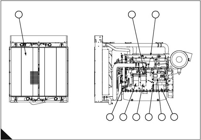
Front and left side view of engine (A)
1 Radiator 6 Earth stud
2 Hand priming pump 7 Secondary fuel filter
3 Rocker cover 8 Primar y fuel filter
4 Starter motor 9 Speed/timi ng sensor (crankshaft)
5 El ectronic Control Module (ECM)
1
2
3
9
8
7
6
5
4
A
2806/001
User’s Handbook, TPD1516E, Issue 1
7
This document has been printed from SPI². Not for Resale
![]() 2
2
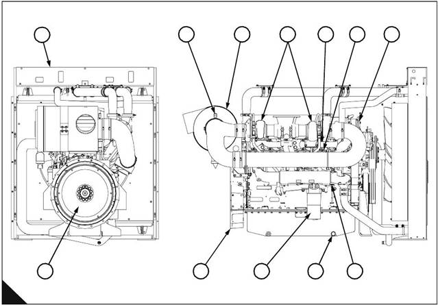
Rear and right side view of engine (B)
1 Radiato r
2 Restriction indicator
3 Air cl eaner
4 Turbochargers
5 Exhaust manifo ld
6 Filler cap for lubricating oil
7
8
9
10
11
12
Thermosta t housing
Dipstick
Sump d rai n plug
Lubr icati ng oil filte r
Flywheel housing
Flywheel
2800 Series
1
2
3
4
5
6
7
B
12
11
10
9
8
2806/002
8
User’s Handbook, TPD1516E, Issue 1
This document has been printed from SPI². Not for Resale
![]()
|
Operation instructions
How to start the engine
Before the engine is started
3
Perform the required daily maintenance and other periodic maintenance before the engine is started. Refer to
"Preventive maintenance periods" on page 15.
Check the fuel supply. Drain water from the water separator. Open the fuel supply valve.
Caution: All valves in the fuel return line must be open before and during engine operation to help prevent
high fuel pressure. High fuel pressure can cause failure of the filter housing or other damage.
Note: If the engine has not been started for several weeks, fuel may have drained from the fuel system. Air
may have entered the filter housing. Also, when fuel filters have been changed, some air pockets will be
trapped in the engine. If necessary refer to "How to eliminate air from the fuel system" on page 49.
Do not start the engine or move any of the controls if there is a “DO NOT OPERATE” label or similar
warning label attached to the start switch or to the controls.
Ensure that the areas around rotating parts are clear.
Reset all of the shutdown devices or alarm components.
Check the level of the engine lubricating oil. Maintain the oil level between the “L” and the “H” mark s on the
dipstick.
Check the level of the coolant. Maintain the level of coolant within 13 mm (0.5 inch) of the bottom of the
filler pipe. If the engine is fitted with a sight glass, maintain the coolant level in the sight glass.
Check the service indicator for the air cleaner. When the red warning indicator is seen through the clear
panel after the engine has stopped, the air filter element must be renewed.
Ensure that any driven equipment has been disengaged. Remove any electrical loads.
How to start a new, an overhauled engine or an engine which has been in storage
Prime the turbocharger. This can be achieved by operating the engine briefly with the injection disable switch
on.
When a new engine, or an engine which has been serviced, is first started, prepare to stop the engine if an
overspeed condition occurs. Use the quickest method available, for example: Emergency Stop button.
Start procedure
This start procedure may be used for all engines which are not fitted with an air inlet heater.
Refer to the Owner's Manual of the OEM for your type of controls. Use this procedure to start the engine:
1 Move the ignition switch to the ON position. If a system fault is indicated by, for example a panel light,
inves tigate the c ause. If necessary use the Perkins Electronic Service Tool, EST.
2 Push the start button or turn the ignition switch to the START position to operate the engine.
3 If the engine fails to start within 30 seconds, releas e the start button or ignition switch. Wait for 30 seconds
to allow the starter motor to cool before attempting to start the engine again.
Note: A system fault may be indicated after the engine is started. If this occurs the ECM has detected a
problem with the system. Investigate the cause, if necessary use the Perkins service tool EST.
Caution: Oil pressure should rise within 15 seconds after the engine starts. The electronic engine controls
monitor the oil pressure and will stop the engine if the oil pressure is below normal.
User’s Handbook, TPD1516E, Issue 1
9
This document has been printed from SPI². Not for Resale
![]() 3
3
2800 Series
4 If possible, allow the engine to run at no load for approximately three minutes. Run the engine at no load
until the water temperature gauge has started to rise. Check all gauges during the warm-up period.
How to start a cold engine in cold conditions
Refer to the Owner's Manual of the OEM for your type of controls. Use the procedure which follows to start the
engine.
Warning! Ether type fuels must not be used in the 2806-18 six cylinder engine.
The engine will start without aids down to a temperature of -10 °C (14 °F), but the ability to start at temperatures
below 10 °C (50 °F) will improve by the use of a cylinder block coolant heater or a device which heats the
crankcase oil. This will help to reduce white smoke and misfires when the engine is started in cold weather.
Note: If the engine has not been run for several weeks, fuel may have drained. Air may have moved into the
filter housing. Also, when fuel filters have been changed, some air will be left in the filter housing. Refer to "How
to eliminate air from the fuel system" on page 49.
1 Move the ignition switch to the ON position. If a system fault is indicated by, for example a panel light,
investigate the cause. If necessary use the Perkins Electronic Service Tool, EST.
2 Push the start button or turn the ignition s witch to the START position to crank the engine.
3 If the engine fails to start within 30 seconds, release the start button or ignition switch. Wait for 30 seconds
to allow the starter motor to cool before attempting to start the engine again. Repeat for a maximum of three
times; if the engine fails to start investigate the cause,
4 A system fault may be indicated after the engine is started. If this occurs the ECM has detected a problem
with the system. Investigate the cause, if necessary use the Perkins service tool EST. Refer to the Diagnostic
Manual for more information on engine diagnostics.
Note: Oil pressure should rise within 15 s econds after the engine starts. The electronic engine controls monitor
the oil pressure and will stop the engine if the oil pressure is below normal.
5 If possible, allow the engine to run at no load for approximately three minutes. Run the engine at no load
until the coolant temperature gauge starts to rise. Check all gauges during the warm-up period.
Caution: The oil press ures and fuel pressures should be in the normal range on the instrument panel. Do not
apply a load to the engine until the oil pressure gauge indicates at leas t normal pressure. Inspect the engine
for leaks and/or unusual noises.
Important notes
The cold start strategy will be activated when the coolant temperature is below 17 °C (63 °F). The cold start
strategy will continue until the coolant temperature reaches 28 ° C (82 °F), or until the engine has been running
for 14 minutes. A timer will disable the cold start strategy after a maximum time of 14 minutes.
If the cold start strategy is active and if the ECM measures engine speed, the engine power that is available is
reduced.
After the ECM has completed the cold mode (or the cold mode is disabled), it cannot be enabled again until
the ECM is switched OFF.
If an engine has been stopped, for example after a fault has been indicated, do not attempt to restart the engine
until it has fully stopped.
After the engine has started
1 Check all of the gauges during the warm-up period.
2 Perform another walk-around inspection. Check the engine for fluid leaks and air leak s.
Note: Gauge readings should be observed and the data should be recorded frequently while the engine runs.
A comparison of the data over time will help to determine normal readings for each gauge, it will also help to
detect abnormal conditions of operation. Signific ant changes in the readings should be investigated.
10
User’s Handbook, TPD1516E, Issue 1
This document has been printed from SPI². Not for Resale