 English
 Espaol
 Franais
 阿拉伯
阿拉伯 中文
中文 Deutsch
 Italiano
 Português
 日本
日本 韩国
韩国 български
 hrvatski
 esky
esky Dansk
Dansk Nederlands
 suomi
suomi Ελληνικ
 印度
印度 norsk
norsk Polski
 Roman
Roman русский
 Svenska
Perkins2806柴油发动机威尔逊P700E柴油发电机配件启动马达供应商,Perkins2806柴油发动机威尔逊P700E柴油发电机配件启动马达技术价格规格咨询服务,Perkins2806柴油发动机威尔逊P700E柴油发电机配件启动马达零配件供应,Perkins2806柴油发动机威尔逊P700E柴油发电机配件启动马达售后服务中心,Perkins2806柴油发动机威尔逊P700E柴油发电机配件启动马达,Perkins2806柴油发动机威尔逊P700E柴油发电机配件启动马达详细的技术参数,

产品中心
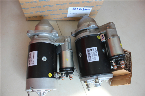
Perkins2806柴油发动机威尔逊P700E柴油发电机配件启动马达
详细描述
项目 零配件号码 新件号 描述
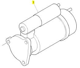
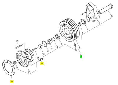
1 CH11441 1 CH11441 启动马达
项目 零配件号码 新件号 描述
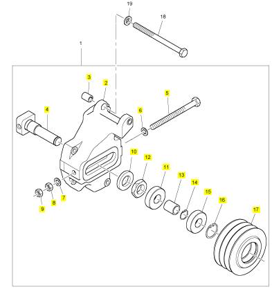
1 CH11024 1 CH11024 紧张臂
1 CH11024 1 CH11024 紧张臂
17 CH10813 4 CH10813 螺拴
18 ST15903 4 ST15903 垫圈
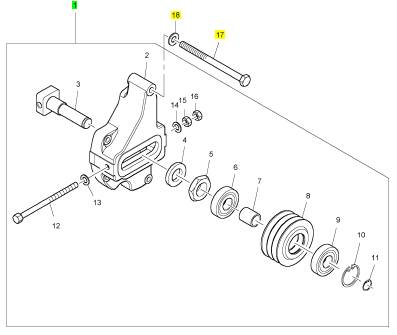
项目 零配件号码 新件号 描述
2131 A012 2 2131 A012 垫圈
2318 A210 2 2318 A210 螺帽
CH11444 2 CH11444 滚珠轴承
2 1 壳
3 CV17729 1 CV17729 轴
4 CV17731 1 CV17731 垫圈
5 CV5324 1 CV5324 螺帽
6 CH11444 1 CH11444 滚珠轴承
7 CV17765 1 CV17765 套筒
8 CV17732 1 CV17732 拉紧带轮
9 CH11444 1 CH11444 滚珠轴承
10 2722 A022 1 2722 A022 CIRCLIP
11 2721351 1 2721351 CIRCLIP
12 CV19793 1 CV19793 螺拴
13 2131 A012 1 2131 A012 垫圈
14 2131 A012 1 2131 A012 垫圈
15 2318 A210 1 2318 A210 螺帽
16 2318 A210 1 2318 A210 螺帽
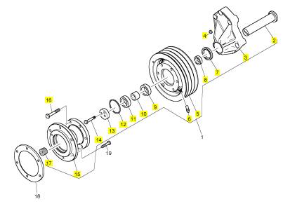
项目 零配件号码 新件号 描述
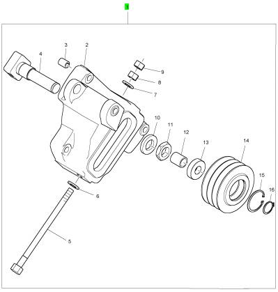
2 1 紧张
3 CH12834 1 CH12834 衬套
4 1 轴
5 1 螺拴
6 2131 A012 1 2131 A012 垫圈
7 2131 A012 1 2131 A012 垫圈
8 2318 A210 1 2318 A210 螺帽
9 2318 A210 1 2318 A210 螺帽
10 1 垫圈
11 CH11444 1 CH11444 滚珠轴承
12 1 螺帽
13 1 套筒
14 2722 A022 1 2722 A022 CIRCLIP
15 CH11444 1 CH11444 滚珠轴承
16 2721351 1 2721351 CIRCLIP
17 CH12872 1 T400228 拉紧带轮
项目 零配件号码 新件号 描述
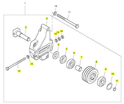
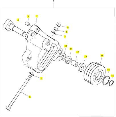
1 T400228 1 T400228 紧张臂
项目 零配件号码 新件号 描述
2 1 壳
3 CH12834 1 CH12834 衬套
4 1 轴
5 1 螺拴
6 CH11604 1 CH11604 垫圈
7 CH11604 1 CH11604 垫圈
8 T400231 1 T400231 螺帽
9 T400231 1 T400231 螺帽
10 1 垫圈
11 1 螺帽
12 1 套筒
13 CH11444 2 CH11444 滚珠轴承
14 CH12872 1 T400228 拉紧带轮
15 T400229 1 T400229 CIRCLIP
16 T400230 1 T400230 CIRCLIP
项目 零配件号码 新件号 描述
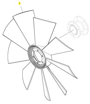
1 CH11691 1 CH11691 风扇
项目 零配件号码 新件号 描述
1 CH12385 1 CH12385 FANDRIVE
1 CH12385 1 CH12385 FANDRIVE
18 CH12433 1 CH12433 圈
19 2315 C066 6 2315 C066 螺旋
项目 零配件号码 新件号 描述
2 CH12391 1 CH12391 轴
3 1 风扇驾驶壳
4 CH12908 1 CH12908 放泄阀
4 CH12376 1 CH12908 放泄阀
5 CH12388 1 CH12388 风扇驾驶皮带轮 257.5
6 CH12374 1 CH12374 球
7 CH12378 1 CH12378 密封垫
8 CH12379 1 CH12379 间隔器
9 CH12382 1 CH12382 滚珠轴承
10 CH12383 1 CH12383 间隔器
11 CH12375 1 CH12375 滚珠轴承
12 CH12384 1 CH12384 密封O型圈
13 CH12380 1 CH12380 垫圈
14 CH12377 2 CH12377 螺拴
15 CH12390 1 CH12390 承接器
16 CH10585 6 CH10585 螺拴
17 CH10220 1 CH10220 栓塞
项目 零配件号码 新件号 描述
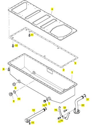
CH10132 2 CH10132 密封O型圈
CH10541 3 CH10255 垫圈
CH10815 3 CH10815 螺拴
1 CH11569 1 CH11569 油底壳
2 CH12739 1 CH12739 密封垫 -油底壳
2 CH11572 1 CH11572 密封垫 -油底壳
2 CH11904 1 CH12739 密封垫 -油底壳
3 CH12739 1 CH12739 密封垫 -油底壳
3 CH11904 1 CH12739 密封垫 -油底壳
4 CH11570 1 CH11570 板
5 CH10259 3 CH10259 栓塞
6 CH11571 1 CH11571 排泄栓塞
7 T400201 1 T400201 密封O型圈
7 CH11573 1 CH11573 密封O型圈
8 CH10748 40 CH10748 螺拴
9 CH10285 1 CH10285 栓塞
9 CH10282 1 CH10282 栓塞
10 T409314 1 T409314 密封O型圈
10 CH10665 1 CH10665 密封O型圈
11 CH10567 2 CH10567 螺拴
12 CH10567 3 CH10567 螺拴
12 CH11572 1 CH11572 密封垫 -油底壳
13 CH10786 1 CH10786 油管
14 CH11906 1 CH11906 密封O型圈
15 CH10550 2 CH10550 螺拴
16 CH10855 1 CH10855 支撑托架
17 CH10785 2 CH10785 锁紧螺母
18 CH10615 2 CH10615 垫圈
19 CH11645 1 CH11645 螺拴
20 CH11903 1 CH11903 管 - 油的吸入
21 CH11905 1 CH11905 密封O型圈
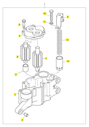
项目 零配件号码 新件号 描述
1 CH10860 1 CH10860 油泵
(1) CH10860 1 CH10860 油泵
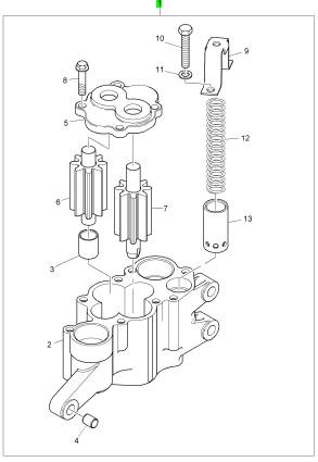
项目 零配件号码 新件号 描述
2 1 泵体
3 CH10746 2 CH10746 衬套
4 CH10747 2 CH10747 合钉
5 CH10861 1 CH10861 端盖
6 CH10862 1 CH10862 轴
7 CH10863 1 CH10863 驱动轴
8 CH10748 4 CH10748 螺拴
9 CH10736 1 CH10736 承件
10 CH10735 2 CH10735 螺拴
11 CH10541 2 CH10255 垫圈
12 CH10737 1 CH10737 弹簧
13 CH10738 1 CH10738 柱塞
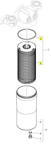
项目 零配件号码 新件号 描述
CH11139 1 CH12010 密封O型圈 U24141V
CH12010 1 CH12010 密封垫 U24142V
1 CH10929 1 CH10929 滤清器
1 CH10929 1 CH10929 滤清器
4 KRP1719 1 KRP1719 滤清器组合 U24142V
4 KRP1570 1 KRP1719 过滤器壳 U24141V
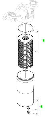
项目 零配件号码 新件号 描述
2 1 滤清器
3 CH12010 1 CH12010 密封垫
项目 零配件号码 新件号 描述
2 1 燃油滤清器
3 CH10818 1 CH10818 燃油滤清器
4 CH10316 2 CH10316 密封O型圈
5 CH10567 4 CH10567 螺拴
6 CH10541 4 CH10255 垫圈
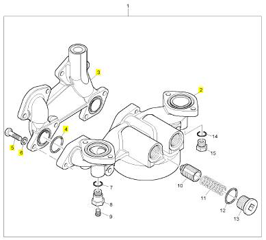
项目 零配件号码 新件号 描述
2 CH11620 2 CH11620 节温器
3 CH10766 1 CH10766 密封O型圈
4 CH10770 1 CH10770 密封垫 - 节温器壳
5 CH10056 2 CH10056 密封垫 - 节温器壳
6 CH10755 2 CH10755 密封O型圈
项目 零配件号码 新件号 描述
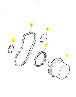
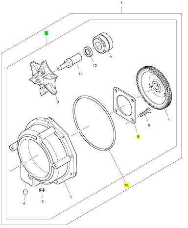
1 KRP1678 1 KRP1715 水泵装备
1 KRP1644 1 KRP1715 水泵装备
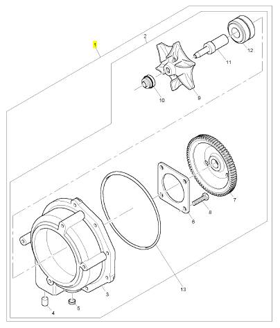
项目 零配件号码 新件号 描述
2 1 水泵
13 CH11568 1 CH11568 密封O型圈
项目 零配件号码 新件号 描述
3 1 水泵壳
4 CH11634 1 CH11634 过滤器
5 CH11545 1 CH11545 栓塞
6 CH10559 1 CH10559 保有板
7 CH11544 1 CH11544 水泵传动机构
8 CH10557 1 CH10557 螺拴
9 CH11943 1 CH11943 动叶轮
10 CH11941 1 CH12791 密封垫 - 水泵
11 CH11942 1 CH11942 轴
12 CH10558 1 CH10558 辊轴承
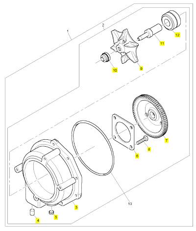
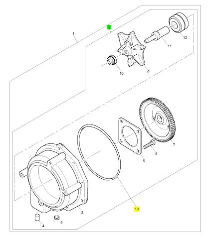
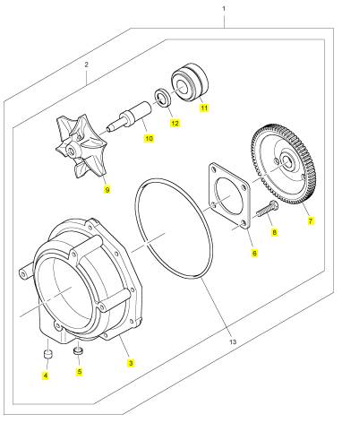
项目 零配件号码 新件号 描述
2 1 水泵
6 CH11568 1 CH11568 密封O型圈
13 CH10545 1 CH10545 密封O型圈
项目 零配件号码 新件号 描述
3 1 水泵壳
4 CH12680 1 CH12680 过滤器
5 CH11545 1 CH11545 栓塞
6 CH10559 1 CH10559 保有板
7 CH11544 1 CH11544 水泵传动机构
8 CH10557 4 CH10557 螺拴
9 CH11943 1 CH11943 动叶轮
10 CH11942 1 CH11942 轴
11 CH10558 1 CH10558 辊轴承
12 CH12791 1 CH12791 密封垫
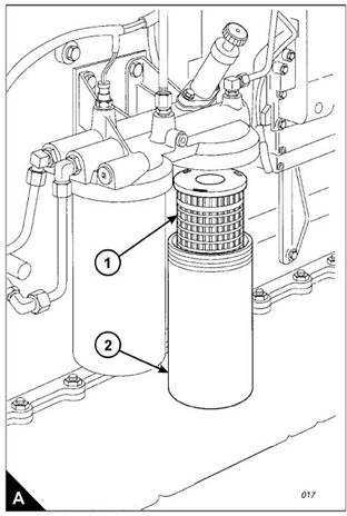
How to renew the element of the secondary fuel filter
2800 Series
Cautions:
Do not allow dirt to enter the fuel system. Clean thoroughly the area around a fuel system component that
will be disconnected. Fit a suitable cover to any disconnected component of the fuel system.
Do not loosen fuel pipes or fittings except where indicated in this user’s handbook.
1 Stop the engine.
Warning! Discard the water and fuel mixture in a safe place and in accordance with local regulations.
2 Turn the start switch to the “OFF” position. Disconnect the battery.
3 Close the fuel tank supply valve. Remove the drain plug from the base of the filter housing (A2) and drain
the fuel into a suitable container.
Warning! Discard the used filter element and ‘O’ ring seal in a safe plac e and in accordance with local
regulations.
4 Remove the filter housing, remove the ‘O’ ring seal from the housing and withdraw the filter element (A1).
5 Clean the inside of the housing and the housing thread with clean fuel oil and clean the contact face of the
filter head. Clean the drain plug and fit it to the housing.
Notes:
If a degreasing agent has been used to clean the housing, a suitable anti-seize lubricant must be applied
to the threads before the housing is fitted.
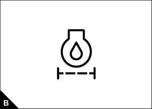
The correct filter element will be marked with the symbol shown (B).
Continued
24
User’s Handbook, TPD1516E, Issue 1
This document has been printed from SPI². Not for Resale
![]() 2800 Series
2800 Series
4
6 Fit a new element (A1) into the housing (A2). Ensure that the element engages fully with the guide in the
base of the housing. Fit a new ‘O’ ring seal to the top of the housing.
Cautions:
It is important that only genuine parts are used. The use of non Perkins parts could damage the fuel
injection equipment.
Do not fill the secondary fuel filter with fuel before installation. The fuel would not be filtered and could be
contaminated. Contaminated fuel will c ause accelerated wear to components of the fuel system.
7 Fit the housing onto the filter head. Tighten the housing to a torque of 80 Nm (59 lbf ft) 8.16 kgf m. Do not
overtighten. Ensure that the drain plug is tightened securely .
8 Clean away any fuel which has been spilled.
9 Open the fuel tank supply valve and eliminate air from the fuel system, see "How to eliminate air from the
fuel system" on page 49.
10 Check for leaks.
User’s Handbook, TPD1516E, Issue 1
25
This document has been printed from SPI². Not for Resale
![]() 4
4
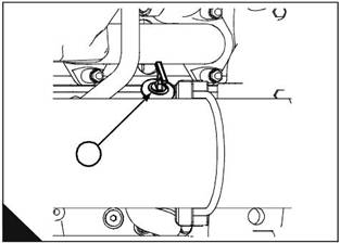
How to obtain an oil sample
2800 Series
Warning! Hot oil and hot components can cause personal injury. Do not allow hot oil or hot components to
contact the skin.
This operation must only be performed by personnel with the correct training. To avoid contamination of the
oil sample, ensure that the tools and equipment used are clean.
An oil sample kit (part number KRP1572), which includes the relevant sample bottles, is available from Perkins
dealers. Certain engines are fitted with an oil sample valve (A1), use the relevant procedure given below.
Engines fitted with an oil sample valve
1 Fit the vented cap to the sample bottle and insert the open end of the tube into the one of the holes in the cap.
Warning! Hot oil under pressure is present at the oil sample valve. Protective c lothing must be worn during
this operation. Do not allow hot oil or hot components to contact the skin.
2 With the engine running at the normal temperature of operation, remove the dust cap from the sample
valve (A1) on the engine and insert the nozzle of the tube into the sample v alve. Press the nozzle against the
valv e, the valve will open and allow the oil to flow. Ensure that the sample bottle remains upright and withdraw
the nozzle when the correct amount of oil is obtained; a mark on the bottle indicates the correct level for the
oil sample.
3 Fit the dust cap to the sample valve (A1).
4 Remove the vented cap from the sample bottle and fit the sealed cap. Dispose of the tube, nozzle and vented
cap in accordance with local regulations.
5 Complete the adhesive label and attach it to the sample bottle. Send the oil sample to a reputable oil analy sis
laboratory to provide a recommendations report.
A
1
2806/004
Continued
26
User’s Handbook, TPD1516E, Issue 1
This document has been printed from SPI². Not for Resale
![]() 2800 Series
2800 Series
Engines without an oil sample valve
4
1 Run the engine until the normal temperature of operation is achieved, stop the engine and proceed with the
operation immediately.
2 Use a vacuum pump and a long flexible tube: remove the engine oil dipstick, insert the flexible tube into the
dips tick tube and withdraw the oil sample. Fit the dipstick to the dipstick tube.
3 Complete an adhesive label and attach it to the sample bottle. Send the oil sample to a reputable oil analysis
laboratory to provide a recommendations report.
4 Ensure that all equipment used is cleaned or, if relevant, disposed of in accordance with local regulations.
User’s Handbook, TPD1516E, Issue 1
27
This document has been printed from SPI². Not for Resale
![]() 4
4
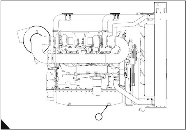
How to renew the engine lubricating oil
2800 Series
Warnings!
Hot oil and hot components can cause personal injury. Do not allow hot oil or hot components to contact
the skin.
Discard the used filter element and used engine oil in a safe place and in accordance with local regulations.
1 Operate the engine until it is warm, then stop the engine.
2 Remove the sump drain plug (A1) and drain the lubricating oil into a suitable container. Clean the drain plug
and fit a new sealing washer. Fit the drain plug and tighten it to a torque of 45 Nm (33 lbf ft) 4,6 kgf m.
3 Renew the element of the lubricating oil filter as given in "How to renew the element of the lubricating oil
filter" on page 30.
A
1
2806/005
Continued
28
User’s Handbook, TPD1516E, Issue 1
This document has been printed from SPI². Not for Resale
![]() 2800 Series
2800 Series
4
4 Clean the area around the oil filler cap (B1) and remov e the cap. Fill the sump to the “H” mark on the dipstick
(B2) with clean new lubricating oil of the correct grade as given in "Lubricating oil s pecification" on page 52.
Do NOT overfill.
To prevent damage to the crankshaft bearings, operate the engine with the fuel OFF. This will fill the oil filter
before the engine is started. Do not operate the engine c ontinuously for more than 30 seconds. Ensure that oil
pressure is indicated on the oil pressure gauge, or the service tool, before the engine is started.
5 Operate the engine at low idle speed for two minutes and check for leakage from the oil filter assembly.
6 Stop the engine and allow the oil to drain back to the sump for a minimum of ten minutes. Check the oil level
on the dipstick and, if necessary, add oil. The oil level must be between the “L” and “H” marks on the dips tick.
1
B
2806/003
User’s Handbook, TPD1516E, Issue 1
29
This document has been printed from SPI². Not for Resale
![]() 4
4
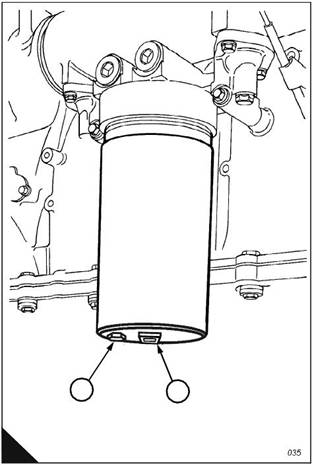
How to renew the element of the lubricating oil filter
1 Stop the engine.
2 Turn the start switch to the “OFF” position. Disconnect the battery.
2800 Series
3 Remove the drain plug (A2) from the base of the oil filter housing (A1) and drain the oil into a suitable
container.
Warning! Discard the used filter element, ‘O’ ring seal and used engine oil in a safe plac e and in accordance
with local regulations.
4 Remove the filter housing, remove the ‘O’ ring seal from the housing and withdraw the filter element.
5 Clean the housing and clean the contact face of the filter head. Clean the drain plug (A2) and fit it to the
housing.
Note: If a degreasing agent has been used to clean the housing, a suitable anti-seize lubric ant must be applied
to the threads before the housing is fitted.
Caution: It is important that only genuine Perkins parts are used. The use of non Perkins parts could damage
the engine. The correct filter element will be marked with the symbol shown (B).
6 Fit a new element into the housing, ensure that it engages fully with the guide in the base of the housing. Fit
a new ‘O’ ring s eal around the top of the housing.
7 Fit the housing onto the filter head and tighten by use of a sock et and torque wrenc h on the hexagon (A1).
Tighten the housing to a torque of 80 Nm (59 lbf ft) 8,15 kgf m. Do not overtighten. Ensure that the drain plug
is tightened securely.
8 Check the amount of engine oil in the sump. If neces sary, add oil of the correct grade and specification.
Refer to "Lubricating oil specification" on page 52.
9 Run the engine and check for leaks.
2
1
A
30
User’s Handbook, TPD1516E, Issue 1
This document has been printed from SPI². Not for Resale
![]()
![]()
![]()
![]()
![]()
![]()
![]()
![]()
![]()
![]()
![]()
![]()
![]()
![]()
![]()
![]()
![]()
![]()
![]()
![]()
![]()
![]()
![]()
![]()
![]()
![]()
![]()
![]()
![]()
![]()
![]()
![]()
![]()
![]()
![]()
![]()
![]()
![]()
![]()
![]()
![]()
![]()
![]()
![]()
![]()
![]()
![]()
![]()
![]()
![]()
![]()
![]()
![]()
![]()
![]()
![]()
![]()
![]()
![]()
![]()
![]()
![]()
![]()
![]()
![]()
![]()
![]()
![]()
![]()
![]()
![]()
![]()
![]()
![]()
![]()
![]()
![]()
![]()
![]()
![]()
![]()
![]()
![]()
![]()
![]()
![]()
![]()
![]()
![]()
![]()
![]()
![]()
![]()
![]()
![]()
![]()
![]()
![]()
![]()
![]()
![]()
![]()
![]()
![]()
![]()
![]()
![]()
![]()
![]()
![]()
![]()
![]()
![]()
![]()
![]()
![]()
![]()
![]()
![]()
![]()
![]()
![]()
![]()
![]()
![]()
![]()
![]()
![]()
![]()
![]()
![]() 2800 Series
2800 Series
How to renew the air cleaner element
The air filter contains a paper element. This must not be washed. Renew the paper element as follows:
1 Loosen the clamp and remove the end cov er (A1). Withdraw and discard the filter element (A2).
2 Clean, thoroughly, the inside of the casing (A3). Fit a new filter element and fit the end cover.
3 Reset the restriction indicator.
4
2806/006
User’s Handbook, TPD1516E, Issue 1
31
This document has been printed from SPI². Not for Resale
![]() 4
4
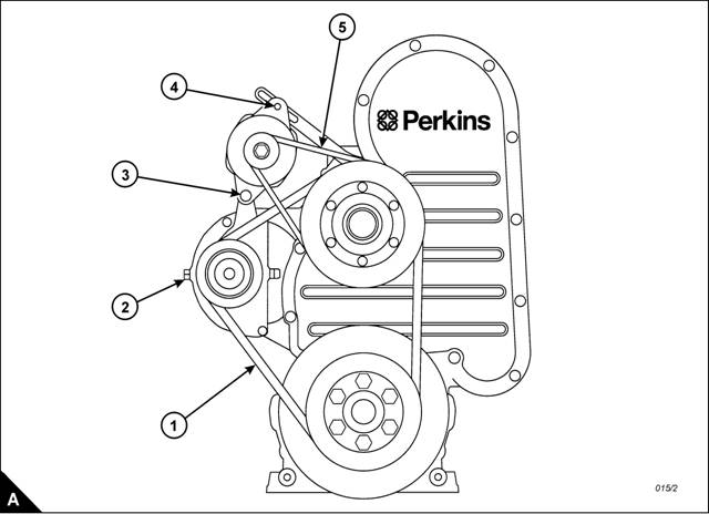
How to check the fan drive belts
2800 Series
Check all drive belts and renew a belt if it is worn or damaged. Where more than one belt is used between two
pulleys, all of the belts must be renewed together. Maximum belt life will be obtained only if the belts are kept
at the correct tensions. Where more than one belt is us ed, check/adjust the tension on the tightest belt.
How to adjust the tension of the fan belts
Remove the fan guards and proceed as follows.
Use a Borroughs belt tension gauge to check the tension at position (A1). It should be 714 N (160 lbf) 70,81
kgf. To adjust the tension, proc eed as follows:
1 Loosen the large lock nut on the belt tens ioner and turn the adjustment setscrew (A2) until the correc t tension
is obtained. Fully tighten the large lock nut to 280 Nm (207 lbf ft) 28,5 kgf m and chec k the tension of the belts
again. If the tension is correct, loosen the adjustment setscrew (A2) just enough to release the tension.
2 Fit the fan guards and run the engine for 15 minutes. With the engine stopped, remove the guards and check
again the tension.
3 When the correct tension is obtained, fit the fan guards.
32
User’s Handbook, TPD1516E, Issue 1
This document has been printed from SPI². Not for Resale
![]() 2800 Series
2800 Series
How to adjust the tension of the alternator belt
Remove the access panel in the fan guard and proceed as follows.
4
Use a Borroughs belt tension gauge to check the tension at (A5). It should be 625 N (461 lbf ft) 63,73 kgf. To
adjust the tension, proceed as follows:
1 Loosen the alternator pivot bolt (A3), the adjustment link setscrew which is behind the fan pulley and the
adjustment setscrew (A4). Move the alternator to obtain the correct belt tension and tighten the bolt/setscrews
to 70 Nm (51.63 Ibf ft) 7,14 kgf m.
2 Fit the access panel to the fan guard and run the engine for 15 minutes. Remove the access panel and check
again the tension.
3 When the correct tension is obtained, fit the access panel to the fan guard.
User’s Handbook, TPD1516E, Issue 1
33
This document has been printed from SPI². Not for Resale
![]() 4
4
How to renew the fan drive belts
1 Remove the fan guards.
2800 Series
2 Remove the six setscrews which secure the fan and hub assembly to the pulley and remove the assembly.
Caution: Take care during the removal of the fan; ensure that the radiator does not become damaged.
3 Loosen the belt tensioner and remove the old belts. Ensure that the grooves of the pulley are free from
grease and dirt and fit a new set of belts.
4 Fit the fan and tighten the setsc rews securely to 46 Nm (33.93 Ibf ft) 4,69 kgf m. Adjust the fan belts to the
correct tension, see "How to adjust the tension of the fan belts " on page 32, and fit the fan guards.
How to renew the alternator belt
1 Remove the fan guards.
2 Remove the six setscrews which secure the fan and hub assembly to the pulley and remove the assembly.
Caution: Take care during the removal of the fan; ensure that the radiator does not become damaged.
3 Loosen the adjustment bolt/setscrews to release the tension on the alternator belt and remove the old belt.
Check that the pulley grooves are clean and fit a new belt.
4 Fit the fan and tighten the setscrews securely to 46 Nm (33.93 Ibf ft) 4,69 kgf m. Adjust the alternator belt
to the correct tension, see "How to adjust the tension of the alternator belt" on page 33, and fit the fan guards.
How to inspect the crankshaft vibration damper
The viscous damper has a weight that is located inside a case filled with fluid. The weight moves in the case
to limit torsional vibration. Inspect the damper for evidence of dents, cracks or leaks of the fluid.
Renew the damper if it is dented, cracked or leaking.
The damper is mounted on the crankshaft and is located behind the belt guard at the front of the engine. Refer
to the Workshop Manual for the correct procedure to remove and to fit the damper.
34
User’s Handbook, TPD1516E, Issue 1
This document has been printed from SPI². Not for Resale
![]() 2800 Series
2800 Series
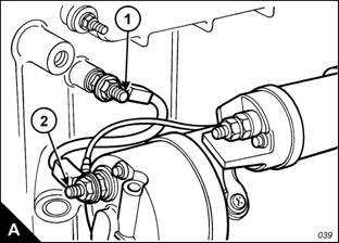
Earth stud
4
Inspect the wiring harness for good connections and inspect the condition of the harness. Check the tightness
of the earth stud (A1) at the periods specified in the service schedule. The earth stud is fitted below the ECM
at the left side of the crankcase. The earth strap is fitted between the earth stud and a terminal on the starter
motor (A2). For engines which have the starter motor fitted to the right side, or engines not fitted with an electric
starter motor, the earth strap is fitted between the earth stud and the negative terminal of the starter battery.
1 Disconnect the batteries.
2 Remove the nut which retains the earth strap on the earth stud (A1) and remove the earth strap and washer.
3 Use a suitable socket to c heck that the earth stud is torque tightened to 47 Nm (35 lbf ft) 4,8 kgf m.
Notes:
If the earth stud is remov ed, the short end must be fitted into the c rankcase.
If the earth strap is disconnected from the starter motor, it must be connected again and the nut which
retains it must be tightened to a torque of 30,5 ± 3,5 Nm (22.5 ± 2.5 lbf ft) 3,1 ± 0,3 kgf m.
4 Clean the earth stud and the earth strap with a clean cloth. If the connections are corroded, clean them with
a solution of sodium bicarbonate and water.
5 Fit the washer and the earth strap. Fit the retaining nut and tighten to a torque of 47 Nm (35 lbf ft) 4,8 kgf m.
6 Keep the earth stud and the strap clean and coated with petroleum jelly.
7 Connect the batteries.
User’s Handbook, TPD1516E, Issue 1
35
This document has been printed from SPI². Not for Resale
![]() 4
4
Hoses and hose clips
Inspect all hoses for leaks which may be caused by:
Cracks
Softness
Loose clips
Renew hoses that are crack ed or soft. Tighten any loose clips.
Check for these conditions :
End fittings that are damaged or leaking
Outer covering that is chafed or cut
Exposed wire that is used for reinforcement
Outer covering that is ballooning locally
Flexible part of the hose that is kinked or crushed
Armour that is embedded in the outer covering
To renew a hose
2800 Series
Warning! Take care during removal of the filler cap as the coolant system may be under pressure.
1 Stop the engine. Allow the engine to cool.
2 Loosen the filler cap of the coolant system slowly to relieve any pressure. Remove the filler cap.
Note: Drain the coolant into a suitable, clean container. The coolant can be used again.
3 Drain the coolant to a level below the hose which is to be renewed.
4 Remove the hose clips and remove the old hose.
5 Fit the new hose.
6 Fill the coolant system to the correct level with the specified coolant mixture.
7 Clean the filler cap and inspect the gaskets. Renew the filler cap if the gaskets are damaged. Fit the filler cap.
8 Start the engine. Inspect the coolant system for leaks.
36
User’s Handbook, TPD1516E, Issue 1
This document has been printed from SPI². Not for Resale
![]() 2800 Series
2800 Series
How to clean the radiator
4
|
exterior of the radiator, if necessary.
Warnings!
During the use of high pressure air, wear a protective face shield and protective clothing.
Maximum air pressure at the nozzle must be less than 205 kPa (30 psi) for cleaning purposes.
Use a high pressure air jet to remove loose debris. Direct the air in the opposite direction to the fan's air flow.
Hold the nozzle approximately 6 mm (0.25 in) away from the fins. Move the air nozzle slowly in a direction that
is parallel with the tubes to remove debris from between them.
A high pressure water jet may also be used to clean the radiator. The maximum water pressure for cleaning
purposes must be less than 275 kPa (40 psi) 2,8 kg/cm . Do not hold the nozzle too close to the radiator as
the fins can be damaged. Use pressurized water to soften mud. Clean the core from both sides.
Use a degreaser and steam for the removal of oil and grease. Clean both sides of the core. Wash the core with
detergent and hot water. Rinse thoroughly with clean water.
After the radiator has been c leaned, start the engine and run it at high idle speed. This will help to dry the core
and remove debris. Stop the engine and use a light bulb, held behind the core, to inspect for cleanliness. Clean
again, if necessary.
Inspect the fins for damage. Check the condition of the welds, the mounting brackets, the connections and
seals. Arrange for repairs as necessary.
How to inspect the engine mountings
Inspect the engine mountings. Check for damage or deterioration and check that the bolts are tightened to the
correct torque. Note that engine v ibration can be caused by:
Incorrect mounting of the engine.
Deterioration of the engine mounts.
If an engine mount shows signs of deterioration, it must be renewed.
User’s Handbook, TPD1516E, Issue 1
37
This document has been printed from SPI². Not for Resale
![]() 4
4
How to drain the coolant system
2800 Series
Warnings!
Do not remove the coolant filler cap while the engine is still hot and the system is under pressure because
dangerous hot coolant can be discharged.
Discard used coolant in a safe place and in accordance with local regulations.
1 Stop the engine and allow the engine to cool. Loosen slowly the filler cap of the coolant system to relieve
any pressure. Remove the filler cap.
2 Open the drain valve of the coolant system (if fitted). If the coolant system is not fitted with a drain valve,
disconnect the lowest coolant hose.
3 Allow the coolant to drain.
How to clean the coolant system
Warning! Discard used coolant in a safe place and in accordance with local regulations.
1 Drain the coolant system, see "How to drain the coolant system" on page 38.
2 Flush the coolant system with clean water.
3 Fill the coolant system, see "How to fill the coolant system" on page 38.
How to fill the coolant system
Cautions:
To av oid air locks, the coolant system must be filled at a rate not faster than 19 L (4.2 UK gal) per minute.
If the recommended coolant and procedures are not used, Perkins Engines Company Limited cannot be
held responsible for damage caused by frost or corrosion or for loss of cooling efficiency.
1 Fill the coolant system with POWERPART ELC (Extended Life Coolant), see "Coolant" on page 51. Do not
fit the filler cap.
2 Start and run the engine at idle for 1 minute to eliminate air from the cavities of the engine block. Stop the
engine.
3 Check the coolant level. Maintain the coolant level at the bottom of the filler pipe in the expansion tank.
4 Clean the filler cap of the coolant system. Inspect the gasket on the filler cap. If the gasket is damaged,
renew the filler cap. If the gasket is not damaged, use a proprietary pressure test kit to perform a test on the
filler cap. The correct pressure for the filler c ap is stamped on its face. If the filler cap does not retain the correct
pressure, fit a new filler cap.
5 Start the engine. Inspect the coolant system for leaks and for c orrect temperature of operation.
38
User’s Handbook, TPD1516E, Issue 1