 English
 Espaol
 Franais
 阿拉伯
阿拉伯 中文
中文 Deutsch
 Italiano
 Português
 日本
日本 韩国
韩国 български
 hrvatski
 esky
esky Dansk
Dansk Nederlands
 suomi
suomi Ελληνικ
 印度
印度 norsk
norsk Polski
 Roman
Roman русский
 Svenska
Perkins2806柴油发动机威尔逊P700E柴油发电机配件KRP3026活塞供应商,Perkins2806柴油发动机威尔逊P700E柴油发电机配件KRP3026活塞技术价格规格咨询服务,Perkins2806柴油发动机威尔逊P700E柴油发电机配件KRP3026活塞零配件供应,Perkins2806柴油发动机威尔逊P700E柴油发电机配件KRP3026活塞售后服务中心,Perkins2806柴油发动机威尔逊P700E柴油发电机配件KRP3026活塞,Perkins2806柴油发动机威尔逊P700E柴油发电机配件KRP3026活塞详细的技术参数,

产品中心
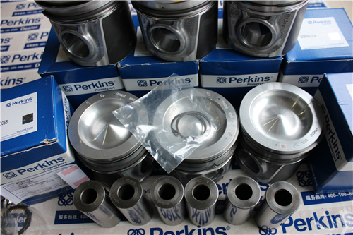
Perkins2806柴油发动机威尔逊P700E柴油发电机配件KRP3026活塞
详细描述
项目 零配件号码 新件号 描述
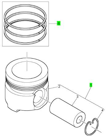
1 KRP3026 6 KRP3026 活塞装备
1 KRP3020 6 KRP3026 活塞装备 01/01/2007
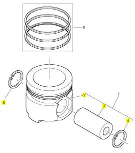
6 KRP3021 6 KRP3021 活塞环装备
项目 零配件号码 新件号 描述
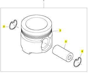
2 1 活塞
3 CH11503 1 CH11503 轴头销
4 CH11508 1 CH11508 CIRCLIP
5 CH11508 1 CH11508 CIRCLIP
项目 零配件号码 新件号 描述
2 1 活塞
3 CH11503 1 CH11503 轴头销
4 CH11992 1 CH11992 CIRCLIP
4 CH11508 1 CH11508 CIRCLIP
5 CH11992 1 CH11992 CIRCLIP
5 CH11508 1 CH11508 CIRCLIP
项目 零配件号码 新件号 描述
CH11352 1 CH11352 密封垫
1 TIMINGGEAR 盖
CH11976 14 CH10946
1 CH11848 1 CH11848 正时齿轮箱盖
1 CH11848 1 CH11848 正时齿轮箱盖
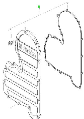
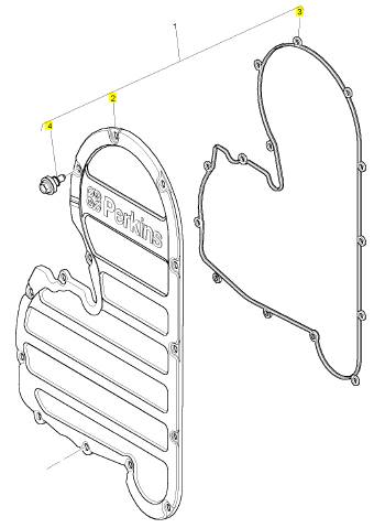
项目 零配件号码 新件号 描述
2 1 TIMINGGEAR 盖
3 CH11352 1 CH11352 密封垫
4 CH10946 14 CH10946 螺旋
4 CH11976 14 CH10946
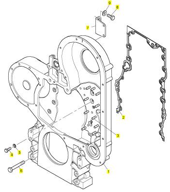
项目 零配件号码 新件号 描述
1 CH11667 1 CH11667 正时齿轮箱
1 CH11615 1 CH11667 正时齿轮箱
2 CH10829 1 CH10829 密封垫 - 正时齿轮箱
3 CH10953 10 CH10953 图钉
4 CH10815 8 CH10815 螺拴
5 CH10255 8 CH10255 垫圈
5 CH10541 8 CH10255 垫圈
6 CH10791 9 CH10791 螺拴
6 CH11476 9 CH10791 螺拴
7 CH10832 1 CH10832 支撑托架
8 CH11895 2 CH11895 螺拴
8 CH10537 2 CH11895 螺拴
9 CH10615 2 CH10615 垫圈
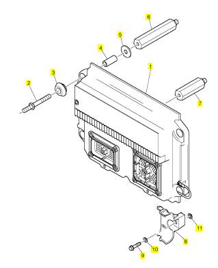
项目 零配件号码 新件号 描述
1 CH12895 1 CH12895 引擎控制组件ECM
1 CH11930 1 CH12895 引擎控制组件ECM
1 CH12104 1 CH12895 引擎控制组件ECM
2 CH10578 4 CH10578 图钉
3 CH10272 8 CH10272
4 CH10108 4 CH10108 间隔器
5 CH10279 8 CH10279 垫圈
6 CH10576 1 CH10576 架
7 CH10577 1 CH10577 架
8 CH11932 2 CH11932 托架
9 CH11931 2 CH11931 不C 螺拴
10 CH11933 2 CH11933 普通垫圈
11 CH10277 2 CH10277 垫圈
项目 零配件号码 新件号 描述
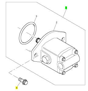
1 KRP1721 1 KRP1721 提升泵
1 KRP1679 1 KRP1721 提升泵
4 CH10582 2 CH10582 螺拴
项目 零配件号码 新件号 描述
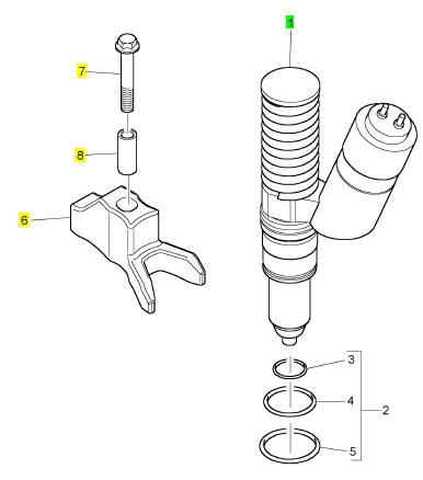
1 CH12071 6 CH12071 喷油器
1 CH12341 6 CH12071 喷油器
(1) CH12071 6 CH12071 喷油器
6 CH10790 6 CH10790 摇臂座
7 CH10791 6 CH10791 螺拴
8 CH10792 6 CH10792 间隔器
项目 零配件号码 新件号 描述
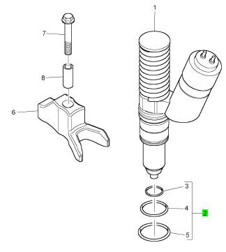
2 KRP1643 1 KRP1643 密封垫装备
项目 零配件号码 新件号 描述
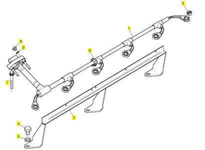
CH10970 1 CH10970 支撑托架
1 CH10974 1 CH10974 喷油器马具
2 CH10195 6 CH10195 帽
3 CH10977 1 CH10977 架设托架
4 CH10938 3 CH10938 螺拴
5 CH10099 3 CH10099 垫圈
6 CH10827 5 CH10827 缆拉杆
7 T400187 12 T400187 螺拴
7 CH10566 12 CH10566 螺拴
8 T400186 2 T400186 螺拴
8 CH10160 2 CH10160 螺拴
9 CH10303 2 CH10303 垫圈
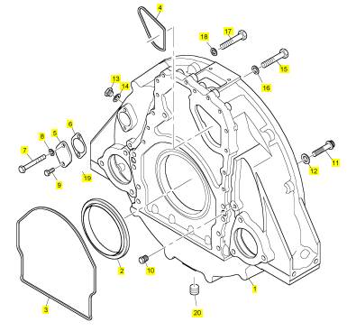
项目 零配件号码 新件号 描述
1 CH12371 1 CH12371 飞轮壳
1 CH11584 1 CH12371 飞轮壳
2 CH11304 1 CH11304 密封垫 -后油封
3 CH12062 1 CH12062 密封垫
3 CH11583 1 CH12062 密封垫
4 CH12063 1 CH12063 密封垫
4 CH11582 1 CH12063 密封垫
5 CH10539 1 CH10539 堵塞盖
6 CH10540 1 CH10540 密封垫
7 CH10538 1 CH10538 螺拴
8 CH10255 2 CH10255 垫圈
8 CH10541 2 CH10255 垫圈
9 CH11895 1 CH11895 螺拴
9 CH10537 1 CH11895 螺拴
10 CH10262 2 CH10262 栓塞
11 CH11587 9 CH11587 螺拴
12 CH10099 9 CH10099 垫圈
13 CH10939 1 CH10939 排泄栓塞
14 CH10940 1 CH10940 密封垫
15 CH11585 8 CH11585 螺拴
16 CH10255 8 CH10255 垫圈
16 CH10541 8 CH10255 垫圈
17 CH11586 7 CH11586 螺拴
18 CH10255 7 CH10255 垫圈
18 CH10541 7 CH10255 垫圈
19 CH11588 1 CH11588 栓塞
20 CH10220 1 CH10220 栓塞

![]() 2800 Series
2800 Series
How to check the tappet clearances
4
Special tools
Descript ion
Engine turning tool
Tappet clearances
Part number
CH11148
Inlet
Exhaust
0,38 +/- 0,08 mm (0.015 +/- 0.003 in)
0,76 +/- 0,08 mm (0.030 +/- 0.003 in)
|
|
operation must be done with the engine cold and stopped. Refer also to "How to check/adjust the electronic
unit injectors" on page 42.
1 Remove the rocker cover.
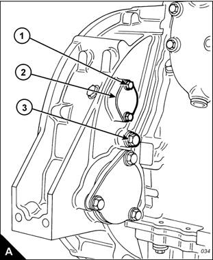
2 Remove the top bolt (A1) from the cover (A2) on the flywheel housing and slacken the other cover bolt to
allow the cover to open. The top bolt (A1) is the timing bolt.
Caution: If a customer-fitted speed sensor is fitted to the flywheel housing, it must be remov ed before the
engine turning tool c an be inserted.
3 Remove the plug (A3) from the timing bolt location in the flywheel housing and fit the timing bolt.
Note: There are two locations for the timing bolt, one at each side of the flywheel housing. Use the location
which is the most convenient.
4 Insert the engine turning tool, CH11148, into the flywheel housing through the aperture behind the cover
rotation (anti-clockwise when viewed on the flywheel) until the timing bolt engages with the threaded hole in
the flywheel. The piston of number 1 cylinder is now at TDC (top dead centre).
Caution: If the flywheel is turned past the threaded hole, the flywheel must be turned in the opposite direction
for approximately 45 degrees and then back in the normal direction of rotation until the timing bolt engages
with the threaded hole. This is to eliminate backlash.
User’s Handbook, TPD1516E, Issue 1
39
This document has been printed from SPI². Not for Resale
![]() 4
4
2800 Series
5 Check the inlet and exhaust valves of the number 1 cylinder. If they are fully closed the piston is on its
compression stroke and the rocker levers can be moved by hand. If the rocker levers can not be moved
because the valves are slightly open, the piston is on its exhaust stroke. If it is on its exhaust stroke, withdraw
the timing bolt and turn the flywheel a further 360 degrees in the normal direction of rotation so that the number
1 cylinder is set to TDC on its compression stroke, then insert again the timing bolt.
6 Before each set of tappet clearances is adjusted, ensure that the roller of the rocker lever is fully against the
camshaft lobe.
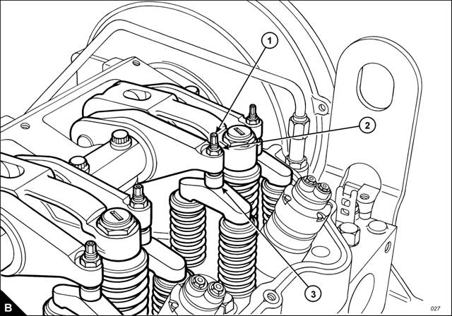
7 Use a set of feeler gauges, inserted at the position shown (B3) between the valve bridge piece and the rocker
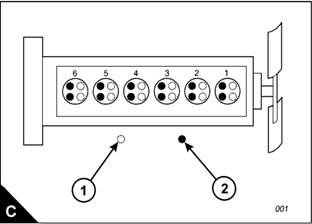
lever button, to check the tappet clearances for the inlet valves (C1) on cylinders 1, 2 and 4. Adjust the
clearances if necessary. Check the tappet clearance for the exhaust valves (C2) on cylinders 1, 3 and 5, and
adjust the clearances if neces sary.
Notes:
Move each valve bridge piece before the feeler gauge is inserted to reduce the effect of the oil film.
During the procedure, ensure that the feeler gauge is fully inserted
8 After each unit has been adjusted, tighten the lock nut (B2) of the adjustment screw (B1) to a torque of
30 ± 4 Nm (22 ± 3 lbf ft) 3 ± 0,4 kgf m.
9 Withdraw the timing bolt and rotate the flywheel by 360 degrees so that the number 6 piston is at TDC on
its compression strok e. Insert again the timing bolt into the threaded hole.
Continued
40
User’s Handbook, TPD1516E, Issue 1
This document has been printed from SPI². Not for Resale
![]() 2800 Series
2800 Series
10 Check the tappet clearances for the inlet valves (C1) on cylinders 3, 5 and 6. Adjust the clearances if
4
necessary. Check the tappet clearances for the exhaust valves (C2) on cylinders 2, 4 and 6, and adjust the
clearances if necessary.
11 After each unit has been adjusted, tighten the lock nut of the adjustment screw to a torque of 30 ± 4 Nm
(22 ± 3 lbf ft) 3 ± 0,4 kgf m.
12 Check again the tappet clearances for all six cylinders.
13 Fit the rock er cover. Remove the engine turning tool and the timing bolt and fit the cov er to the flywheel
housing.
14 Fit the plug to the timing bolt location.
User’s Handbook, TPD1516E, Issue 1
41
This document has been printed from SPI². Not for Resale
![]() 4
4
How to check/adjust the electronic unit injectors
2800 Series
|
Spec ial tools | |
|
De scription |
Part number |
|
Fuel injector setting gauge |
CH11149 |
This operation should be performed at the same time as the operation to c heck the valve tappet clearances.
Warning! The electrical circuit for the fuel injector units operates on 110 volts. Do NOT work on the fuel injector
units unless the power supply to the ECM has been disconnected.
1 With the rocker covers removed, set the number 1 piston to TDC (top dead centre) on its compression
stroke. Check/adjus t the height dimensions for the fuel injectors of cylinders 3, 5 and 6.
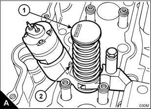
2 Use the fuel injector setting gauge, CH11149, to obtain the correct height for the fuel injector. The dimension
to be measured is from the top of the unit injector (A1) to the machined ledge on the fuel injector body (A2).
This dimension should be 78,0 ± 0,2 mm (3.07 ± 0.01 in). Slacken the lock nut and use the adjustment screw
of the rock er lever to obtain the correct dimension. Tighten the lock nut to a torque of
55 ± 10 Nm (41 ± 7 lbf ft) 5,6 ± 1 kgf m.
3 Remove the timing bolt from the flywheel housing and rotate the flywheel by 360 degrees in the normal
direction of engine rotation until the timing bolt can be inserted into the threaded hole. This will put the number
1 piston at TDC in its exhaust stroke.
4 Check/adjust the height dimensions for the fuel injectors of cylinders 1, 2 and 4 as given in step 2.
5 When all adjustments have been made, remove the timing bolt, fit the cover to the flywheel housing, fit the
plug to the timing bolt position and fit the rocker cov ers.
42
User’s Handbook, TPD1516E, Issue 1
This document has been printed from SPI². Not for Resale
![]() 2800 Series
2800 Series
Engine protection devices
4
The engine is fitted with an electronic management unit which monitors all c ritical engine temperatures and
pressures and will stop the engine if a critical fault occurs .
If any of the sensors fail, the diagnostic s indicator will be activated and your Perkins dealer should be contacted
so that the fault can be identified by use of the Perkins Electronic Service Tool (EST).
Visual inspection
Chec k visually the condition of all gauges, sensors and wiring. Look for wiring and components that are loose,
broken, or damaged. Damaged wiring or components should be repaired or renewed immediately.
User’s Handbook, TPD1516E, Issue 1
43
This document has been printed from SPI². Not for Resale

![]() 4
4
How to renew the thermostats of the coolant system
2800 Series
Renew the coolant thermostats at the periods given in the service schedule. This is recommended preventive
maintenance practice.
Warnings!
Do not remove the coolant filler cap while the engine is still hot and the system is under pressure because
dangerous hot coolant can be discharged.
Discard used coolant in a safe place and in accordance with local regulations.
Cautions:
Failure to replace the thermostats at the periods given in the service schedule c ould cause severe engine
damage.
The engine must be operated with the thermostats installed. If a thermostat is fitted incorrectly the engine
may overheat.
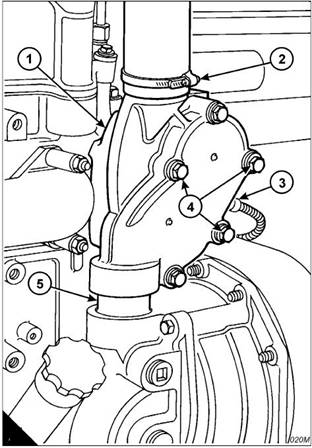
1 Drain the coolant until the level is below the thermostat housing (A1).
Caution: Certain sensors fitted to the engine have a short lead which is part of the sensor unit. For this type
of sensor ensure that the wiring harness is disconnected from the end of the lead. Do not attempt to remove
the lead from the s ensor unit.
2 Disconnec t the cable (A3) from the coolant temperature sensor.
3 Release the hose clips (A2) and disconnect the pipe and hose clip from the top of the unit.
4 Slacken the five setscrews of the thermostat housing; then remove fully the three setscrews (A4) which
retain the thermostat housing on the cy linder head.
5 Lift carefully the assembly to separate it from the coolant bobbin (A5) at its base.
44
User’s Handbook, TPD1516E, Issue 1
This document has been printed from SPI². Not for Resale
![]() 2800 Series
2800 Series
4
6 Remove the two short setscrews which remain, separate the two halves of the assembly and remove the
thermostats.
7 Clean thoroughly both parts of the assembly and check the condition of the lip-type seals. Renew the seals
if they are worn or damaged.
8 Fit the new thermostats. Ensure that the new thermostats are fitted correc tly. Fit a new ‘O’ ring type seal to
the groove in the thermos tat housing (B1), assemble the two halves of the unit and retain with the two short
setsc rews.
9 Ensure that the mating face on the cylinder head is clean.
10 Fit new seals to the coolant bobbin (B5) whic h fits into the base of the unit and lubricate the seals with a
small amount of rubber lubricant.
11 Fit a new ‘O’ ring type seal to the groove in the mating face of the housing and fit the assembly over the
coolant bobbin.
12 Fit the three setscrews (B4) which retain the thermostat housing on the cylinder head.
13 Gradually and evenly tighten the five setscrews to a torque of 38 Nm (28.0 lbf ft) 3,8 kgf m.
14 Connect the hose to the top of the housing and tighten the hose clip (B2).
15 Connect the cable (B3) to the coolant temperature sensor.
16 Fill the coolant system, s ee "How to fill the coolant system" on page 38.
B
User’s Handbook, TPD1516E, Issue 1
45
This document has been printed from SPI². Not for Resale
![]() 4
4
How to clean and to calibrate the engine speed/timing sensors
2800 Series
1 Disconnect the wiring harness from the sensor and remove the two speed-timing s ensors from the left side
of the engine at the back of the gear case.
2 Check the c ondition of the plas tic end of the sensors for wear and/or contaminants.
3 Clean the metal shavings and other debris from the face of the sensors.
4 Fit the s ensors to the correct locations and connect the wiring harness.
Note: If a new ECM unit has been fitted, or the engine gear train has been renewed or dismantled and
assembled, the engine speed/timing s ensors must be calibrated. Refer to engine timing calibration in the
Diagnostic Manual.
46
User’s Handbook, TPD1516E, Issue 1
This document has been printed from SPI². Not for Resale
![]() 2800 Series
2800 Series
How to inspect the turbochargers
4
At the periods given in the s ervice schedule, with the engine switched off and cool, disconnect and remove the
pipes from between the air filter and the turbochargers. Turn, rapidly, the rotor assembly of each turbocharger,
check for freedom of movement and for sounds of interference. If necessary, contact your Perkins
dealer/distributor.
Caution: Failure of the turbocharger bearings can cause large amounts of oil to enter the air inlet and exhaust
systems. Loss of engine lubricant can cause serious engine damage.
Minor leakage of a turbocharger housing under extended low load operation should not cause problems unless
turbocharger bearing failure has occurred.
Caution: When a turbocharger bearing failure is accompanied by a significant loss in engine performance
(exhaust smoke or engine speed up at no load), do not continue to operate the engine until the turbocharger
has been repaired or renewed.
Deposits must not be removed from the turbine wheels nor the compressor wheels or the balance of the
assembly will be adversely affected.
Chec k the oil supply and drain pipes for oil leaks.
Chec k for air leakage when the engine is run.
To remove and to fit a turbocharger
Refer the Workshop Manual for details of how to remove and to fit the turbocharger.
How to inspect the battery charging alternator
Inspect the battery charging alternator, for loose connections. Ins pect the ammeter (if fitted) during engine
operation to ensure correct battery performance and/or correct performance of the electrical system. Clean the
outside of the alternator and ens ure that the ventilation holes are c lear.
The alternator must be checked and corrected, if necessary, by a person who has had the correct training, at
the periods given in the servic e schedule.
User’s Handbook, TPD1516E, Issue 1
47
This document has been printed from SPI². Not for Resale
![]() 4
4
How to inspect the starter motor
2800 Series
Check the electrical connections of the starter motor assembly and clean them. Check the starter motor for
correc t operation.
The starter motor must be checked and corrected, if necessary, by a person who has had the correct training,
at the periods given in the service schedule.
How to inspect the coolant pump
Inspect the coolant pump for leaks. If leakage is observed, renew the coolant pump seal or the coolant pump
assembly. Refer to the Workshop Manual for the dismantle and ass embly procedures.
Refer to the Workshop Manual or consult your Perkins dealer/distributor if any repair or replacement is needed.
Notes:
A small amount of leakage of coolant across the surface of the face seal in the water pump is normal. Its
purpose is to provide lubrication for the seal.
There is a hole in the water pump body to allow coolant to drain. Small amounts of coolant might be seen
to leak intermittently from the drain hole during the engine operation cycle.
Signs of a small leakage through the drain hole are not an indication that the pump is faulty. Coolant stains
or intermittent drops of coolant from the hole, indicate normal operation of the pump.
48
User’s Handbook, TPD1516E, Issue 1
This document has been printed from SPI². Not for Resale
![]() 2800 Series
2800 Series
How to eliminate air from the fuel system
This procedure is used normally when the engine runs out of fuel.
4
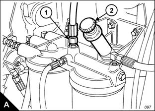
1 Loosen the union of the fuel return pipe (A1). Unlock and operate the hand priming pump (A2) until fuel, free
from air, flows from the union; this procedure will require many strokes of the pump. Use a cloth or a container
to collect the excess fuel.
2 Tighten the union (A1). Operate the hand priming pump until a strong pressure is felt on the pump. Push the
priming pump plunger inward. Tighten the plunger by hand and continue immediately with the next stage.
3 Start the engine.
Caution: Do not operate the engine c ontinuously for more than 30 seconds. Allow the starter motor to cool for
two minutes before the engine is operated again.
4 If the engine will not start, allow the starter motor to cool for 2 minutes. Repeat steps 1 and 2 to start the
engine. Continue to eliminate air from the fuel system if:
The engine starts, but runs unevenly.
The engine starts, but continues to misfire or smoke.
5 Run the engine with no load until it runs smoothly.
User’s Handbook, TPD1516E, Issue 1
49
This document has been printed from SPI². Not for Resale