 English
 Espaol
 Franais
 阿拉伯
阿拉伯 中文
中文 Deutsch
 Italiano
 Português
 日本
日本 韩国
韩国 български
 hrvatski
 esky
esky Dansk
Dansk Nederlands
 suomi
suomi Ελληνικ
 印度
印度 norsk
norsk Polski
 Roman
Roman русский
 Svenska
Perkins2506柴油发动机威尔逊P500E柴油发电机配件CH12895引擎控制组件ECM供应商,Perkins2506柴油发动机威尔逊P500E柴油发电机配件CH12895引擎控制组件ECM技术价格规格咨询服务,Perkins2506柴油发动机威尔逊P500E柴油发电机配件CH12895引擎控制组件ECM零配件供应,Perkins2506柴油发动机威尔逊P500E柴油发电机配件CH12895引擎控制组件ECM售后服务中心,Perkins2506柴油发动机威尔逊P500E柴油发电机配件CH12895引擎控制组件ECM,Perkins2506柴油发动机威尔逊P500E柴油发电机配件CH12895引擎控制组件ECM详细的技术参数,

产品中心
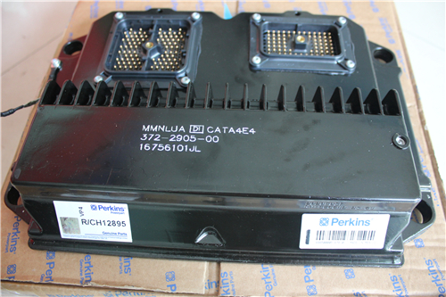
Perkins2506柴油发动机威尔逊P500E柴油发电机配件CH12895引擎控制组件ECM
详细描述
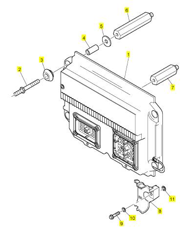
项目 零配件号码 新件号 描述
1 CH12895 1 CH12895 引擎控制组件ECM
1 CH11930 1 CH12895 引擎控制组件ECM
1 CH12104 1 CH12895 引擎控制组件ECM
2 CH10578 4 CH10578 图钉
3 CH10272 8 CH10272
4 CH10108 4 CH10108 间隔器
5 CH10279 8 CH10279 垫圈
6 CH10576 1 CH10576 架
7 CH10577 1 CH10577 架
8 CH11932 2 CH11932 托架
9 CH11931 2 CH11931 不C 螺拴
10 CH11933 2 CH11933 普通垫圈
11 CH10277 2 CH10277 垫圈
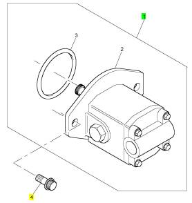
项目 零配件号码 新件号 描述
1 KRP1721 1 KRP1721 提升泵
1 KRP1679 1 KRP1721 提升泵
4 CH10582 2 CH10582 螺拴
Table
of
Contents
Charging System - Test ........................................ 54
Electric Starting System - Test .............................. 55
Index Section
Systems Operation Section
General Information ................................................ 4
Electronic Control System Components ................. 6
Fuel System ........................................................... 8
Air Inlet and Exhaust System ............................... 12
Lubrication System .............................................. 14
Cooling System .................................................... 16
Basic Engine ......................................................... 17
Electrical System ................................................. 18
Testing and Adjusting Section
Testing and Adjusting
Belt Tension Chart ................................................ 22
Fuel System
Fuel System - Inspect ........................................... 23
Air in Fuel - Test .................................................... 23
Electronic Unit Injector - Adjust ............................. 24
Electronic Unit Injector - Test ................................ 24
Finding Top Center Position for No. 1 Piston ........ 25
Fuel Quality - Test ................................................. 26
Fuel System - Prime ............................................. 26
Fuel System Pressure - Test ................................. 27
Gear Group (Front) - Time .................................... 28
Air Inlet and Exhaust System
Air Inlet and Exhaust System - Inspect ................. 31
Turbocharger - Inspect .......................................... 32
Exhaust Temperature - Test .................................. 34
Engine Crankcas e Pressure (Blowby) - Test ........ 35
Engine Valve Lash - Inspect/Adjust ...................... 35
Lubrication System
Engine Oil Pressure - Test .................................... 37
Excessive Bearing Wear - Inspect ........................ 39
Excessive Engine Oil Consumption - Inspect ....... 39
Increased Engine Oil Temperature - Inspect ........ 40
Cooling System
Cooling System - Check (Overheating) ................ 41
Cooling System - Inspect ...................................... 42
Cooling System - Test ........................................... 43
Water Temperature Regulator - Test ..................... 45
Water Pump - Test ................................................ 46
Basic Engine
Piston Ring Groove - Inspect ................................ 47
Connecting Rod Bearings - Inspect ...................... 47
Main Bearings - Inspect ........................................ 47
Cylinder Block - Inspect ........................................ 47
Cylinder Liner Projection - Inspect ........................ 48
Flywheel - Inspect ................................................. 50
Flywheel Housing - Inspect ................................... 51
Vibration Damper - Check .................................... 53
Electrical System
Battery - Test ......................................................... 54
Index ..................................................................... 56
This document has been printed from SPI². Not for Resale
![]() 4
4
Systems Operation Section
KENR6231
Systems
Operat ion
Section
General Information
i02550114
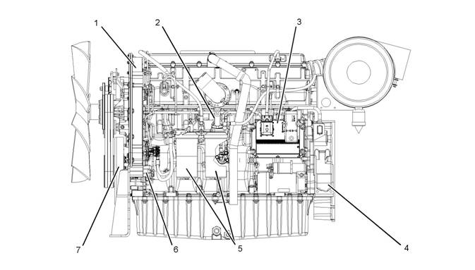
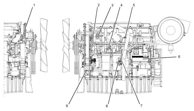
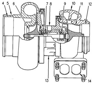
The following model views show the 2506 Engine
features. Due to individual applications, your engine
may appear different from the illustrations.
Illustration 1
Typical example
Left side view
(1) Front timing gear housing
(2) Fuel priming pump
(3) Electronic Control Module (ECM)
(4) Flywheel housing
(5) Fuel filters
(6) Fuel transfer pump
(7) Vibration Damper
g01288248
This document has been printed from SPI². Not for Resale
![]()
![]() KENR6231
KENR6231
Sy stems
5
Operation Section
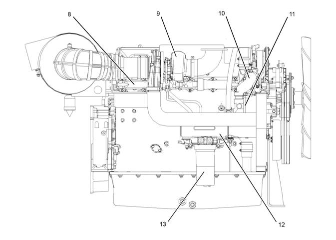
Illustration 2
Typical example
Right side view
(8) Exhaust manifold
(9) Turbocharger
(10) Temperature regulator housing
(11) Water pump
(12) Oil cooler
(13) Oil filter
g01288247
Starting the Engine
The Electronic Control Module (ECM) will
automatically provide the correct amount of fuel that
is necessary to start the engine. If the engine fails
to start in 30 seconds, the starter s witch should be
released. The starting motor should be allowed to
cool for 30 seconds before being used again.
Cold Mode Operation
The ECM will set the cold start strategy when the
coolant temperature is below 18 °C (64 °F).
Cold mode operation will be deactivated when any of
the following conditions have been met:
• Coolant temperature reaches 18 °C (64 °F).
• The engine has been running for fourteen minutes.
Cold mode operation varies the fuel injection amount
for white smoke cleanup. Cold mode operation also
varies the timing for white smoke cleanup. The
engine operating temperature is usually reached
before the walk-around inspec tion is completed.
This document has been printed from SPI². Not for Resale
![]() 6
6
Systems Operation Section
KENR6231
Electronic
Control
i02589727
System
Components
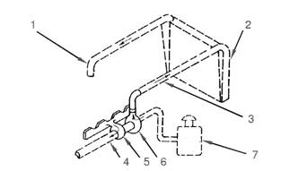
Illustration 3
(1) Coolant temperature sensor
(2) Camshaft position sensor
(3) Inlet manifold pressure sensor
(4) Fuel temperature sensor
(5) Inlet manifold temperature sensor
(6) Electronic control module (ECM)
(7) Engine oil pressure sensor
(8) Atmospheric pressure sensor
(9) Crankshaft position sensor
g01279775
The electronic control system is integrally designed
into the engine’s fuel system and the engine’s air
inlet and exhaust system in order to electronically
control the fuel delivery and the injection timing. The
•
•
Controls
Outputs
electronic control system provides increased timing
control and fuel air ratio control in comparison to
conventional mechanical engines. Injection timing
is achieved by prec ise control of injector firing time,
and engine rpm is controlled by adjus ting the firing
duration. The Electronic Control Module (ECM)
energizes the solenoid in the unit injector in order to
start the injection of fuel. Also, the ECM de-energizes
the unit injector solenoids in order to stop injection
of fuel. Refer to Systems Operation, Testing and
Adjusting, “Fuel System” for a c omplete explanation
of the fuel injec tion process.
The engine uses the following types of electronic
components:
• Inputs
An input component is one that sends an electrical
signal to the ECM. The signal that is sent varies in
one of the following ways:
• Voltage
• Frequency
• Pulse width
The variation of the signal is in response to a change
in some specific system of the vehicle. The ECM
sees the input sensor signal as information about the
condition, environment, or operation of the vehicle.
This document has been printed from SPI². Not for Resale
![]() KENR6231
KENR6231
Sy stems
7
Operation Section
A c ontrol component (ECM) receives the input
signals. Electronic circuits inside the control
component evaluate the signals from the input
components. These electronic circuits also supply
electrical energy to the output components of the
system. The electrical energy that is supplied to
the output components is based on predetermined
combinations of input signal values.
An output component is one that is operated by a
control module. The output component receives
electrical energy from the control component. The
output component uses that electrical energy in one
of two ways. The output component can use that
electrical energy in order to perform work. The output
component can use that electrical energy in order to
provide information.
This document has been printed from SPI². Not for Resale
![]()
![]() 8
8
Systems Operation Section
KENR6231
Fuel System
i02550058
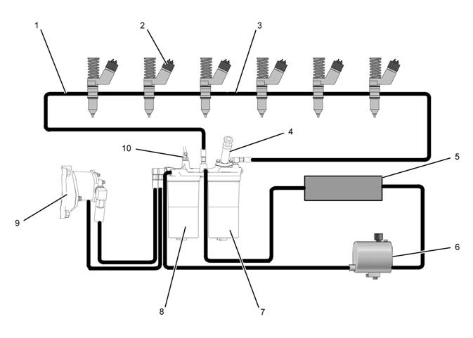
Illustration 4
Fuel system schematic
(1) Fuel return line
(2) Electronic unit injectors
(3) Fuel gallery
(4) Fuel priming pump
(5) Fuel cooler
(6) Fuel tank
(7) Secondary fuel filter
(8) Primary fuel filter
(9) Fuel transfer pump
(10) Fuel temperature sensor
g01282152
The fuel supply circuit is a conventional design for
engines with electronic unit injection. A fuel tank (6)
is used to store the fuel prior to use by the engine. A
primary fuel filter/water separator (8) is placed into
the fuel supply circuit in order to remove large debris
from the fuel. This debris may have entered the
fuel tank during fueling. The debris may have also
entered the fuel tank through the vent for the fuel
tank. The primary filter element also separates water
from the fuel. The water is collected in the bowl at the
bottom of the primary fuel filter/water separator.
Note: The inlet fuel temperature to the fuel transfer
pump must not exceed 79 °C (175 °F) when the
engine has reached normal operating temperature.
Fuel temperatures above 79 °C (175 °F) will reduce
the life of the fuel transfer pump chec k valves. The
fuel efficiency and the engine power output are
reduced when the fuel temperature increases from
30 °C (86 °F) to 70 °C (158 °F).
This document has been printed from SPI². Not for Resale
![]()
![]() KENR6231
KENR6231
Sy stems
9
Operation Section
Fuel from the tank (6) flows to the fuel filter base.
The fuel filter base contains the primary fuel filter
and the secondary fuel filter. The fuel flows through
cored passages in the fuel filter base. The fuel
priming pump (4) is mounted on the fuel filter base.
The fuel priming pump is used in order to manually
pump the fuel into the fuel system after the system,
or parts of the system have been drained. The fuel
priming pump is used in order to refill the fuel system
after air has been introduced into the system. For
more information on priming the fuel system, refer
to Systems Operation, Testing and Adjusting, “Fuel
System - Prime”.
As the fuel flows through cored passages in the fuel
filter bas e, the fuel is directed into the primary fuel
filter (8). Fuel flows out of the fuel filter and returns
to the passages in the fuel filter base. Prior to exiting
the fuel filter base, the fuel temperature is sampled
by the fuel temperature sensor (10). The signals
that are generated by the sensors are used by the
engine control in order to monitor the condition of the
engine’s components.
The fuel flows from the fuel filter base to the fuel
transfer pump (9). The fuel transfer pump (9) is a gear
type pump with fixed clearances. The fuel transfer
pump (9) incorporates an internal relief valve that
protects the fuel system from extreme pressure. In
the case of extreme pressure, fuel is redirected back
to the inlet of the fuel transfer pump (9). An outlet
check valve is used in order to prevent pressurized
fuel leakage back through the pump. The fuel transfer
pump (9) is located in the front of the engine. The fuel
transfer pump (9) is driven by the front gear train.
The fuel flows from the fuel transfer pump (9) to the
secondary fuel filter (7). The fuel is filtered in order
to remove small abrasive particles that will cause
premature wear to fuel system components. The fuel
flows from the secondary fuel filter (7) to the fuel filter
base.
The fuel is then directed from the fuel filter base
through the fuel return line (1) to fuel manifold (3) that
runs the length of the cylinder head. A continuous
flow of fuel is supplied to the electronic unit injectors
(2) in order to perform the following tasks:
• Supply fuel for injection
• Remove excessive heat from the injectors.
• Remove air that may accumulate in the fuel
system.
|
filter base. A pressure regulating valve is located in
the fuel filter base. The pressure regulating valve
regulates the pressure for the fuel system. A sufficient
amount of back pressure is maintained in the system
in order to ensure a continuous availability of fuel to
the electronic unit injectors. The fuel flows from the
fuel filter base to the fuel cooler (5). The fuel flows
from the fuel cooler (5) back to the tank (6).
Fuel System Electronic Control
Circuit
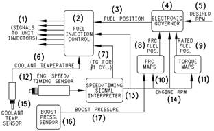
Illustration 5
Electronic governor
(1) Signals to the electronic unit injectors
(2) Fuel injection control
(3) Fuel position
(4) Electronic governor
(5) Desired rpm
(6) Coolant temperature
(7) TC for No. 1 cylinder
(8) FRC fuel position
(9) Rated fuel position
(10) FCR maps
(11) Torque maps
(12) Engine s peed/timing sensor
(13) Engine speed/timing signals’ interpreter
(14) Engine rpm
(15) Coolant temperature sensor
(16) Boost pressure sensor
(17) Boost pressure
The injection pump, the fuel lines, and the nozz les
that are used in the traditional Perkins diesel engines
hav e been replaced with an electronically controlled,
mechanically actuated electronic unit injector in each
cylinder. A solenoid on each injector controls the
amount of fuel that is delivered by the injector. An
Electronic Control Module (ECM) sends a signal to
eac h injector solenoid in order to provide complete
control of the engine.
This document has been printed from SPI². Not for Resale
![]() 10
10
Systems Operation Section
KENR6231
Fuel Injection
The ECM controls the amount of fuel that is injected
by varying the signals that are sent to the injectors.
The ECM s ends a high voltage signal to the solenoid
in order to energize the solenoid. The injec tors
will inject fuel only while the injector solenoid is
energized. By controlling the timing and the duration
of the voltage signal, the ECM can control injection
timing and the amount of fuel that is injected.
The ECM sets certain limits on the amount of fuel that
can be injected. “FRC” is a limit which controls the
amount of air and of fuel for the purpose of emission
control. This limit is based on the boost pressure.
When the ECM senses a higher boost pressure, the
ECM increases the “FRC” limit. “Rated Fuel Pos” is
a limit that is based on the horsepower rating of the
engine. This is similar to the rack stops and to the
torque spring on a mechanically governed engine.
“Rated Fuel Pos” provides horsepower and torque
curves for a specific engine family and for a specific
engine rating. All of these limits are programmed into
the personality module by the fac tory. These limits
are not programmable by the service technician.
Injection timing depends on three factors: the engine
speed (rpm), the engine load, and the operational
conditions of the engine. The ECM determines the
top center position of No. 1 cylinder from the signal
that is provided by the engine speed/timing sensor.
The ECM decides when the injection should occur
relative to the top center position. The ECM then
provides the signal to the electronic unit injector at
the desired time.
Electronic Unit Injector Mechanism
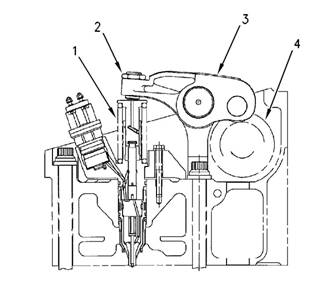
Illustration 6 g00291269
Electronic unit injector mechanism
(1) Electronic unit injector
(2) Adjusting nut
(3) Rocker arm assembly
(4) Camshaft lobe
The electronic unit injector mechanism provides
the downward force that is required to pressurize
the fuel in the electronic unit injector pump. The
electronic unit injector (1) allows fuel to be injected
into the combustion chamber with precise timing.
Movement is transmitted from the camshaft lobe (4)
for the electronic unit injector through the rocker arm
assembly (3) to the top of the electronic unit injector.
The adjusting nut (2) allows the injector lash to be
adjusted. For the proper setting of the injector lash,
refer to the topic on adjustment of the electronic unit
injector in Systems Operation, Testing and Adjusting,
“Electronic Unit Injector - Adjust”.
This document has been printed from SPI². Not for Resale
![]()
![]() KENR6231
KENR6231
Sy stems
11
Operation Section
Electronic Unit Injector
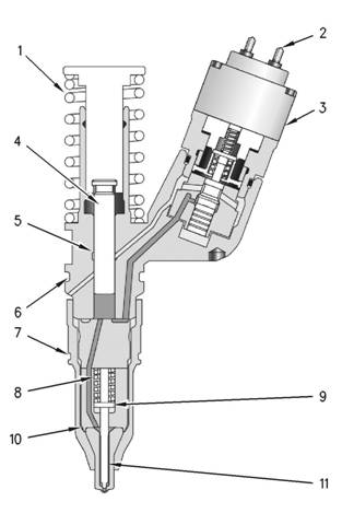
Illustration 7
Electronic unit injector
(1) Spring
g00984466
As the electronic unit injector mechanism transfers
the force to the top of the electronic unit injector,
spring (1) is compressed and plunger (4) is driven
downward. This ac tion displaces fuel through the
valve in solenoid valve assembly (3), and into the
return manifold to the fuel tank. As the plunger trav els
downward, the passage in barrel (5) is closed by the
outside diameter of the plunger. The passages within
body (10) and along check valve (11) to the injector
tip already contain fuel for injection. After the passage
in the plunger barrel is closed, the injector is ready for
injection at any time. The start of injection relies on
the software in the Electronic Control Module (ECM).
When the solenoid valve assembly is energized
from a signal across solenoid connection (2), the
valve closes and fuel pressure is elevated in the
injector tip. Injection begins at 34500 ± 1900 kPa
(5000 ± 275 psi) as the force of spring (8) above
spacer (9) is overcome. The check valve begins
to lift from the valve seat. The pressure continues
to rise as the plunger cycles through a full stroke.
After the correct amount of fuel has been disc harged
into the cylinder, the ECM removes the signal to the
solenoid connection. The solenoid valve assembly
is de-energized and the valve in the solenoid valve
assembly is opened. The high pressure fuel is then
dumped through the spill port and into the fuel return
manifold. The fuel is then returned to the fuel tank.
The check valve in the injector tip seats as the
pressure in the tip decreases.
The duration of injection meters the fuel that is
consumed during the fuel injection process. Injection
duration is controlled by the governor logic that is
programmed into the ECM.
As the camshaft lobe rotates past the point of
maximum lobe lift, the force on top of the electronic
(2) Solenoid connection to the Electronic Control Module (ECM)
(3) Solenoid valve assembly
(4) Plunger assembly
(5) Barrel
(6) Seal
(7) Seal
(8) Spring
(9) Spacer
(10) Body
(11) Check valve
Fuel at low pressure from the fuel supply manifold
enters the electronic unit injector at the fill port
through drilled passages in the cylinder head.
unit injector is removed and the spring for the injector
mechanism is allowed to expand. The plunger returns
to the original position. This uncovers the fuel supply
pas sage into the plunger barrel in order to refill the
injector pump body. The fuel at low pressure is again
allowed to circulate through the fuel injector body.
After circulating through the fuel injector body, the
fuel flows out of the spill port. This continues until the
solenoid valve assembly is re-energized for another
injection cycle.
This document has been printed from SPI². Not for Resale
![]()
![]()
![]() 12
12
Systems Operation Section
KENR6231
i02550062
Air Inlet and Exhaust System
Air is forced from the aftercooler into inlet manifold
(1). The air flow from the inlet port into the cylinders
is controlled by inlet valves .
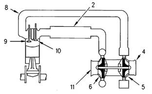
Illustration 8
Air inlet and exhaust system schematic
(1) Inlet to the engine
(2) Aftercooler core
(3) Inlet air line
(4) Exhaust outlet from turbocharger
(5) Turbine side of turbocharger
(6) Compressor side of turbocharger
(7) Air cleaner
g01046036
Illustration 9
Air inlet and exhaust system
(2) Aftercooler core
(4) Exhaust outlet
(5) Turbine side of turbocharger
(6) Compressor side of turbocharger
(8) Exhaust manifold
(9) Exhaust valve
(10) Inlet valve
(11) Air inlet
g00615497
The engine components of the air inlet and exhaust
system control the quality of air and the amount of
air that is available for combustion. The components
of the air inlet and exhaust system are the following
components:
• Air cleaner
• Turbocharger
• Aftercooler
• Cylinder head
• Valves and valve system components
• Piston and cylinder
• Exhaust manifold
The turbocharger compressor wheel pulls inlet air
through the air cleaner and into the air inlet. The air
is compressed and this causes the air to become hot.
The air flows through aftercooler core (2) and the
temperature of the compressed air lowers. This helps
to provide increased horsepower output. Aftercooler
core (2) is a separate cooler core that is mounted in
front of the engine radiator. The engine fan causes
ambient air to move across both cores. This cools the
turbocharged inlet air and the engine coolant.
Each cylinder has two inlet valves (10) and two
exhaust valves (9) in the cylinder head. The inlet
valves open on the inlet stroke. When the inlet valves
open, compressed air from the inlet port within the
inlet manifold is pushed into the cylinder. The inlet
valves c lose when the piston begins the compression
stroke. The air in the cylinder is compressed and the
fuel is injected into the cylinder when the piston is
near the top of the compression stroke. Combustion
begins when the fuel mixes with the air. The force of
combus tion pushes the piston on the power stroke.
The exhaust valves open and the exhaust gases
are pushed through the ex haust port into exhaust
manifold (8). After the piston finishes the exhaust
stroke, the exhaust valves close and the cycle begins
again.
Exhaust gases from the exhaust manifold flow
into the turbine side of turbocharger (5). The high
temperature exhaust gases cause the turbocharger
turbine wheel to turn. The turbine wheel is connected
to the shaft that drives the compressor wheel.
Exhaust gases from the turbocharger pass through
exhaust outlet (4), through a muffler, and through an
exhaust stack.
This document has been printed from SPI². Not for Resale
![]()
![]() KENR6231
KENR6231
Sy stems
13
Operation Section
Turbocharger
Valves And Valve Mechanism
Illustration 10
Turbocharger
(4) Air inlet
(5) Compressor housing
(6) Compressor wheel
(7) Bearing
(8) Oil inlet port
(9) Bearing
(10) Turbine housing
(11) Turbine wheel
(12) Exhaust outlet
g00291085
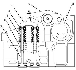
Illustration 11
Valve system components
(1) Valve bridge
(2) Rocker arm
(3) Camshaft
(4) Rotocoil
(5) Valve spring
(6) Valve guide
(7) Valve
g01046041
(13) Oil outlet port
(14) Exhaust inlet
Turbocharger (3) is mounted to exhaust manifold (2)
of the engine. All of the exhaust gases go from the
exhaust manifold through the turbocharger.
The exhaust gases enter the turbocharger and the
turbine wheel is turned. Because the turbocharger
turbine wheel is connected by a shaft to the
turbocharger compres sor wheel, the turbine wheel
and the compressor wheel turn at very high speeds.
The rotation of the compressor wheel pulls clean
air through the compressor housing air inlet. The
action of the compressor wheel blades causes a
compression of the inlet air. This compression allows
a larger amount of air to enter the engine. With more
air in the engine, the engine is able to burn more fuel.
The overall effect is an increase in power.
Bearing (7) and bearing (9) in the turbocharger use
engine oil that is under pressure for lubrication. The
lubrication for the bearings flows through oil inlet port
(8) and into the inlet port in the center section of the
turbocharger cartridge. The oil exits the turbocharger
through oil outlet port (13). The oil then returns to
the engine oil pan through the oil drain line for the
turbocharger.
The valves and the valve mechanism control the flow
of inlet air into the c ylinders during engine operation.
The valves and the valve mechanism control the flow
of exhaust gases out of the cylinders during engine
operation.
This document has been printed from SPI². Not for Resale
![]()
![]()
![]() 14
14
Systems Operation Section
KENR6231
Rotocoils (4) cause the valves to rotate while the
engine is running. Valve rotation provides a longer
service life. Valve rotation also minimizes carbon
deposits on the valves.
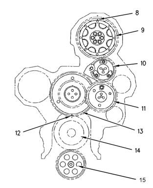
Adjustable idler gear (10) is designed to provide the
required gear backlash between nonadjustable idler
gear (11) and camshaft gear (9). If the cylinder head is
removed, tolerances of the components will change.
The components that change are the cylinder head
and the head gasket. The adjustable idler gear must
be relocated. For information on setting the correct
bac klash, refer to Systems Operation, Tes ting and
Adjusting, “Gear Group (Front) - Time”.
The camshaft drive gear has integral pendulums
which act as a vibration damper for the front gear
group. These pendulums are designed to counteract
the torsional forces from the injector pulses. This
eliminates vibration and noise. The engine also runs
smoother at all operating speeds.
Lubrication System
i02550074
Illustration 12
Components of the gear train
(8) Timing mark
(9) Camshaft gear
(10) Adjustable idler gear
(11) Idler gear
(12) Timing mark
(13) Cluster gear
(14) Crankshaft gear
(15) Oil pump gear
g01033757
Lubrication System Components
The lubrication system has the following components:
• Oil pan
• Oil pump
• Oil cooler
The inlet valves and the exhaust valves are opened
by the valve mechanism. The inlet valves and
the exhaust valves are also closed by the valve
mechanism. This occurs as the rotation of the
crankshaft causes camshaft (3) to rotate. Camshaft
gear (9) is driven by a series of two idler gears (10)
and (11). Idler gear (11) is driven by cluster gear (13).
Cluster gear (13) is driven by crankshaft gear (14).
Timing mark (12) and timing mark (8) are aligned in
order to provide the correct relationship between the
piston and the valve movement.
The camshaft has three lobes for each cylinder.
One lobe operates the inlet valves. A second lobe
operates the exhaust valves. The third lobe operates
the unit injector mechanism. The camshaft lobes turn
and the rocker arms move. Movement of the rocker
arms will make the inlet and ex haust valve bridges
move. These bridges allow one rocker arm to actuate
two valves at the same time. Each cylinder has two
inlet valves and two exhaust valves. Each valve has
one valve spring (5). The spring closes the valve.
•
•
•
Oil filter
Turbocharger oil lines
Oil passages for the cylinder block
This document has been printed from SPI². Not for Resale