 English
 Espaol
 Franais
 阿拉伯
阿拉伯 中文
中文 Deutsch
 Italiano
 Português
 日本
日本 韩国
韩国 български
 hrvatski
 esky
esky Dansk
Dansk Nederlands
 suomi
suomi Ελληνικ
 印度
印度 norsk
norsk Polski
 Roman
Roman русский
 Svenska
Perkins2506柴油发动机威尔逊P500E柴油发电机配件KRP3030活塞供应商,Perkins2506柴油发动机威尔逊P500E柴油发电机配件KRP3030活塞技术价格规格咨询服务,Perkins2506柴油发动机威尔逊P500E柴油发电机配件KRP3030活塞零配件供应,Perkins2506柴油发动机威尔逊P500E柴油发电机配件KRP3030活塞售后服务中心,Perkins2506柴油发动机威尔逊P500E柴油发电机配件KRP3030活塞,Perkins2506柴油发动机威尔逊P500E柴油发电机配件KRP3030活塞详细的技术参数,

产品中心
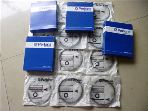
Perkins2506柴油发动机威尔逊P500E柴油发电机配件KRP3030活塞
详细描述
项目 零配件号码 新件号 描述
1 KRP3030 6 KRP3030 活塞装备
1 KRP3017 6 KRP3030 活塞装备
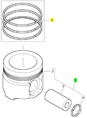
5 KRP3018 6 KRP3018 活塞环装备
5 KRP3019 6 KRP3018 活塞环装备
项目 零配件号码 新件号 描述
2 1 活塞
3 CH11503 1 CH11503 轴头销
4 CH11992 2 CH11992 CIRCLIP
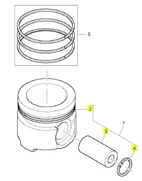
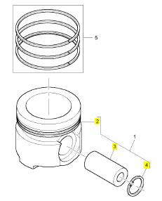
项目 零配件号码 新件号 描述
2 1 活塞
3 CH11503 1 CH11503 轴头销
4 CH11992 2 CH11992 CIRCLIP
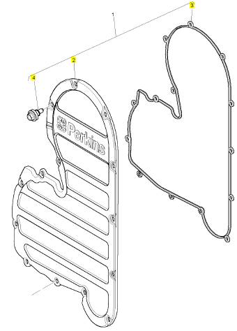
项目 零配件号码 新件号 描述
CH11352 1 CH11352 密封垫
1 TIMINGGEAR 盖
CH11976 14 CH10946
1 CH11848 1 CH11848 正时齿轮箱盖
1 CH11848 1 CH11848 正时齿轮箱盖
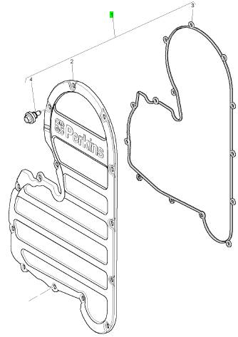
项目 零配件号码 新件号 描述
2 1 TIMINGGEAR 盖
3 CH11352 1 CH11352 密封垫
4 CH10946 14 CH10946 螺旋
4 CH11976 14 CH10946
项目 零配件号码 新件号 描述
1 CH11667 1 CH11667 正时齿轮箱
1 CH11615 1 CH11667 正时齿轮箱
2 CH10829 1 CH10829 密封垫 - 正时齿轮箱
3 CH10953 10 CH10953 图钉
4 CH10815 8 CH10815 螺拴
5 CH10255 8 CH10255 垫圈
5 CH10541 8 CH10255 垫圈
6 CH10791 9 CH10791 螺拴
6 CH11476 9 CH10791 螺拴
7 CH10832 1 CH10832 支撑托架
8 CH11895 2 CH11895 螺拴
8 CH10537 2 CH11895 螺拴
9 CH10615 2 CH10615 垫圈

Oil Flow Through The Oil Filter And Oil
Cooler
Illustration 13
Oil flow when the engine is warm.
(1) Oil manifold
(2) Oil supply line
(3) Oil return line
(4) Oil filter
(5) Bypass valve for the oil filter
(6) Oil pan
(7) Oil pump
(8) Bypass valve for the oil cooler
(9) Suction lines
(10) Oil cooler
g00562123
Illustration 14
Oil flow when the engine Is cold.
(1) Oil manifold
(2) Oil supply line
(3) Oil return line
(4) Oil filter
(5) Bypass valve for the oil filter
(6) Oil pan
(7) Oil pump
(8) Bypass valve for the oil cooler
(9) Suction lines
(10) Oil cooler
(11) Bypass valve for the oil pump
g00562383
(11) Bypass valve for the oil pump
When the engine is warm, oil is drawn from the oil
pan (6) through the suc tion lines (9) to the oil pump
(7). The oil pump pushes the hot oil through the oil
cooler (10). The oil is then sent to the oil filter (4).
Oil from the oil filter is sent to the oil manifold (1) in
the cylinder block and to the oil supply line (2) for the
turbocharger. Oil from the turbocharger goes back
through the oil return line (3) to the oil pan.
When the engine is cold, oil is drawn from the oil
pan (6) through the suction lines (9) to the oil pump
(7). When the oil is cold, an oil pressure differential
in the bypass valves causes the bypass valves to
open. These bypass valves then provide immediate
lubrication to all of the engine components when cold
oil with high viscosity causes a restriction to oil flow
through the oil cooler (10) and the oil filter (4). The oil
pump then pushes the cold oil through the bypass
valve (8) for the oil cooler and through the bypass
valve (5) for the oil filter. The oil then goes to the oil
manifold (1) in the cylinder block and to the supply
line (2) for the turbocharger. Oil from the turbocharger
goes back through the oil return line (3) to the oil pan.
When the oil is warm, an oil press ure differential in
the bypass valves also causes the bypass valves to
close. There is normal oil flow through the oil cooler
and the oil filter.
The by pass valves will also open when there is
a restriction in the oil cooler or the oil filter. This
prevents a restricted oil filter or a res tricted oil cooler
from stopping the lubrication of the engine. The
system pressure is limited by the oil pump bypass
valve (11).
This document has been printed from SPI². Not for Resale
![]()
![]()
![]() 16
16
Systems Operation Section
KENR6231
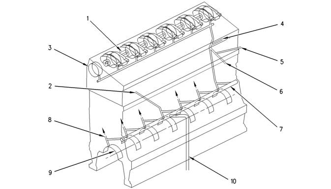
Oil Flow In The Engine
Illustration 15
Engine oil flow sc hematic
(1) Rocker arm shaft
(2) Oil passage to air compressor
(3) Camshaft bearing journals
(4) Oil passage to adjustable idler gear
(5) Oil passage to the fixed idler stub shaft
(6) Oil passage to cluster idler gear
(7) Oil manifold
(8) Pis ton cooling jet
(9) Crankshaft main bearings
(10) Oil passage from filter
g00431790
The oil from the oil manifold (7) is sent under
pressure through drilled passages to the crankshaft
main bearings (9). The oil flows through drilled holes
in the crankshaft. This oil lubricates the connecting
rod bearings. A small amount of oil is sent to the
piston cooling jets (8). The piston cooling jets spray
oil on the underside of the pistons.
Oil flows through passages in the timing gear housing
and the accessory drive gear. This oil flows to the air
compressor through the oil passage (2).
Oil passage (4) prov ides oil to the adjustable idler
gear. Oil passage (5) provides oil to the fixed idler
gear. Oil passage (6) provides oil to the cluster gear.
The oil flows through a passage in the shafts of the
gears.
There is a pressure control valve in the oil pump.
This valve controls the pressure of the oil that flows
from the oil pump.
Oil passage (9) provides lubrication to the rear
crankshaft seal. This ensures a long service life for
the rear crankshaft seal.
Oil flows into the cylinder head via a hollow locating
dowel in the top deck of the cylinder block. Oil trav els
to the camshaft bearing journals (3) and the three
center rocker arm shaft supports through drilled
passages in the cylinder head. The supports supply
oil to each rocker shaft. Oil flows to the bushings of
the fuel injec tor rocker arm through holes in the rocker
arm s haft (1). This same oil lubricates the valve and
the rollers. Oil flows through drilled passages in the
rocker arms. This oil lubricates the roller, the valve
bridge and the contact surfaces of the actuator of the
unit injector. Splash oil lubrication is used to lubricate
other components of the valve system.
Excess oil returns to the engine oil pan.
i02550118
Cooling System
This engine has a pressure type cooling system that
is equipped with a shunt line.
This document has been printed from SPI². Not for Resale
![]() KENR6231
KENR6231
Sy stems
17
Operation Section
|
advantages. First, the cooling system can be
operated safely at a temperature that is higher than
the boiling point of water. Next, cavitation in the water
pump is prevented. It is more difficult for air or steam
pockets to be made in the cooling system.
Note: Use Perkins ELC in an Air-To-Air Aftercooler
system. Refer to Operation and Maintenance Manual,
“Fluid Recommendations” for more information. This
keeps the temperature range of the coolant high
enough for efficient performance.
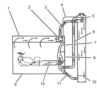
Illustration 16
Cooling system for a warm engine
(1) Cylinder head
(2) Water temperature regulator
(3) Outlet pipe
(4) Vent line
(5) Vent tube
(6) Shunt line
(7) Pipe
(8) Water pump
(9) Cylinder block
(10) Oil cooler
(11) Inlet pipe
(12) Radiator
In operation, the water pump (8) sends most of the
coolant from the radiator (12) to the oil cooler (10).
The coolant from the oil cooler (10) goes into the
cylinder block (9) through a bonnet and an elbow.
The coolant goes around the cylinder liners, through
the water directors and into the cylinder head.
The water directors send the flow of coolant around
the valves and the passages for exhaust gases in the
cylinder head. The coolant then goes to the front of
the cylinder head. At this point, water temperature
regulator (2) controls the direction of coolant flow.
The water temperature regulator (2) is c losed when
the engine is cold. The coolant flows through the
regulator housing and pipe (7) back to water pump
(8).
If the coolant is at normal operating temperature,
the water temperature regulator (2) opens and the
coolant flows to the radiator (12) through the outlet
pipe (3). The coolant becomes cooler as the coolant
moves through the radiator. When the coolant gets to
the bottom of the radiator, the coolant goes through
the inlet pipe (11) and into the water pump (8).
Note: The water temperature regulator (2) is an
important part of the cooling system. The water
temperature regulator (2) divides the coolant flow
between the radiator (12) and the bypass pipe (7).
This will maintain the correct temperature. If the
water temperature regulator is not installed in the
system, there is no mechanical control. Most of the
coolant will go through the bypass. This will cause
the engine to overheat in hot weather. If a higher
volume of c oolant goes through the radiator, the
engine will not reach normal operating temperatures.
This occurs during cold weather.
Shunt line (6) gives several advantages to the c ooling
system. The shunt line gives a positiv e coolant
pressure at the water pump inlet that prev ents pump
cavitation. A small flow of coolant constantly goes
through shunt line (6) to the inlet of water pump
(8). This causes a small amount of coolant to move
constantly through the vent tube (5). The flow through
the vent tube is small and the volume of the upper
compartment is large. Air in the coolant is removed
as the coolant goes into the upper compartment.
The vent line is used to fill the cooling system with
coolant for the first time. This will purge any air out of
the top of a bottom filled system.
i02550119
Basic Engine
Cylinder Block Assembly
Passages supply the lubrication for the crankshaft
bearings and the piston crowns. These passages
are cast into the cylinder block. Oil is supplied to the
pas sages by the cylinder block’s oil manifold.
The cylinder liner is an induction hardened liner. A
steel spacer plate provides improved reusability and
durability.
This document has been printed from SPI². Not for Resale
![]() 18
18
Systems Operation Section
KENR6231
Cylinder Head Assembly
The cylinder head is a one-piece cast iron head. The
cylinder head supports the camshaft. Steel reinforced
bearings are pressed into each bore. The bearings
are lubricated under pressure. Bridge dowels have
been eliminated as the valve train uses floating valve
bridges.
Thermal efficiency is enhanced by the use of
stainless steel thermal sleeves in each exhaust port.
The sleeves reduce the amount of heat rejection to
the cooling system. The sleeves then transfer the
thermal energy to the turbocharger.
The unit injector is mounted in a stainless steel
adapter. This adapter has been pressed into the
cylinder head injector bore.
Pistons, Rings And Connecting
Rods
The piston is a one-piece steel design that is retained
by the piston pin to the small end of the connecting
rod. The pistons have three rings that are located
in grooves in the steel crown. These rings seal the
combustion gas . The rings provide control of the oil.
The top ring has a barrel face. The second ring has
a tapered face and the ring has a coating of chrome
finish for the face. The third ring is the oil ring. The
third ring has a coil spring expander.
The connecting rod is a conventional design. The
cap of the connecting rod is attached to the shank by
two bolts that are threaded into the shank. Each side
of the small end of the connecting rod is machined
at an angle of 12 degrees in order to fit within the
piston cavity.
Crankshaft
The crankshaft converts the combustion force in the
cylinder into rotating torque. A v ibration damper is
used at the front of the crankshaft in order to reduce
the torsional vibrations.
The crankshaft drives a group of gears (front gear
train) on the front of the engine. The front gear
train provides power for the following components:
camshaft, water pump, oil pump, fuel transfer
pump, and accessory items that are specific to the
applic ation.
The cylinder block has seven main bearings that
support the crankshaft. The cylinder block uses two
bolts to hold each of the bearing caps to the block.
The crankcase uses a lip seal at both ends of the
crankshaft.
Camshaft
The camshaft has three lobes at each cylinder.
These lobes allow the camshaft to operate the unit
injector, the exhaust valves, and the inlet valves. The
camshaft is supported in the cylinder head by s even
journals which are fit with bearings. The camshaft
gear contains integral roller dampers that counteract
the torsional vibrations that are generated by the
high fuel pressure during fuel injector operation. The
des ign reduces gear train noise. The camshaft is
driven by an adjustable idler gear which is turned by
a fixed idler gear which is turned by a cluster idler
gear in the front gear train. Each bearing journal is
lubricated from the oil manifold in the cylinder head.
A thrust plate that is located at the front controls the
end play of the camshaft. Timing of the camshaft is
accomplished by aligning marks on the crankshaft
gear and idler gear, and camshaft gear with a mark
on the front timing plate.
i02554889
Electrical System
Grounding Practices
Proper grounding for the machine electrical sy stem
and engine electrical systems is necessary for
proper machine performance and reliability. Improper
grounding will res ult in uncontrolled electrical circuit
paths and unreliable electrical circuit paths.
Uncontrolled engine electrical circuit paths can result
in damage to main bearings, crankshaft bearing
journal surfaces, and aluminum components.
To ensure proper functioning of the vehicle and
engine electrical systems, an engine-to-frame ground
strap with a direct path to the negative battery post
must be used. This may be provided by way of a
starting motor ground, a frame to starting motor
ground, or a direct frame to engine ground.
An engine-to-frame ground strap must be used in
order to connect the grounding stud of the engine to
the frame of the vehicle and to the negative battery
post.
This document has been printed from SPI². Not for Resale
![]()
![]()
![]()
![]()
![]() KENR6231
KENR6231
Sy stems
19
Operation Section
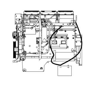
Illustration 17
Typical example
Grounding Stud To Battery Ground (“-”)
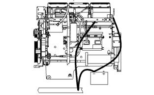
Illustration 18
Typical example
Alternate Grounding Stud To Battery Ground (“-”)
g01028488
g01028479
NOTICE
When boost starting an engine, the instructions in Op-
eration and Maintenance Manual, “Engine Starting”
should be followed in order to properly start the en-
gine.
This engine is equipped with a 24 volt starting system.
Only equal voltage for boost starting should be used.
The use of a higher voltage will damage the electrical
system.
The Electronic Control Module (ECM) must be dis-
connected at the “J1/P1” and “J2/P2” locations before
welding on the vehicle.
The engine has several input components which are
electronic. These components require an operating
voltage.
Unlike many electronic systems of the past, this
engine is tolerant to common external sources of
electrical noise. Buzzers that use electrical energy
can cause disruptions in the power supply. If buzz ers
are used anywhere on the machine, the engine
electronics should be powered directly from the
battery system through a dedicated relay. The engine
electronics should not be powered through a common
power bus with other keyswitch activated devices.
Engine Electrical System
The electrical system has the following separate
circuits :
• Charging
• Starting (If equipped)
• Accessories with low amperage
The charging circuit is in operation when the engine
is running. An alternator makes electricity for the
The engine must have a wire ground to the battery.
Ground wires or ground straps should be combined
at ground studs that are only for ground use. All of
the grounds should be tight and free of corros ion.
All of the ground paths must be capable of carrying
any likely current faults. An AWG #0 or larger wire is
recommended for the grounding strap to the cylinder
head.
The engine alternator should be battery ground
with a wire size that is capable of managing the full
charging current of the alternator.
charging circuit. A voltage regulator in the circuit
controls the electrical output in order to keep the
battery at full charge.
The starting circuit is activated only when the start
switch is activated.
Charging System Components
Alternator
The alternator is driven by a belt from the cranks haft
pulley. This alternator is a three-phase, self-rectifying
charging unit, and the regulator is part of the
alternator.
This document has been printed from SPI². Not for Resale
![]()
![]()
![]()
![]() 20
20
Systems Operation Section
KENR6231
The alternator design has no need for s lip rings
and the only part that has movement is the rotor
assembly. All conductors that carry current are
stationary. The following conductors are in the circuit:
• Field winding
• Stator windings
• Six rectifying diodes
• Regulator circuit components
The rotor assembly has many magnetic poles that
look like fingers with air space between each of the
opposite poles. The poles have residual magnetism.
The residual magnetism produces a small magnetic
field between the poles. As the rotor as sembly
begins to turn between the field winding and the
stator windings, a small amount of alternating current
(AC) is produced. The AC current is produced in the
stator windings from the small magnetic field. The
AC current is changed to direct current (DC) when
the AC current passes through the diodes of the
rectifier bridge. The current is used for the following
applications:
• Charging the battery
• Supplying the accessory circuit that has the low
amperage
• Strengthening the magnetic field
The first two applications use the majority of the
current. As the DC current increases through the
field windings, the s trength of the magnetic field is
increased. As the magnetic field becomes stronger,
more AC current is produced in the stator windings.
The increased speed of the rotor assembly also
increases the current and voltage output of the
alternator.
The voltage regulator is a solid-state electronic
switch. The voltage regulator senses the voltage in
the system. The voltage regulator switches ON and
OFF many times per second in order to control the
field current for the alternator. The alternator uses
the field current in order to generate the required
voltage output.
NOTICE
Never operate the alternator without the battery in the
circuit. Making or breaking an alternator connection
with heavy load on the circuit can cause damage to
the regulator.
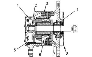
Illustration 19
Typical alternator components
(1) Regulator
(2) Roller bearing
(3) Stator winding
(4) Ball bearing
(5) Rectifier bridge
(6) Field winding
(7) Rotor assembly
(8) Fan
Starting System Components
Starting Solenoid
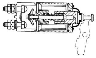
Illustration 20
Typical starting solenoid
g00425518
g00317613
This document has been printed from SPI². Not for Resale
![]()
![]() KENR6231
KENR6231
Sy stems
21
Operation Section
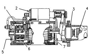
Illustration 21
Typical starting motor components
(1) Field
(2) Solenoid
(3) Clutch
(4) Pinion
(5) Commutator
(6) Brush assembly
(7) Armature
g00425521
When two sets of solenoid windings are used, the
windings are called the hold-in winding and the
pull-in winding. Both sets of windings have the same
number of turns around the cylinder, but the pull-in
winding uses a wire with a larger diameter. The wire
with a larger diameter produces a greater magnetic
field (1). When the start switch is closed, part of the
current flows from the battery through the hold-in
windings. The rest of the current flows through the
pull-in windings to the motor terminal. The current
then flows through the motor to ground. Solenoid
(2)is fully activated when the connection across the
battery and the motor terminal is complete. When
solenoid (2) is fully activated, the current is shut
off through the pull-in windings. At this point, only
the smaller hold-in windings are in operation. The
hold-in windings operate for the duration of time that
is required in order to start the engine. Solenoid (2)
will now draw less current from the battery, and the
heat that is generated by solenoid (2) will be kept at
an acceptable level.
The starting solenoid (2) is an electromagnetic s witch
that performs the following basic operations:
• The starting solenoid (2) closes the high current
starting motor circuit with a low current start switch
circuit.
• The starting solenoid (2) engages the pinion of the
starting motor (4) with the ring gear.
Solenoid (2) has windings (one or two sets) around
a hollow cylinder. A plunger that is spring loaded is
inside the cylinder. The plunger can move forward
and backward. When the start switch is closed and
electricity is sent through the windings, a magnetic
field (1) is made. The magnetic field (1) pulls the
plunger forward in the cylinder. This moves the shift
lever in order to engage the pinion drive gear with the
ring gear. The front end of the plunger then makes
contact across the battery and motor terminals of
solenoid (2). Next, the starting motor begins to turn
the flywheel of the engine.
When the start switch is opened, current no longer
flows through the windings. The spring now pushes
the plunger back to the original position. At the same
time, the spring moves the pinion gear away from
the flywheel.
This document has been printed from SPI². Not for Resale
| |||||||||||||||||||||
| |||||||||||||||||||||
Testing and Adjusting Section
KENR6231
Testing
Section
and
Adjusting
Testing
and
Adjusting
Belt
Tension Chart
i02555248
Table 1
|
Required Tools | |||
|
Tool |
Part Number |
Part Description |
Qty |
|
A |
- |
Belt Tension Gauge |
1 |
Table 2
Size of Belt
Width of Belt
(1)
(2)
Initial Belt Tension refers to a new belt.
Used Belt Tension refers to a belt that has been in operation for 30 minutes or more at the rated speed.
Install Tooling (A) at the center of the longest free
length of belt and check the tension on the belt.
Check and adjust the tension on the tightest belt.
To adjust the belt tension, refer to Disassembly and
Assembly, “Belt Tightener - Install”.
Note: When the belts are replaced, always replace
the belts as a set.
Table 3
Size of Belt
Width of Belt
(1)
(2)
Initial Belt Tension refers to a new belt.
Used Belt Tension refers to a belt that has been in operation for 30 minutes or more at the rated speed.
Install Tooling (A) at the center of the longest free
length of belt and check the tension on the belt.
Check and adjust the tension on the tightest belt.
To adjust the belt tension, refer to Disassembly and
Assembly, “Alternator - Install”.
This document has been printed from SPI². Not for Resale
![]() KENR6231
KENR6231
23
Testing and Adjusting Section
Fuel
System
i02550123
•
•
Relief valves
Check valves
Fuel System - Inspect
A problem with the components that send fuel to
the engine can cause low fuel pressure. This can
decrease engine performance.
1. Check the fuel level in the fuel tank. Ensure that
the v ent in the fuel cap is not filled with dirt.
2. Check all fuel lines for fuel leakage. The fuel lines
must be free from restrictions and faulty bends.
Verify that the fuel return line is not collapsed.
3. Install a new fuel filter.
4. Cut the old filter open with a suitable filter cutter.
Inspect the filter for excess contamination.
Determine the source of the contamination. Make
the necessary repairs.
5. Service the primary fuel filter (if equipped).
6. Operate the hand priming pump (if equipped).
If excessive resistance is felt, inspect the fuel
pressure regulating valv e. If uneven resistance
is felt, test for air in the fuel. Refer to Systems
Operation, Testing and Adjusting, “Air in Fuel -
Test” for more information.
7. Remove any air that may be in the fuel system.
Refer to Sy stems Operation, Testing and
Adjusting, “Fuel System - Prime”.
i02550146
Air in Fuel - Test
This procedure checks for air in the fuel. This
procedure also assists in finding the source of the air.
1. Examine the fuel system for leaks. Ensure that
the fuel line fittings are properly tightened. Check
the fuel level in the fuel tank. Air can enter the
fuel system on the suction side between the fuel
transfer pump and the fuel tank.
2. Install a suitable fuel flow tube with a visual sight
gauge in the fuel return line. When possible, install
the sight gauge in a straight section of the fuel line
that is at least 304.8 mm (12 inches) long. Do not
ins tall the sight gauge near the following devices
that c reate turbulence:
• Elbows
|
Look for air bubbles in the fuel. If there is no fuel
in the sight gauge, prime the fuel system. Refer to
System Operation, Testing and Adjusting, “Fuel
System - Prime” for more information. If the engine
starts, check for air in the fuel at varying engine
speeds. When possible, operate the engine under
the conditions which have been suspect of air in
the fuel.
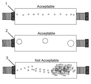
Illustration 22
(1) A steady stream of s mall bubbles with a diameter of
approximately 1.60 mm (0.063 inch) is an acceptable amount
of air in the fuel.
(2) Bubbles with a diameter of approximately 6.35 mm (0.250 inch)
are also acceptable if there is two sec onds to three seconds
intervals between bubbles.
(3) Excessive air bubbles in the fuel are not acceptable.
3. If excessive air is seen in the sight gauge in the
f, uel return line, install a second s ight gauge at the
inlet to the fuel transfer pump. If a second sight
gauge is not available, move the sight gauge from
the fuel return line and install the sight gauge
at the inlet to the fuel transfer pump. Observe
the fuel flow during engine crank ing. Look for air
bubbles in the fuel. If the engine starts, check for
air in the fuel at varying engine speeds.
If excessive air is not seen at the inlet to the fuel
transfer pump, the air is entering the system after
the fuel transfer pump. Proc eed to Step 6.
If excessive air is seen at the inlet to the fuel
transfer pump, air is entering through the suction
side of the fuel system.
This document has been printed from SPI². Not for Resale
![]()
![]()

![]() 24
24
Testing and Adjusting Section
KENR6231
To avoid personal injury, always wear eye and face
protection when using pressurized air.
4. Pressurize the fuel tank to the recommendations
of the OEM in order to avoid damage to the fuel
tank. Check for leaks in the fuel lines between
the fuel tank and the fuel transfer pump. Repair
any leaks that are found. Check the fuel pressure
in order to ensure that the fuel transfer pump is
operating properly. For information about checking
the fuel pressure, see System Operation, Testing
and Adjusting, “Fuel System Pressure - Test”.
5. If the source of the air is not found, disconnec t
the s upply line from the fuel tank and connect an
external fuel supply to the inlet of the fuel transfer
pump. If this corrects the problem, repair the fuel
tank or the stand pipe in the fuel tank.
6. If the injector sleev e is worn or damaged,
combustion gases may be leaking into the fuel
system. Also, if the O-rings on the injector sleeves
are worn, missing, or damaged, combustion gases
may leak into the fuel system.
i02550152
Electronic Unit Injector - Adjust
Table 4
Required Tools
Tool Part Number Part Description Qty
A CH11149 Injector Height Gauge 1
To make an adjustment to the unit injectors on
cylinders 3, 5, and 6 us e the following procedure:
1. Put the No. 1 piston at the top center position
on the compression stroke. Refer to Systems
Operation, Testing and Adjusting, “Finding Top
Center Position for No. 1 Piston”.
2. Use Tooling (A) in order to obtain a dimension of
78.0 ± 0.2 mm (3.07 ± 0.01 inch). The dimension
is measured from the top of the unit injector to the
machined ledge of the fuel injector body.
3. Turn the adjusting screw for the unit injector (2)
cloc kwise until the correct height is obtained.
4. Hold the adjusting screw in this position and
tighten locknut (3) to a torque of 100 ± 10 N·m
(74 ± 7 lb ft).
5. To make an adjustment to the unit injectors on
cylinders 1, 2, and 4, remove the timing bolt. Turn
the flywheel by 360 degrees in the direction of
engine rotation. The direction of engine rotation is
counterclockwise, as the engine is viewed from
the flywheel end. This will put the number 1 piston
at the top center position on the exhaust stroke.
6. Repeat Steps 3 through 4.
7. Remove the timing bolt from the flywheel after all
the unit injector adjustments have been made.
Reinstall the valve mechanism cover.
i02550163
Electronic Unit Injector - Test
This procedure assists in identifying the cause for
an injector misfiring. Perform this procedure only
after performing the Cylinder Cutout Test. Refer to
Troubleshooting for more information.
1. Check for air in the fuel, if this procedure has
not already been performed. Refer to Systems
Operation, Testing and Adjusting, “Air in Fuel -
Test”.
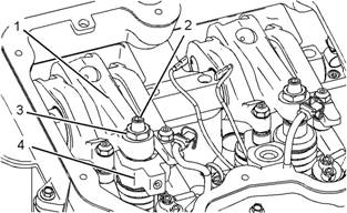
Illustration 23
Injector Mechanism (Typical example)
(1) Rocker arm
(2) Adjusting screw
(3) Locknut
(4) CH11149 Injector Height Gauge
g01023138
Electrical shock hazard. The electronic unit injec-
tor system uses 90-120 volts.
This document has been printed from SPI². Not for Resale
| |||||||||||||||||
25
Testing and Adjusting Section
2.
Remove the valve cover and look for broken
parts. Repair any broken parts or replace any
broken parts that are found. Inspect all wiring to
the solenoids. Look for loos e connections. Also
Finding
Top
Center
i02551444
Position
look for frayed wires or broken wires. Ens ure
that the connector for the unit injector solenoid
is properly connected. Perform a pull test on
each of the wires. Refer to Troubleshooting,
“Elec trical Connectors - Inspect”. Inspect the pos ts
of the solenoid for arcing. If arcing or evidence
of arcing is found, remove the cap assembly.
Refer to Disassembly and Assembly, “Elec tronic
Unit Injector - Remove”. Clean the connecting
posts. Reinstall the cap assembly and tighten
the solenoid nuts to a torque of 2.5 ± 0.25 N·m
(22 ± 2 lb in). Refer to Disassembly and Assembly ,
for No. 1
Table 5
Piston
3.
4.
5.
6.
“Electronic Unit Injector - Install”.
Check the valve lash setting for the cylinder of the
suspect unit injector. Refer to Systems Operation,
Testing and Adjusting, “Engine Valve Lash -
Inspect/Adjust”.
Ensure that the bolt that holds the unit injector is
tightened to the proper torque. If necessary, loosen
the bolt that holds the unit injector and tighten the
bolt to a torque of 55 ± 10 N·m (40.6 ± 7.4 lb ft).
Remove the suspect unit injector and check the
unit injector for signs of exposure to coolant. Refer
to Disassembly and Assembly, “Electronic Unit
Injector - Remove”. Exposure to coolant will cause
rust to form on the injec tor. If the unit injector
shows signs of exposure to coolant, remove the
injector sleev e and inspect the injector sleeve.
Refer to Disassembly and Assembly, “Elec tronic
Unit Injector Sleeve - Remove”. Replace the
injector sleeve if the injector sleeve is damaged.
Check the unit injector for an exc essive brown
dis coloration that extends beyond the injector tip. If
excessive discoloration is found, check the quality
of the fuel. Refer to Systems Operation, Testing
and Adjusting, “Fuel Quality - Test”. Replace the
seals on the injector and reinstall the injector.
Refer to Disassembly and Assembly, “Elec tronic
Unit Injector - Install”. Also refer to Disassembly
and Assembly, “Electronic Unit Injector Sleeve -
Install”.
If the problem is not resolved, replace the suspect
injector with a new injector.
|
compression stroke is the starting point of all timing
procedures.
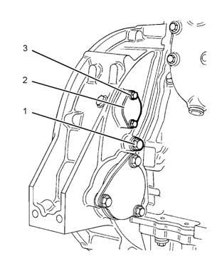
Illustration 24
Typical example
1. Remove both bolts (3) and cover (2) from the
flywheel housing. Remove the plug (1) from the
timing hole in the flywheel hous ing.
2. Install Tooling (A) into the flywheel housing
through the aperture behind the cover (2). Tooling
(A) is used in order to turn the engine flywheel in
the direction of normal engine rotation. Normal
engine rotation is counterclockwise. Normal
engine rotation is viewed from the flywheel end of
the engine. Turn the engine flywheel until Tooling
(B) engages with the threaded hole in the flywheel.
This document has been printed from SPI². Not for Resale