 English
 Espaol
 Franais
 阿拉伯
阿拉伯 中文
中文 Deutsch
 Italiano
 Português
 日本
日本 韩国
韩国 български
 hrvatski
 esky
esky Dansk
Dansk Nederlands
 suomi
suomi Ελληνικ
 印度
印度 norsk
norsk Polski
 Roman
Roman русский
 Svenska
Perkins2506柴油发动机威尔逊P500E柴油发电机配件汽缸盖垫供应商,Perkins2506柴油发动机威尔逊P500E柴油发电机配件汽缸盖垫技术价格规格咨询服务,Perkins2506柴油发动机威尔逊P500E柴油发电机配件汽缸盖垫零配件供应,Perkins2506柴油发动机威尔逊P500E柴油发电机配件汽缸盖垫售后服务中心,Perkins2506柴油发动机威尔逊P500E柴油发电机配件汽缸盖垫,Perkins2506柴油发动机威尔逊P500E柴油发电机配件汽缸盖垫详细的技术参数,

产品中心
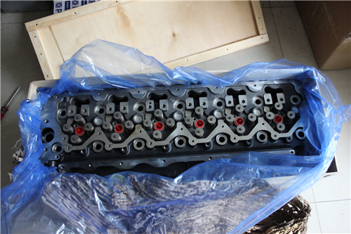
Perkins2506柴油发动机威尔逊P500E柴油发电机配件汽缸盖垫
详细描述
项目 零配件号码 新件号 描述
1 CH11399 1 CH11399 汽缸盖组合
1 CH11399 1 CH11399 汽缸盖组合
(1) CH11399 1 CH11399 汽缸盖装备 -EXCH
(1) CH11399 1 CH11399 汽缸盖装备 -EXCH
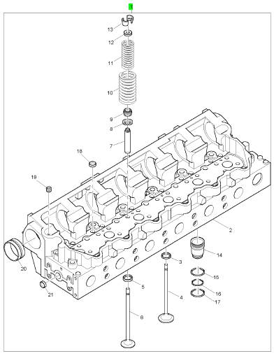
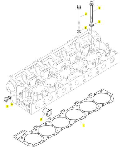
项目 零配件号码 新件号 描述
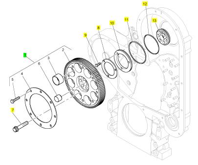
1 1 密封垫 - 汽缸盖
2 CH10712 16 CH10712 螺拴
3 CH10711 16 CH10711 垫圈
4 CH10713 10 CH10713 螺拴
5 CH10711 10 CH10711 垫圈
6 CH10708 6 CH10708 套筒
7 CH10286 3 CH10286 栓塞
8 CH10133 3 CH10133 密封O型圈
项目 零配件号码 新件号 描述
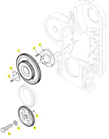
1 CH11526 1 CH11526 惰轮传动机构
1 CH10963 1 CH10963 惰轮传动机构
2 CH10876 1 CH10876 螺木桩
3 CH10611 5 CH10611 螺拴
4 CH10619 1 CH10619 推力板
5 CH10621 4 CH10621 螺拴
6 CH10622 1 CH10622 油泵传动机构
7 CH10005 1 CH10005 半圆键
8 CH10609 1 CH10609 螺拴
9 CH10610 1 CH10610 垫圈
项目 零配件号码 新件号 描述
1 T400235 1 T400235 凸轮轴传动机构
1 CH10910 1 T400235 凸轮轴传动机构
7 CH10616 6 CH10616 螺拴
8 CH10617 1 CH10617 推力板
9 CH10618 3 CH10618 螺拴
10 CH10625 1 CH10625 密封垫
11 CH10620 1 CH10620 密封O型圈
12 CH10612 1 CH10612 密封O型圈
13 CH10627 1 CH10627 承接器
项目 零配件号码 新件号 描述
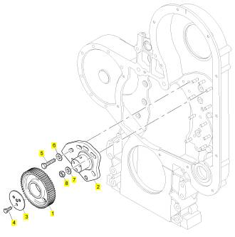
1 CH10635 1 CH10635 惰轮传动机构
2 CH10623 1 CH10623 螺木桩
3 CH10614 1 CH10614 推力板
4 CH10621 3 CH10621 螺拴
5 CH10609 1 CH10609 螺拴
6 CH10615 1 CH10615 垫圈
7 CH10615 5 CH10615 垫圈
8 CH10290 5 CH10798 螺帽
项目 零配件号码 新件号 描述
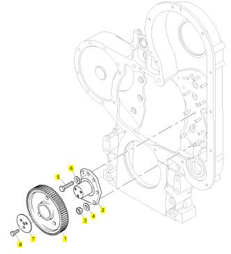
1 CH10632 1 CH10632 惰轮传动机构
2 CH10624 1 CH10624 螺木桩
3 CH10290 5 CH10798 螺帽
4 CH10615 5 CH10615 垫圈
5 CH10609 1 CH10609 螺拴
6 CH10615 1 CH10615 垫圈
7 CH10614 1 CH10614 推力板
8 CH10621 3 CH10621 螺拴
项目 零配件号码 新件号 描述
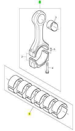
1 CH11507 6 CH11507 连杆组合
6 KRP3016 1 KRP3016 大头轴承装备
(6) KRP3016/064 1 KRP3016/064 大头 BRG 装备 -U/S
(6) KRP3016/127 1 KRP3016/127 大头 BRG 装备 -U/S
Note: If the flywheel is turned beyond the point
of engagement, the flywheel must be turned in
the opposite direction of normal engine rotation
approximately 45 degrees. Then turn the flywheel in
the direction of normal rotation until the timing bolt
engages with the threaded hole. The procedure will
eliminate the backlash that will occur when the No. 1
piston is put on the top center.
3. Remove the front valve mechanism cover from
the engine.
4. The inlet and exhaust valves for the No. 1 cylinder
are fully closed if the No. 1 piston is on the
compression stroke and the rocker arms can be
moved by hand. If the roc ker arms can not be
moved and the valves are slightly open the No. 1
pis ton is on the exhaust stroke.
Note: After the actual stroke position is identified,
and the other s troke position is needed, remove the
timing bolt from the flywheel. The flywheel is turned
360 degrees in a counterclockwise direction. The
3.
Refer to Operation and Maintenance Manual,
“Fuel Recommendations” for more information.
If fuel quality is still suspected as a possible
cause to problems regarding engine performance,
dis connect the fuel inlet line, and temporarily
operate the engine from a separate source of
fuel that is known to be good. This will determine
if the problem is caused by fuel quality. If fuel
quality is determined to be the problem, drain the
fuel system and replace the fuel filters. Engine
performance can be affected by the following
characteristics:
• Cetane number of the fuel
• Air in the fuel
• Other fuel characteristics
i02551471
timing bolt is reinstalled.
Fuel System - Prime
Fuel Quality - Test
i02551477
NOTICE
Use a suitable container to c atch any fuel that might
spill. Clean up any spilled fuel immediately.
Ensure that all adjustments and repairs are performed
by authorized personnel that have had the correct
training.
Use the following procedure to test for problems
regarding fuel quality:
1. Determine if water and/or contaminants are
present in the fuel. Check the water separator (if
equipped). If a water separator is not present,
proceed to Step 2. Drain the water separator, if
neces sary. A full fuel tank minimizes the potential
for overnight condensation.
Note: A water separator can appear to be full of fuel
when the water separator is actually full of water.
2. Determine if contaminants are present in the
fuel. Remove a sample of fuel from the bottom
of the fuel tank. Visually inspect the fuel sample
for contaminants. The color of the fuel is not
necessarily an indication of fuel quality. However,
fuel that is black, brown, and/or similar to sludge
can be an indication of the growth of bacteria or
oil contamination. In cold temperatures, cloudy
fuel indicates that the fuel may not be suitable for
operating conditions.
NOTICE
Do not allow dirt to enter the fuel system. Thoroughly
clean the area around a fuel system component that
will be disconnected. Fit a suitable cover over discon-
nec ted fuel system component.
Note: This procedure is most common when the
engine has run out of fuel.
1. Turn the ignition switch to the “OFF” position.
2. Fill the fuel tank(s) with clean diesel fuel.
This document has been printed from SPI². Not for Resale
![]()
![]()
![]()
![]() KENR6231
KENR6231
27
Testing and Adjusting Section
•
The engine starts, but the engine continues to
misfire or smoke.
9.
Run the engine with no load until the engine runs
smoothly.
i02571703
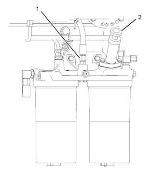
Fuel System Pressure - Test
Illustration 25
Typical example
g01282239
|
|
Low fuel pressure can cause low power. Low fuel
pressure can also cause cavitation of the fuel
which can damage the fuel injectors. The following
conditions can cause low fuel pressure:
• Plugged fuel filters
pump
• Debris in the pressure regulating valve
• Partially open check valve
the fuel transfer pump
3.
Loosen the union of the pipe for the fuel(1).
•
Severe wear on return fuel pressure regulating
valve in the fuel filter base
Note: Do not remove the union completely. Open the
union enough to allow the air that is trapped in the
cylinder head to be purged from the fuel system.
4. Unlock and operate the hand priming pump (2).
Use a suitable container to collect excess fuel.
5. Tighten the union of the pipe for the fuel (1).
6. Operate the hand priming pump until a strong
pressure is felt on the pump. Push the priming
pump plunger inward. Tighten the plunger by hand
and s tart the engine.
NOTICE
Do not crank the engine continuously for more than
30 seconds. Allow the starting motor to cool for 30
•
•
•
•
•
•
Worn gears in the fuel transfer pump
Pinched fuel lines or undersized fuel lines
Old fuel lines that have a reduced interior diameter
that was caused by swelling
Fuel lines with deteriorating interior surfaces
Pinched fuel line fittings or undersized fuel line
fittings
Debris in the fuel tank, fuel lines, or fuel system
components that create restrictions
|
7. If the engine will not start, allow the starting motor
to cool for 30 seconds. Repeat steps 3 to 6 in
order to operate the engine.
8. Continue to eliminate air from the fuel system if
these events occ ur:
evenly.
High Fuel Pressure
Excessive fuel pressure can cause fuel filter gaskets
to rupture. The following conditions can cause high
fuel pressure:
• Plugged orifices in the fuel pressure regulating
valve
• Stuck fuel pressure regulating valve in the fuel
transfer pump
• Pinched fuel return line
This document has been printed from SPI². Not for Resale

![]() 28
28
Testing and Adjusting Section
KENR6231
Checking Fuel Pressure
Table 6
Gear Group (Front) - Time
i02551488
Tool
A
Required Tools
Part Number Part Description
- Pressure Gauge
Qty
1
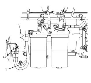
Illustration 26
g01288627
To check the fuel transfer pump pressure, remove
the hose assembly (1). Install a pressure gauge, and
start the engine.
Fuel Pressure Readings
The typical fuel pressure of the engine at operating
temperature c an vary. When the engine is under
load, the fuel pressure can be 550 kPa (80 psi).
The performance of the unit injector deteriorates
when the fuel pressure drops below 241 kPa (35 psi).
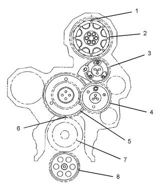
Illustration 27
Front gear group
(1) Timing marks
(2) Camshaft gear
(3) Adjustable idler gear
(4) Idler gear
(5) Cluster gear
(6) Timing marks
(7) Crankshaft gear
(8) Oil pump gear
g01097754
Low power complaints and erratic operation can
occur in this situation. Check for a plugged fuel filter
or air in the fuel lines as possible causes for these
complaints before replacing fuel system components.
The basis for the correct fuel injection timing and
the v alve mechanism operation is determined by
the alignment of the timing for the front gear group.
Timing marks (1) through timing marks (6) are aligned
in order to provide the c orrect relationship between
the piston movement and the valve movement.
This document has been printed from SPI². Not for Resale
| |||||||||||||||||||||
29
Testing and Adjusting Section
Setting
Backlash
For Camshaft
And Adjustable Idler Gear
Table 7
B
1.
Remove the front cover. Refer to Disassembly and
Assembly, “Housing (front) - Remove”.
Note: Ensure that No. 1 pis ton is at the top center
position. Refer to Systems Operation, Testing and
Adjusting, “Finding Top Center Position for No. 1
Piston”.
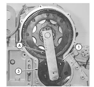
Illustration 29
Typical example
Installation of the adjustable idler assembly
(A) Cams haft Alignment tool
(1) Nuts
(3) Bolt
g00294873
3.
Refer to Illustration 29 in order to position Tooling
(A). Move Tooling (A) to the left and to the right.
Lightly tighten nuts (1) and bolt (3). Once the nuts
and the bolt are tightened, lightly tap Tooling (A)
with a rubber mallet on the sides. This will ensure
that the tool is properly seated. Tooling (A) should
be free to move in and out without any binding.
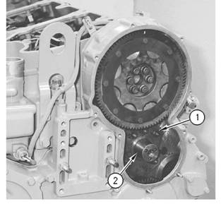
Illustration 28
Typical example
Loosen stub shaft assembly.
(1) Nuts
(2) Stub shaft
g00294872
2.
Remove the adjus table idler gear from stub shaft
(2). Stub shaft (2) is held in position with five nuts
(1) and one bolt. Loosen five nuts (1) and loosen
the one bolt.
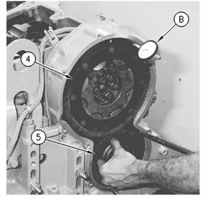
Illustration 30
Typical example
Checking backlash
(B) Indicator assembly
(4) Camshaft gear
(5) Idler gear assembly
g00294874
This document has been printed from SPI². Not for Resale
![]() 30
30
Testing and Adjusting Section
KENR6231
4.
5.
6.
7.
Install Tooling (B) on the timing gear housing.
Loosely install the idler gear assembly (5) to the
timing gear housing. When idler gear assembly
(5) is held stationary, the bac klash between
the camshaft gear (4) and the idler gear (5) is
0.216 ± 0.114 mm (0.0085 ± 0.0045 inch).
If necessary, repeat step 2 through step 4 in order
to obtain the proper backlash.
Tighten the nuts and the bolt. Refer to Disassembly
and Assembly, “Gear Group (Front) - Install” for
the correct procedure.
Install the front cover. Refer to Disassembly and
Assembly, “Housing (Front) - Install”.
This document has been printed from SPI². Not for Resale
![]()
![]()
![]()
![]()
![]() KENR6231
KENR6231
31
Testing and Adjusting Section
Air
Inlet
and
Exhaust
Syst em
Air
Inlet and
i02581541
Exhaust System
-
Inspect
A general visual inspection should be made to the air
inlet and exhaust system. Make sure that there are
no signs of leaks in the system.
Table 8
|
Required Tools | |||
|
Tool |
Part Number |
Part Description |
Qty |
|
A |
- |
Differential Pressure Gauge |
1 |
Air Inlet Restriction
There will be a reduction in the performance of the
engine if there is a restriction in the air inlet system.
1. Inspect the engine air cleaner inlet and ducting
in order to ensure that the passageway is not
blocked or collapsed.
2. Inspect the engine air cleaner element. Replace
a dirty engine air cleaner element with a clean
engine air cleaner element.
3. Check for dirt tracks on the clean side of the
engine air cleaner element. If dirt tracks are
observed, contaminants are flowing past the
engine air cleaner element and/or the seal for the
engine air cleaner element.
Hot engine
components
can cause
injury
from
burns.
Before
performing
maintenance
on
the
engine, allow the engine and the components to
cool.
Making contact with a running engine can cause
burns from hot parts and can cause injury from
rotating parts.
When working on an engine that is running, avoid
contact with hot parts and rotating parts.
4. Use Tooling (A) for this test.
This document has been printed from SPI². Not for Resale
![]()
![]()
![]()
![]() 32
32
Testing and Adjusting Section
KENR6231
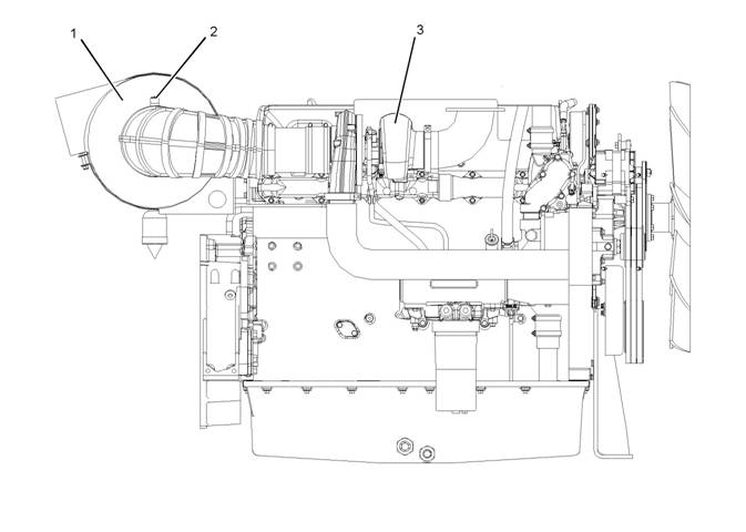
Illustration 31
Air inlet piping
(1) Air Cleaner
(2) Test location
(3) Turbocharger
g01293044
a.
Connect the v acuum port of the differential
pressure gauge to test location (2). Test
location (2) may be located anywhere along the
air inlet piping after air cleaner (1) but before
turbocharger (3).
Maximum restriction ........ 6.2 kPa (25 in of H2O)
The air flow through a new engine air cleaner element
must not have a restriction of more than the following
amount:
Maximum restriction ........ 3.7 kPa (15 in of H2O)
b. Leave the pressure port of the differential
pressure gauge open to the atmosphere.
c. Start the engine. Run the engine at full load.
d. Record the value.
e. Compare the result from step 4.d to the
appropriate values that follow.
The air flow through a used engine air cleaner
may have a restriction. The air flow through a
Turbocharger - Inspect
Hot engine components can cause
i02551491
injury from
plugged engine air cleaner will be restricted to some
burns.
Before
performing
maintenance
on
the
magnitude. In either case, the restriction must not be
more than the following amount:
engine, allow the engine and the components to
cool.
This document has been printed from SPI². Not for Resale
![]()
![]()
![]()
![]() KENR6231
KENR6231
33
Testing and Adjusting Section
Personal injury can result from rotating and mov-
ing parts.
Stay clear of all rotating and moving parts.
Never attempt adjustments while the machine is
moving or the engine is running unless otherwise
specified.
The machine must be parked on a level surface
and the engine stopped.
NOTICE
Keep all parts clean from contaminants.
Contaminants may cause rapid wear and shortened
component life.
NOTICE
Care must be taken to ensure that fluids are contained
during performance of inspection, maintenance, test-
ing, adjusting and repair of the product. Be prepared to
collect the fluid with suitable containers before open-
ing any compartment or disassembling any compo-
nent containing fluids.
Dispose of all fluids according to local regulations and
mandates.
Before you begin inspection of the turbocharger,
be sure that the inlet air restriction is within the
specifications for your engine. Be sure that the
exhaust system restriction is within the specifications
for your engine. Refer to Systems Operation, Testing
and Adjusting, “Air Inlet and Exhaust System -
Inspect”.
The condition of the turbocharger will have definite
effects on engine performance. Use the following
inspections and procedures to determine the
condition of the turbocharger.
• Inspection of the Compressor and the Compressor
Housing
• Inspection of the Turbine Wheel and the Turbine
Housing
1.
2.
3.
4.
Inspect the compressor wheel for damage from a
foreign object. If there is damage, determine the
source of the foreign object. As required, clean
the inlet system and repair the intake system.
Replace the turbocharger. If there is no damage,
go to Step 3.
Clean the compressor wheel and clean the
compressor housing if you find buildup of foreign
material. If there is no buildup of foreign material,
go to Step 3.
Turn the rotating assembly by hand. While you
turn the assembly, push the assembly sideways .
The assembly should turn freely. The compressor
wheel should not rub the compress or housing.
Replace the turbocharger if the compressor wheel
rubs the compressor wheel housing. If there is no
rubbing or scraping, go to Step 4.
Inspect the compressor and the compressor
wheel housing for oil leakage. An oil leak from
the compressor may deposit oil in the aftercooler.
Drain and c lean the aftercooler if you find oil in
the aftercooler.
a. Check the oil level in the crankcase. If the oil
level is too high, adjust the oil level.
b. Inspect the air cleaner element for restriction. If
restriction is found, correct the problem.
c. Inspect the engine crankcase breather. Clean
the engine crankcase breather or replace
the engine crankcase breather if the engine
crankc ase breather is plugged.
d. Remove the oil drain line for the turbocharger.
Inspect the drain opening. Inspect the oil drain
line. Inspect the area between the bearings of
the rotating assembly shaft. Look for oil sludge.
Inspect the oil drain hole for oil sludge. Inspect
the oil drain line for oil sludge in the drain
line. If neces sary, clean the rotating assembly
shaft. If necessary, clean the oil drain hole. If
necessary, clean the oil drain line.
e. If Steps 4.a through 4.d did not reveal the
source of the oil leakage, the turbocharger has
internal damage. Replace the turbocharger.
Inspection of the Compressor and
the Compressor Housing
Remove air piping from the compressor inlet.
Inspection of the Turbine Wheel
and the Turbine Housing
Remove the air piping from the turbine housing.
This document has been printed from SPI². Not for Resale
| |||||||||||||
Testing and Adjusting Section
KENR6231
a.
Remove the oil drain line for the turboc harger.
Inspect the drain opening. Inspect the area
between the bearings of the rotating assembly
shaft. Look for oil s ludge. Inspect the oil drain
hole for oil sludge. Inspect the oil drain line
for oil sludge. If necessary, clean the rotating
assembly shaft. If necessary, clean the drain
opening. If necessary, clean the drain line.
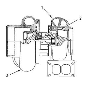
Illustration 32
Typical example
(1) Turbine Housing
(2) Turbine Wheel
(3) Turbocharger
g00763164
b. If crankcase pressure is high, or if the oil drain
is restricted, pressure in the center housing
may be greater than the pressure of turbine
housing (1). Oil flow may be forced in the wrong
direction and the oil may not drain. Check the
crankc ase pressure and correct any problems.
c. If the oil drain line is damaged, replace the oil
drain line.
d. Check the routing of the oil drain line. Eliminate
any sharp restrictive bends. Make sure that
the oil drain line is not too close to the engine
exhaust manifold.
e. If Steps 4.a through 4.d did not reveal the
source of the oil leakage, turbocharger (3) has
internal damage. Replace turbocharger (3).
1.
2.
3.
4.
Inspect the turbine for damage by a foreign object.
If there is damage, determine the source of the
foreign object. Replace turbocharger (3). If there
is no damage, go to Step 2.
Inspect turbine wheel (2) for buildup of carbon and
other foreign material. Inspect turbine housing (1)
for buildup of carbon and foreign material. Clean
turbine wheel (2) and clean turbine housing (1) if
you find buildup of carbon or foreign material. If
there is no buildup of carbon or foreign material,
go to Step 3.
Turn the rotating assembly by hand. While you
turn the assembly, push the assembly sideways.
The assembly should turn freely. Turbine wheel (2)
should not rub turbine wheel housing (1). Replace
turbocharger (3) if turbine wheel (2) rubs turbine
housing (1). If there is no rubbing or scraping, go
to Step 4.
Inspect the turbine and turbine housing (1) for oil
leakage. Inspect the turbine and turbine housing
(1)for oil coking. Some oil coking may be cleaned.
Heavy oil coking may require replacement of
the turbocharger. If the oil is coming from the
turboc harger center housing go to Step 4.a.
Otherwise go to “Inspection of the Wastegate”.
i02571444
Exhaust Temperature - Test
Table 9
When the engine runs, the temperature of an exhaust
manifold port can indicate the condition of a fuel
injection nozzle.
A low temperature indicates that no fuel is flowing to
the cylinder. An inoperative fuel injection nozzle or
a problem with the fuel injection pump could caus e
this low temperature.
A very high temperature can indicate that too much
fuel is flowing to the cylinder. A malfunctioning
fuel injection nozzle could cause this very high
temperature.
Use the Tooling (A) to check exhaust temperature.
This document has been printed from SPI². Not for Resale
![]()
![]()
| |||||||||||||
| ||||||||||||||||
35
Testing and Adjusting Section
Engine
Crankcase
i02571687
Pressure
This engine uses high voltage to control the fuel
(Blowby) - Test
Table 10
Damaged pistons or rings can cause too much
pressure in the crankcase. This condition will cause
the engine to run rough. There will be more than the
normal amount of fumes (blowby) rising from the
crankcase breather. The breather can then become
restricted in a very short time, causing oil leakage
at gaskets and seals that would not normally have
leakage. Blowby can also be caused by worn valve
guides or by a failed turbocharger seal.
Install Tooling (A) to the most convenient location on
the output tube for the crankcase breather or the
breather hose. The pressure for the engine blowby
should be 0.25 kPa (1 inch of H2O).
Note: Do not use the data alone to determine if the
engine should be overhauled. Other indicators such
as high oil consumption, low power, hard starting,
and excessive fuel cons umption must be considered.
After a new engine is used for a short time, the
blowby can decrease as the rings are seated. New
engines should be checked for blowby during all
maintenance checks. As the piston rings and cylinder
walls wear, the blowby will gradually increase.
The blowby on a worn engine may be two times or
more than the blowby of a new engine and may
indicate the need for an overhaul.
injectors.
Disconnect electronic fuel injector enable circuit
connector to prevent personal injury.
Do not come in contact with the fuel injector ter-
minals while the engine is running.
Note: Valve lash is measured between the rock er
arm and the valve bridge. All measurements and
adjustments must be made with the engine stopped
and the valves fully closed.
Valve Lash Check
An adjustment is NOT NECESSARY if the
measurement of the valve lash is in the acceptable
range in Table 11.
Table 11
(1) 360° from TC compression stroke
(2) The No. 1 cylinder is at the front of the engine.
If the measurement is not within this range, an
adjustment is necessary. Refer to “Valve Lash
Adjustment” for the proper procedure.
Engine
Valve
Lash
-
i02553372
Inspect/Adjust
To prevent possible injury, do not use the starter
to turn the flywheel.
Hot engine components can cause burns. Allow
additional time for the engine to cool before mea-
suring valve clearance.
This document has been printed from SPI². Not for Resale
|
|
Testing and Adjusting Section
KENR6231
Valve Lash Adjustment
Note: If necessary, adjust the electronic unit injectors
on cylinders 3, 5 and 6. Refer to Systems Operation,
Testing and Adjusting, “Electronic Unit Injector -
Adjust” for the correct procedure.
3. Remove the timing pin. Turn the flywheel by 360
degrees in the direction of engine rotation. This
will put the No. 6 piston at the top center position
on the compression stroke. Install the timing pin.
Table 13
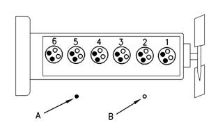
Illustration 33
Cylinder and valve loc ation
(A) Exhaust valves
(B) Inlet valves
g00935559
4.
Adjust the valve lash according to Table 13.
Use the following procedure to adjust the valve lash:
1. Put the No. 1 piston at the top center position
on the compress ion stroke. Refer to Systems
Operation, Testing and Adjusting, “Finding Top
Center Position for No. 1 Piston”.
a.
Lightly tap the rocker arm with a soft mallet.
This will ensure that the lifter roller seats
against the camshaft’s base circle.
Table 12
2. Adjust the valve lash according to Table 12.
a. Lightly tap the rocker arm with a soft mallet.
This will ensure that the lifter roller seats
agains t the camshaft’s base circle.
b. Loosen the adjustment locknut.
c. Place the appropriate feeler gauge between
5.
b. Loosen the adjustment locknut.
c. Plac e the appropriate feeler gauge between
rocker arm and the valve bridge. Then, turn
the adjustment screw in a cloc kwise direction.
Slide the feeler gauge between the rock er arm
and the valve bridge. Continue turning the
adjustment screw until a slight drag is felt on
the feeler gauge. Remove the feeler gauge.
d. Tighten the adjustment locknut to a torque
of 30 ± 7 N·m (22 ± 5 lb ft). Do not allow
the adjustment screw to turn while you are
tightening the adjustment locknut. Recheck
the valve lash after tightening the adjustment
locknut.
Remove the timing bolt from the flywheel after all
adjustments to the valve lash have been made.
Reinstall the timing cover.
rocker arm and the valve bridge. Then, turn
the adjustment screw in a clockwise direction.
Slide the feeler gauge between the rocker arm
and the valve bridge. Continue turning the
adjustment screw until a slight drag is felt on
the feeler gauge. Remove the feeler gauge.
d. Tighten the adjustment locknut to a torque
of 30 ± 7 N·m (22 ± 5 lb ft). Do not allow
the adjustment screw to turn while you are
tightening the adjustment locknut. Recheck
the valve lash after tightening the adjustment
locknut.
Refer to Systems Operation, Testing and Adjusting,
“Electronic Unit Injector - Adjust”.
This document has been printed from SPI². Not for Resale