 English
 Espaol
 Franais
 阿拉伯
阿拉伯 中文
中文 Deutsch
 Italiano
 Português
 日本
日本 韩国
韩国 български
 hrvatski
 esky
esky Dansk
Dansk Nederlands
 suomi
suomi Ελληνικ
 印度
印度 norsk
norsk Polski
 Roman
Roman русский
 Svenska
Perkins2506柴油发动机威尔逊P500E柴油发电机配件凸轮轴供应商,Perkins2506柴油发动机威尔逊P500E柴油发电机配件凸轮轴技术价格规格咨询服务,Perkins2506柴油发动机威尔逊P500E柴油发电机配件凸轮轴零配件供应,Perkins2506柴油发动机威尔逊P500E柴油发电机配件凸轮轴售后服务中心,Perkins2506柴油发动机威尔逊P500E柴油发电机配件凸轮轴,Perkins2506柴油发动机威尔逊P500E柴油发电机配件凸轮轴详细的技术参数,

产品中心
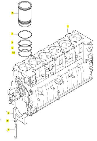
Perkins2506柴油发动机威尔逊P500E柴油发电机配件凸轮轴
详细描述
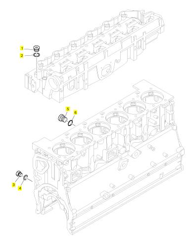
项目 零配件号码 新件号 描述
1 CH10287 1 CH10287 栓塞
2 T406205 1 T406205 密封O型圈
3 CH10285 1 CH10285 栓塞
4 T409314 1 T409314 密封O型圈
5 CH10287 1 CH10287 栓塞
6 CH10146 1 CH10146 密封O型圈
项目 零配件号码 新件号 描述
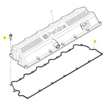
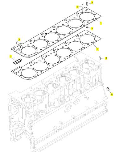
1 CH11512 1 CH11512 CYL 盖 ASSY 圈
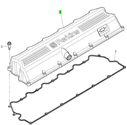
项目 零配件号码 新件号 描述
2 CH11353 1 CH11353 密封垫 - 摇臂室盖
3 CH10955 15 CH10955
项目 零配件号码 新件号 描述
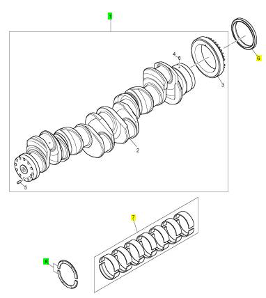
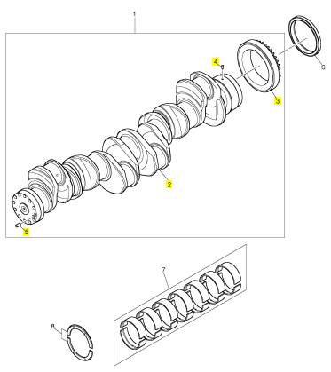
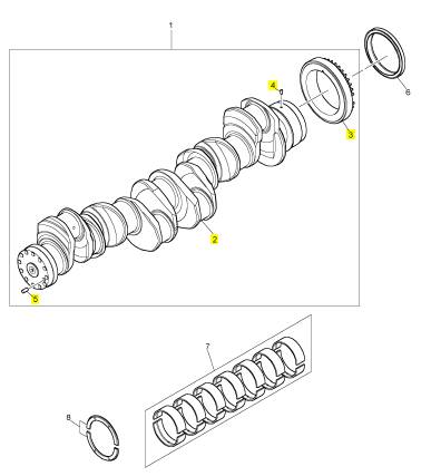
1 CH12792 1 CH12792 曲轴组合
1 CH11986 1 CH12792 曲轴组合
6 CH11379 1 CH11379 密封垫 -前油封
7 KRP3122 1 KRP3122 曲轴瓦
7 KRP3118 1 KRP3122 曲轴瓦
(7) KRP3116/025 1 KRP3116/025 曲轴瓦 -U/S
(7) KRP3116/050 1 KRP3116/050 曲轴瓦 -U/S
(7) KRP3117/025 1 KRP3117/025 曲轴瓦 -U/S
(7) KRP3117/050 1 KRP3117/050 曲轴瓦 -U/S
(7) CV11001 1 CV11001 要点壳轴承 (-)0.63 MM
(7) CV11002 1 CV11002 要点壳轴承 (-)0.127 MM
(7) CV11003 1 CV11003 要点壳轴承 (+)0.63 MM
(7) CV11004 1 CV11004 要点壳轴承 (+-)0.63 MM
8 KRP3206 1 KRP3206 止推片
项目 零配件号码 新件号 描述
2 1 曲轴
3 CH12793 1 CH12793 曲轴传动机构
4 CH10653 1 CH10653 合钉
5 CH10652 1 CH10652 销
项目 零配件号码 新件号 描述
2 1 曲轴
3 CH11687 1 CH12793 曲轴传动机构
4 CH10653 1 CH10653 合钉
5 CH10652 1 CH10652 销
项目 零配件号码 新件号 描述
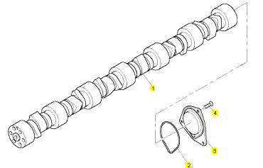
1 CH11988 1 CH11988 凸轮轴
2 CH10587 1 CH10587 密封O型圈
3 CH10588 1 CH10588 端盖
4 CH10589 3 CH10589 公制的螺旋
项目 零配件号码 新件号 描述
CH10221 5 CH10221 栓塞
CH10657 2 CH10657 密封O型圈
CH10658 2 CH10658 合钉
CH10663 1 CH10663 栓塞
CH10664 1 CH10664 栓塞
CH10667 1 CH10667 密封O型圈
1 CH10662 1 CH10662 间隔器
1 CH11398 1 CH11398 密封垫
2 1 密封垫
3 1 密封垫
4 CH10661 1 CH10661 合钉
5 CH10656 1 CH10656 合钉
6 CH10659 1 CH10659 合钉
7 CH10660 1 CH10660 密封O型圈
8 CH10658 2 CH10658 合钉
9 T400206 2 T400206 栓塞
9 CH10666 2 CH10666 栓塞
项目 零配件号码 新件号 描述
1 T400909 1 T400909 曲轴箱
1 CH12546 1 检查历史 曲轴箱
1 T400208 1 检查历史 曲轴箱
1 T400208 1 检查历史 曲轴箱
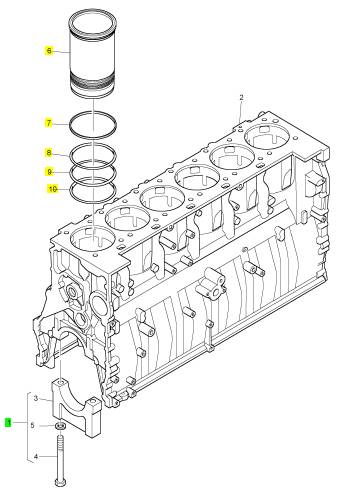
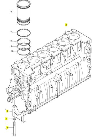
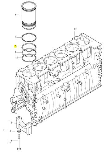
6 CH11180 6 CH11180 气缸衬套
7 CH10673 6 CH10673 带
8 CH10674 6 CH10674 密封垫 -油
9 CH10677 6 CH10677 密封垫 -油
10 CH11179 6 CH11179 密封垫 -油
项目 零配件号码 新件号 描述
2 1 缸体
3 1 轴承盖
4 T400209 14 T400209 螺拴
5 CH10672 14 CH10672 垫圈
项目 零配件号码 新件号 描述
8 CH10679 14 CH10679 螺拴
8 CH11180 6 CH11180 气缸衬套
项目 零配件号码 新件号 描述
2 1 缸体
3 CH11180 1 CH11180 气缸衬套
4 CH10673 6 CH10673 带
4 14 螺拴
5 CH10674 6 CH10674 密封垫 -油
6 CH10677 6 CH10677 密封垫 -油
7 CH11179 6 CH11179 密封垫 -油
8 7 轴承盖
9 T400209 14 T400209 螺拴
9 14 螺拴
10 CH10672 14 CH10672 垫圈
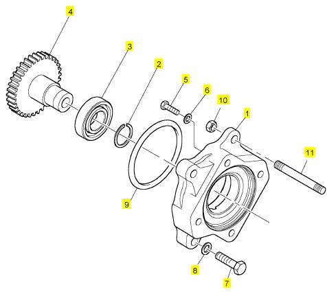
项目 零配件号码 新件号 描述
CH10567 1 CH10567 螺拴
1 CH10594 1 CH10594 承接器
2 CH10581 1 CH10581 扣环
3 CH10004 2 CH10004 滚珠轴承
4 CH10592 1 CH10592 燃料喷射泵传动机构
5 CH10583 3 CH10583 螺拴
5 CH10541 4 CH10255 垫圈
6 CH10593 3 CH10593 垫圈
7 CH10550 3 CH10550 螺拴
8 CH10255 4 CH10255 垫圈
9 CH10590 1 CH10590 密封O型圈
10 CH10798 1 CH10798 螺帽
11 CH12764 1 CH12764 图钉
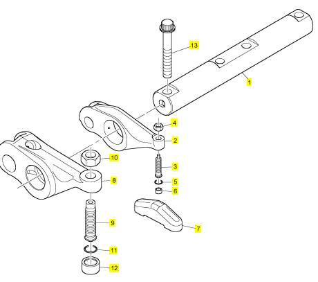
项目 零配件号码 新件号 描述
1 CH12695 3 CH12695 摇杆轴
1 CH10685 3 CH12695 摇杆轴
2 T400223 12 T400223 摇臂组合
2 CH11165 12 T400223 摇臂组合
3 CH12701 12 CH12701 螺旋
3 CH11162 12 检查历史 螺旋
3 CH11916 12 检查历史 螺旋
4 T400403 12 T400403 螺帽
4 CH10688 12 T400403 螺帽
4 CH12697 12 T400403 螺帽
5 CH10229 12 CH10229 密封O型圈
6 CH12702 12 CH12702 枢
6 CH10689 12 CH12702 钮扣
6 CH12510 12 CH12702 枢
7 CH12831 12 CH12831 结轴块
7 CH10680 12 CH12831 结轴
8 T400224 6 T400224 摇臂组合
8 CH11161 6 T400224 摇臂组合
8 CH12698 6 T400224 摇臂组合
9 CH11076 6 CH11076 螺旋
10 CH11077 6 CH11077 螺帽
11 CH11079 6 CH11079 密封O型圈
12 CH11078 6 CH11078 钮扣
13 CH10566 4 CH10566 螺拴
Lubricati on
System
Engine Oil Pressure - Test
i02571670
The engine oil pressure may be checked
electronically by using the electronic service tool.
The engine oil pressure can be measured with the
electronic service tool. Refer to Troubleshooting for
information on the use of the electronic serv ice tool.
Measuring Engine Oil Pressure
Work carefully around an engine that is running.
Engine parts that are hot, or parts that are moving,
can cause personal injury.
NOTICE
Keep all parts clean from contaminants.
Contaminants may cause rapid wear and shortened
component life.
NOTICE
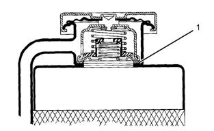
Illustration 34
Oil gallery plug
(1) Plug
g00977330
Care must be taken to ensure that fluids are contained
during performance of inspection, maintenance, test-
1.
Install Tool (A) into the oil gallery plugs (1).
ing, adjusting and repair of the product. Be prepared to
collect the fluid with suitable containers before open-
ing any compartment or disassembling any compo-
nent containing fluids.
Dispose of all fluids according to local regulations and
mandates.
Table 14
Tool (A) measures the oil pressure in the system.
Note: Engine oil pressure to the camshaft and main
bearings should be checked on each side of the
cylinder block at oil gallery plugs (1).
2. Start the engine. Refer to Operation and
Maintenance Manual, “Refill Capacities and
Rec ommendations” for the recommendations of
engine oil.
3. Rec ord the value of the engine oil pressure when
the engine is at operating temperature 100 °C
(212 °F).
The minimum engine oil pressure should be
approximately 275 to 414 kPa (40 to 59 psi).
4. Compare the recorded engine oil pressure with
the oil pressure indicators on the instrument panel
and the engine oil pressure that is displayed on
the electronic service tool.
5. An engine oil pressure indicator that has a defect
or an engine oil press ure sensor that has a defect
can give a false indication of a low oil pressure or
a high oil pressure. If there is a notable difference
between the engine oil pressure readings make
necessary repairs.
This document has been printed from SPI². Not for Resale
![]()
![]()
![]() 38
38
Testing and Adjusting Section
KENR6231
6.
7.
If low engine oil pressure is determined, refer to
“Reasons for Low Engine Oil Pressure”.
If high engine oil pressure is determined, refer to
“Reason for High Engine Oil Pressure”.
2.
Engine oil that is contaminated with fuel or coolant
will cause low engine oil pressure. High engine
oil level in the crankcase can be an indication
of contamination. Determine the reason for
contamination of the engine oil and make the
necessary repairs. Replace the engine oil with the
approved grade of engine oil. Refer to Operation
Reasons
Pressure
for
Low
Engine
Oil
and Maintenance Manual, “Engine Oil” for the
recommendations of engine oil.
|
|
|
|
Keep all parts clean from contaminants.
Contaminants may cause rapid wear and shortened
component life.
NOTICE
Care must be taken to ensure that fluids are contained
during performance of inspection, maintenance, test-
ing, adjusting and repair of the product. Be prepared to
collect the fluid with suitable containers before open-
ing any compartment or disassembling any compo-
nent containing fluids.
Dispose of all fluids acc ording to local regulations and
mandates.
• Engine oil level is low. Refer to Step 1.
• Engine oil is contaminated. Refer to Step 2.
Step 3.
Step 4.
screen. Refer to Step 5.
• The engine oil pump is faulty. Refer to Step 6.
to Step 7.
1. Check the engine oil level in the crankcase. The
oil level can possibly be too far below the oil pump
supply tube. This will cause the oil pump not to
have the ability to supply enough lubrication to the
engine components. If the engine oil level is low
add engine oil in order to obtain the correct engine
oil level. Refer to Operation and Maintenance
Manual, “Engine Oil” for the recommendations of
engine oil.
NOTICE
Perkins oil filters are manufactured to Perkins speci-
fications. Use of an oil filter that is not recommended
by Perkins c ould result in severe damage to the en-
gine bearings, crankshaft, etc., as a result of the larger
waste particles from unfiltered oil entering the engine
lubricating system. Only use oil filters recommended
by Perkins.
3. If the engine oil bypass valves are held in the
open position, a reduc tion in the oil pressure can
be the result. This may be due to debris in the
engine oil. If the engine oil bypass valves are
stuck in the open position, remove each engine
oil by pass valve and clean each bypass valve
in order to correct this problem. You must also
clean each bypass valve bore. Install new engine
oil filters. New engine oil filters will prevent more
debris from causing this problem. For information
on the repair of the engine oil bypass valves, refer
to Disassembly and Assembly, “Engine Oil Filter
Base - Disassemble”.
4. An oil line or an oil passage that is open, broken,
or disconnected will cause low engine oil pressure.
An open lubrication system could be caused by
a piston cooling jet that is missing or damaged.
Determine the reason for an open lubrication
system of the engine and make the necessary
repairs.
Note: The piston cooling jets direct engine oil toward
the bottom of the piston in order to cool the piston.
This also provides lubrication for the piston pin.
Breakage, a restriction or incorrect installation of the
piston cooling jets will cause seizure of the piston.
5. The inlet screen of the oil pickup tube for the
engine oil pump can have a restriction. This
restriction will cause cavitation and a loss of
engine oil pres sure. Check the inlet screen on
the oil pickup tube and remove any material that
may be restricting engine oil flow. Low engine oil
pressure may also be the result of the oil pickup
tube that is drawing in air. Check the joints of the
oil pickup tube for cracks or a damaged O-ring
seal. Remove the engine oil pan in order to gain
access to the oil pickup tube and the oil screen.
Refer to Disassembly and Assembly, “Engine Oil
Pan - Remove and Install” for more information.
This document has been printed from SPI². Not for Resale
![]()
![]()
![]()
![]() KENR6231
KENR6231
39
Testing and Adjusting Section
6.
7.
Check the following problems that may occur to
the engine oil pump.
a. Air leakage in the supply side of the oil pump
will also cause cavitation and loss of oil
pressure. Check the supply side of the oil pump
and make necessary repairs. For information
on the repair of the engine oil pump, refer to
Disassembly and Assembly, “Engine Oil Pump
- Remove”.
b. Oil pump gears that have too much wear will
cause a reduction in oil pressure. Repair the
engine oil pump. For information on the repair
of the engine oil pump, refer to Disassembly
and Assembly, “Engine Oil Pump - Remove”.
Excessive clearance at engine bearings will
cause low engine oil pressure. Check the
engine components that have excessive bearing
clearance and make the necessary repairs.
NOTICE
Perkins oil filters are manufactured to Perkins speci-
fications. Use of an oil filter that is not recommended
by Perkins c ould result in severe damage to the en-
gine bearings, crankshaft, etc., as a result of the larger
waste particles from unfiltered oil entering the engine
lubricating system. Only use oil filters recommended
by Perkins.
i02553373
Excessive Bearing Wear -
Inspect
When some components of the engine show bearing
wear in a short time, the cause can be a restriction in
an oil passage.
Reason
for High
Engine
Oil
An engine oil pressure indicator may show that there
is enough oil pressure, but a component is worn
Pressure
NOTICE
due to a lack of lubrication. In such a case, look at
the passage for the oil supply to the component.
A restriction in an oil supply passage will not allow
Keep all parts clean from contaminants.
Contaminants may cause rapid wear and shortened
component life.
NOTICE
Care must be taken to ensure that fluids are contained
during performance of inspection, maintenance, test-
ing, adjusting and repair of the product. Be prepared to
collect the fluid with suitable containers before open-
ing any compartment or disassembling any compo-
nent containing fluids.
Dispose of all fluids according to local regulations and
mandates.
Engine oil pressure will be high if the engine oil
bypass valves become stuck in the closed position
and the engine oil flow is restricted. Foreign matter
in the engine oil system could be the cause for the
restriction of the oil flow and the movement of the
engine oil bypass valves. If the engine oil bypass
valves are stuck in the closed position, remove
each bypass valve and clean each bypass valve in
order to correct this problem. You must also clean
each bypass valve bore. Install new engine oil
filters. New engine oil filters will prevent more debris
from causing this problem. For information on the
repair of the engine oil filter bypass valve, refer to
Disassembly and Assembly, “Engine Oil Filter Base -
Disassemble”.
enough lubrication to reach a component. This will
result in early wear.
i02553374
Excessive Engine Oil
Consumption - Inspect
Engine Oil Leaks on the Outside of
the Engine
Check for leakage at the seals at each end of the
crankshaft. Look for leak age at the gasket for the
engine oil pan and all lubrication system connections.
Look for any engine oil that may be leaking from
the crankcase breather. This can be caused by
combus tion gas leakage around the pistons. A dirty
crankcase breather will cause high pressure in the
crankcase. A dirty crankcase breather will cause the
gaskets and the seals to leak.
Engine Oil Leaks into the
Combustion Area of the Cylinders
Engine oil that is leaking into the combustion area of
the cylinders can be the cause of blue s moke. There
are several possible way s for engine oil to leak into
the combustion area of the c ylinders:
• Leaks between worn valve guides and valve stems
This document has been printed from SPI². Not for Resale
![]() 40
40
Testing and Adjusting Section
KENR6231
•
•
•
•
•
Worn components or damaged components
(pistons, piston rings, or dirty return holes for the
engine oil)
Incorrect installation of the compression ring and/or
the intermediate ring
Leaks past the seal rings in the turbocharger shaft
Overfilling of the crankcase
Wrong dipstick or guide tube
Excessive consumption of engine oil can also
result if engine oil with the wrong viscosity is used.
Engine oil with a thin viscosity can be caused by fuel
leakage into the crankcase or by increased engine
temperature.
Increased
Engine
Oil
i02553375
Temperature
- Inspect
If the oil temperature is high, then check for a
restriction in the oil pas sages of the oil cooler. A
restriction in the oil cooler will not cause low oil
pressure in the engine.
Determine if the oil cooler bypass valve is held in the
open position. This condition will allow the oil to pass
through the v alve instead of the oil cooler. The oil
temperature will increase.
Refer to Operation and Maintenance Manual, “Refill
Capacities” for the correct lubricating oil.
This document has been printed from SPI². Not for Resale
![]()
![]() KENR6231
KENR6231
41
Testing and Adjusting Section
Cooling
System
i02553376
5.
Check the sending unit. In some conditions, the
temperature sensor in the engine sends signals
to a sending unit. The sending unit converts these
signals to an electrical impulse which is used by a
mounted gauge. If the sending unit malfunctions,
Cooling
System - Check
the gauge can show an incorrect reading. Also if
the electric wire breaks or if the electric wire shorts
(Overheating)
Above normal coolant temperatures can be caused
by many conditions. Use the following procedure
to determine the cause of above normal coolant
temperatures:
Personal injury can result from escaping fluid un-
der pressure.
If a pressure indication is shown on the indicator,
push the release valve in order to relieve pressure
before removing any hose from the radiator.
1. Check the coolant level in the cooling system.
Refer to Operation and Maintenance Manual,
“Cooling System Coolant Level - Check”. If the
coolant level is too low, air will get into the cooling
system. Air in the cooling system will cause a
reduction in coolant flow and bubbles in the
coolant. Air bubbles will keep coolant away from
the engine parts, which will prevent the transfer of
heat to the coolant. Low coolant level is caused by
leaks or incorrectly filling the radiator.
2. Check the mixture of antifreeze and water. Refer
to Operation and Maintenance Manual, “Fluid
Recommendations”. If the coolant mixture is
incorrect, drain the s ystem. Put the correct mixture
of water, antifreeze and coolant conditioner in the
cooling system.
3. Check for air in the cooling system. Air can enter
the cooling system in different ways. The most
common causes of air in the cooling system
are not filling the cooling system correctly and
combustion gas leakage into the cooling system.
Combustion gas can get into the system through
ins ide cracks, a damaged cylinder head, or a
damaged cylinder head gasket. Air in the c ooling
system c auses a reduction in coolant flow and
bubbles in the coolant. Air bubbles keep coolant
away from the engine parts, which prevents the
transfer of heat to the coolant.
4. Check the water temperature gauge. A water
temperature gauge which does not work correctly
will not show the correct temperature. Refer
to Systems Operation, Testing and Adjusting,
“Cooling System - Inspect”.
6.
7.
8.
9.
out, the gauge can show an incorrect reading.
Check the radiator.
a. Check the radiator for a restriction to coolant
flow. Check the radiator for debris, dirt, or
deposits on the inside of the radiator core.
Debris, dirt, or deposits will restrict the flow of
coolant through the radiator.
b. Check for debris or damage between the fins
of the radiator core. Debris between the fins
of the radiator core restricts air flow through
the radiator core. Refer to Systems Operation,
Testing and Adjusting, “Cooling System -
Inspect”.
c. Ensure that the radiator size is adequate for
the application. An undersized radiator does
not have enough area for the effective release
of heat. This may cause the engine to run
at a temperature that is higher than normal.
The normal temperature is dependent on the
ambient temperature.
Check the filler c ap. A pressure drop in the
radiator can cause the boiling point to be lower.
This can cause the cooling system to boil. Refer
to Systems Operation, Testing and Adjusting,
“Cooling System - Tes t”.
Check the fan and/or the fan shroud.
a. The fan must be large enough to send air
through most of the area of the radiator core.
Ensure that the size of the fan and the position
of the fan are adequate for the application.
b. The fan shroud must be the proper size and
the fan shroud must be positioned correctly.
Ensure that the size of the fan shroud and the
position of the fan shroud are adequate for the
application.
If the fan is belt driven, check for loose drive belts .
A loose fan drive belt will cause a reduction in the
air flow across the radiator. Check the fan drive
belt for proper belt tension. Adjust the tension of
the fan drive belt, if necessary. Refer to Sys tems
Operation, Testing and Adjusting, “Belt Tension
Chart”.
This document has been printed from SPI². Not for Resale
![]()
![]() 42
42
Testing and Adjusting Section
KENR6231
10. Check the coolin, g system hoses and clamps.
Damaged hoses with leaks can normally be seen.
Hoses that have no visual leak s can soften during
operation. The soft areas of the hose can become
kinked or crushed during operation. These areas
of the hose can cause a restriction in the coolant
flow. Hoses become soft and/or get cracks
after a period of time. The inside of a hose can
deteriorate, and the loose particles of the hose
can cause a restriction of the coolant flow. Refer
to Operation and Maintenance Manual, “Hoses
and Clamps - Inspect/Replace”.
11. Check for a restriction in the air inlet system.
A restriction of the air that is coming into the
engine can cause high cylinder temperatures.
High cy linder temperatures cause higher than
normal temperatures in the cooling system. Refer
to Systems Operation, Testing and Adjusting, “Air
Inlet and Exhaust System - Inspect”.
a. If the measured restriction is higher than the
maximum permissible restriction, remove the
foreign material from the engine air cleaner
element or install a new engine air cleaner
element. Refer to Operation and Maintenance
Manual, “Engine Air Cleaner Element -
Clean/Replace”.
b. Check for a restriction in the air inlet system
again.
c. If the measured restriction is still higher than
the maximum permissible restriction, check the
air inlet piping for a restriction.
12. Check for a restriction in the exhaust system.
A restriction of the air that is coming out of the
engine can cause high cylinder temperatures.
a. Make a visual inspection of the exhaust system.
Check for damage to exhaust piping or for a
damaged muffler. If no damage is found, check
the exhaust system for a restriction. Refer to
Systems Operation, Testing and Adjusting, “Air
Inlet and Exhaust System - Inspect”.
b. If the measured restriction is higher than the
maximum permissible restriction, there is a
restriction in the exhaust system. Repair the
exhaust system, as required.
13. Check the shunt line, if the shunt system is
used. The shunt line must be submerged in the
expansion tank. A restriction of the shunt line
from the radiator top tank to the engine water
pump inlet will cause a reduction in water pump
efficiency. A reduction in water pump efficiency
will result in low coolant flow and overheating.
14. Chec k the water temperature regulator. A water
temperature regulator that does not open, or
a water temperature regulator that only opens
part of the way can cause overheating. Refer to
Systems Operation, Testing and Adjusting, “Water
Temperature Regulator - Test”.
15. Check the water pump. A water pump with a
damaged impeller does not pump enough coolant
for correct engine cooling. Remove the water
pump and check for damage to the impeller. Refer
to Systems Operation, Testing and Adjusting,
“Water Pump - Test”.
16. Chec k the air flow through the engine
compartment. The air flow through the radiator
comes out of the engine compartment. Ensure
that the filters, air conditioner, and similar items
are not installed in a way that prevents the free
flow of air through the engine compartment.
17. Chec k the aftercooler. A restriction of air flow
through the air to air aftercooler (if equipped) can
cause overheating. Check for debris or deposits
which would prevent the free flow of air through
the aftercooler.
18. Cons ider high outside temperatures. When
outside temperatures are too high for the rating
of the cooling system, there is not enough of a
temperature difference between the outside air
and coolant temperatures.
19. Cons ider high altitude operation. The cooling
capacity of the cooling system goes down as
the engine is operated at higher altitudes. A
pressurized cooling s ystem that is large enough to
keep the coolant from boiling must be used.
i02553378
Cooling System - Inspect
Cooling systems that are not regularly inspected are
the cause for increased engine temperatures. Make
a visual inspection of the cooling system before any
tests are performed.
Personal injury can result from escaping fluid un-
der pressure.
If a pressure indication is shown on the indicator,
push the release valve in order to relieve pressure
before removing any hose from the radiator.
This document has been printed from SPI². Not for Resale
![]()
![]()
![]()
![]() KENR6231
KENR6231
43
Testing and Adjusting Section
1.
2.
Check the coolant level in the cooling system.
Refer to Operation and Maintenance Manual,
“Cooling System Coolant Level - Check”.
Check the quality of the coolant. The coolant
should have the following properties:
• Color that is similar to new coolant
• Odor that is similar to new coolant
• Free from dirt and debris
If the coolant does not have these properties,
drain the sy stem and flush the system. Refill
the cooling system with the correct mixture of
water, antifreeze, and coolant conditioner. Refer
to Operation and Maintenance Manual, “Fluid
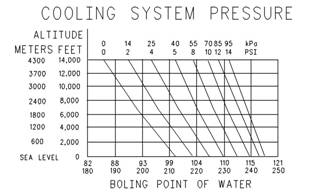
Illustration 35
Boiling point of water
g00921815
3.
Recommendations”.
Look for leak s in the system.
Remember that temperature and pressure work
together. When a diagnosis is made of a cooling
system problem, temperature and pressure must be
checked. Cooling system pressure will have an effec t
on the cooling system temperature. For an example,
Note: A small amount of coolant leak age across
the surfac e of the water pump seals is normal. This
leakage is required in order to provide lubrication for
this type of seal. A hole is provided in the water pump
housing in order to allow this coolant/seal lubric ant
to drain from the pump housing. Intermittent leakage
of small amounts of coolant from this hole is not an
indication of water pump seal failure.
4. Ensure that the air flow through the radiator does
not have a restriction. Look for bent core fins
between the folded cores of the radiator. Also, look
for debris between the folded cores of the radiator.
5. Inspect the drive belts for the fan.
6. Check for damage to the fan blades.
7. Look for air or combustion gas in the cooling
system.
8. Inspect the filler cap, and check the surface that
seals the filler cap. This surface must be clean.
i02553379
Cooling System - Test
This engine has a pres sure type cooling system. A
pressure type cooling system has two advantages.
The cooling system can be operated in a safe manner
at a temperature higher than the normal boiling point
(steam) of water.
This type of system prevents cavitation in the water
pump. Cavitation is the forming of low pressure
bubbles in liquids that are caused by mechanical
forces. It is difficult to create a pocket of air in this
type of cooling system.
refer to Illustration 35. This will show the effect of
pressure on the boiling point (steam) of water. This
will also show the effect of height above s ea level.
Personal injury can result from hot coolant, steam
and alkali.
At operating temperature, engine coolant is hot
and under pressure. The radiator and all lines
to heaters or the engine contain hot coolant or
steam. Any contact can cause severe burns.
Remove filler cap slowly to relieve pressure only
when engine is stopped and radiator cap is cool
enough to touch with your bare hand.
Cooling System Conditioner contains alkali. Avoid
contact with skin and eyes.
The coolant level must be to the correct level in order
to check the coolant sys tem. The engine must be
cold and the engine must not be running.
After the engine is cool, loosen the pressure cap
in order to relieve the pressure out of the cooling
sys tem. Then remove the pressure c ap.
The level of the coolant should not be more than
13 mm (0.5 inch) from the bottom of the filler pipe. If
the cooling system is equipped with a sight glass,
the coolant should be to the proper level in the sight
glass.
This document has been printed from SPI². Not for Resale
![]()
![]()
| |||||||||||||
| |||||||||||||
Testing and Adjusting Section
KENR6231
Checking the Filler Cap
Table 15
•
•
Seal
Surface for seal
One cause for a pressure loss in the cooling system
can be a damaged seal on the radiator filler cap.
2.
3.
4.
5.
Remove any deposits that are found on these
items, and remove any material that is found on
these items.
Install the filler cap onto Tooling (A).
Look at the gauge for the exact pressure that
opens the filler cap.
Compare the gauge reading with the opening
pressure that is listed on the filler cap.
If the filler cap is damaged, replace the filler c ap.
Testing The Radiator And Cooling
System For Leaks
Table 16
Illustration 36
Typical schematic of filler cap
(1) Sealing surface of both filler cap and radiator
g01096114
Use the following procedure in order to check the
cooling system for leaks:
Personal injury can result from hot coolant, steam
and alkali.
At operating temperature, engine coolant is hot
and under pressure. The radiator and all lines
to heaters or the engine contain hot coolant or
steam. Any contact can cause severe burns.
Remove filler cap slowly to relieve pressure only
when engine is stopped and radiator cap is cool
enough to touch with your bare hand.
Cooling System Conditioner contains alkali. Avoid
contact with skin and eyes.
To check for the amount of pressure that opens the
filler cap, use the following procedure:
1. After the engine cools, carefully loosen the filler
cap. Slowly release the pressure from the cooling
system. Then, remove the filler cap.
Carefully inspect the filler cap. Look for any
damage to the seals and to the sealing surface.
Inspect the following components for any foreign
substances:
• Filler cap
Personal injury can result from hot coolant, steam
and alkali.
At operating temperature, engine coolant is hot
and under pressure. The radiator and all lines
to heaters or the engine contain hot coolant or
steam. Any contact can cause severe burns.
Remove filler cap slowly to relieve pressure only
when engine is stopped and radiator cap is cool
enough to touch with your bare hand.
Cooling System Conditioner contains alkali. Avoid
contact with skin and eyes.
1. After the engine is cool, loosen the filler cap slowly
and allow pressure out of the cooling system.
Then remove the filler cap from the radiator.
2. Ensure that the coolant level is above the top of
the radiator core.
3. Install Tooling (A) onto the radiator.
4. Take the pressure reading on the gauge to 20 kPa
(3 psi) more than the pressure on the filler cap.
This document has been printed from SPI². Not for Resale
![]()
![]()
![]()
| |||||||||||||
45
Testing and Adjusting Section
5.
6.
Check the radiator for leakage on the outside.
Check all connection points for leakage, and
check the hoses for leakage.
Coolant temperature can also be read on the display
screens of the Electronic Service Tool.
The cooling system does not have leakage only if the
following conditions exist:.
• You do not observe any outside leakage.
• The reading remains steady after five minutes.
The inside of the cooling system has leakage only if
the following conditions exist:
• The reading on the gauge goes down.
• You do NOT observe any outside leakage.
Make any repairs, as required.
Test For The Water Temperature
Gauge
Table 17
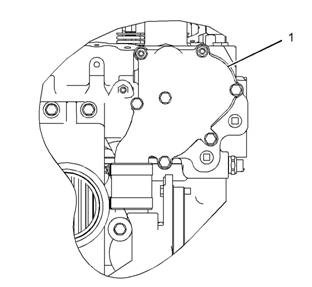
Illustration 37
Typical example
(1) Water manifold assembly
g01096115
Personal injury can result from escaping fluid un-
der pressure.
If a pressure indication is shown on the indicator,
push the release valve in order to relieve pressure
before removing any hose from the radiator.
Remove a plug from water manifold assembly (1).
Install Tooling (A) in the open port:
A temperature indicator of known accuracy can also
be used to make this check.
Start the engine. Run the engine until the temperature
reaches the desired range according to the test
thermometer. If necessary, place a cover over part of
the radiator in order to cause a restriction of the air
flow. The reading on the water temperature indicator
should agree with the test thermometer within the
tolerance range of the water temperature indicator.
Making contact with a running engine can cause
burns from hot parts and can cause injury from
rotating parts.
When working on an engine that is running, avoid
contact with hot parts and rotating parts.
Check the accuracy of the water temperature
Water Temperature
- Test
i02553380
Regulator
indicator or water temperature sensor if you find
either of the following conditions:
• The engine runs at a temperature that is too hot,
but a normal temperature is indicated. A loss of
coolant is found.
• The engine runs at a normal temperature, but a
hot temperature is indicated. No loss of coolant
is found.
Personal injury can result from escaping fluid un-
der pressure.
If a pressure indication is shown on the indicator,
push the release valve in order to relieve pressure
before removing any hose from the radiator.
1. Remove the water temperature regulator from the
engine.
This document has been printed from SPI². Not for Resale
![]()
![]() 46
46
Testing and Adjusting Section
KENR6231
2.
3.
4.
5.
Heat water in a suitable container until the
temperature is 98 °C (208 °F).
Hang the water temperature regulator in the
container of water. The water temperature
regulator must be below the surface of the water
and away from the sides and the bottom of the
container.
Keep the water at the correct temperature for ten
minutes.
After ten minutes, remove the water temperature
regulator. Ensure that the water temperature
regulator is open.
Replace the water temperature regulator if the
water temperature regulator is not open at the
specified temperature. Refer to Specifications,
“Water Temperature Regulator”.
i02553381
Making contact with a running engine can cause
burns from hot parts and can cause injury from
rotating parts.
When working on an engine that is running, avoid
contact with hot parts and rotating parts.
Perform the following procedure in order to determine
if the water pump is operating correctly:
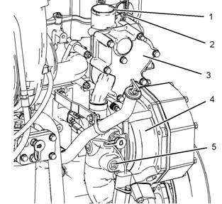
1. Remove the plug from port (2).
2. Install Tooling (A) in port (2).
3. Start the engine. Run the engine until the coolant
is at operating temperature.
4. Note the water pump pres sure. The water pump
pressure should be 100 to 125 kPa (15 to 18 psi).
Water Pump -
Test
Table 18
Tool
A
Required Tools
Part Number Part Description
GE50033 Pressure Gauge
Qty
1
Illustration 38
Typical example
(1) Water outlet
(2) Port
(3) Temperature regulator hous ing
(4) Water pump
(5) Port
g01033819
This document has been printed from SPI². Not for Resale
![]() KENR6231
KENR6231
47
Testing and Adjusting Section
Basic
Engine
i02553382
Connecting rod bearings are available with s maller
inside diameters than the original size bearings.
These bearings are for crankshafts that have been
ground.
Piston
Ring Groove - Inspect
If necessary, replace the connecting rod bearings.
Refer to Disassembly and Assembly, “Connecting
Rod Bearings - Remove” and Disassembly and
Assembly, “Connecting Rod Bearings - Install” for the
correct procedure.
Inspect the Piston and the Piston
Rings
1. Check the piston for wear and other damage.
2. Check that the piston rings are free to move in the
grooves and that the rings are not broken.
Main
Bearings
- Inspect
i02553396
Inspect the Clearance of the Piston
Ring
1. Remove the piston rings and clean the grooves
and the piston rings.
2. Fit new piston rings in the piston grooves.
3. Check the clearance for the piston ring by placing
a suitable feeler gauge between the piston groove
and the top of piston ring. Refer to Specifications,
“Piston and Rings” for the dimensions.
Inspect the Piston Ring End Gap
1. Clean all carbon from the top of the cylinder bores .
2. Place each piston ring in the cylinder bore just
below the cylinder ring ridge.
3. Use a suitable feeler gauge to measure piston
ring end gap. Refer to Specifications, “Piston and
Rings” for the dimensions.
Note: The coil spring must be removed from the oil
control ring before the gap of the oil control ring is
measured.
i02553391
Connecting Rod Bearings -
Inspect
Main bearings are available with smaller inside
diameters than the original size bearings. These
bearings are for crankshafts that have been ground.
If nec essary, replace the main bearings. Refer
to Disassembly and Assembly, “Crankshaft Main
Bearings - Remove and Install” for the correct
procedure.
i02571419
Cylinder Block - Inspect
1. Clean all of the coolant passages and the oil
passages.
2. Check the cylinder block for cracks and damage.
3. The top deck of the cylinder block must not be
machined. This will affect the depth of the cylinder
liner flange and the piston height above the
cylinder block.
4. Check the front cams haft bearing for wear. Refer
to Specifications, “Camshaft Bearings” for the
correct specification of the camshaft bearing. If a
new bearing is needed, use a suitable adapter to
press the bearing out of the bore. Ensure that the
oil hole in the new bearing faces the front of the
block. The oil hole in the bearing must be aligned
with the oil hole in the cylinder block. The bearing
must be aligned with the face of the recess.
The connecting rod bearings fit tightly in the bore in
the rod. If the bearing joints are worn, check the bore
size. This can be an indication of wear because of
a loose fit.
This document has been printed from SPI². Not for Resale
![]()
![]() 48
48
Testing and Adjusting Section
KENR6231
Cylinder
Inspect
Liner
Projection
i02553404
-
Table 19
|
Required Tools | |||
|
Tool |
Part Number |
Part Description |
Qty |
|
A |
GE50005 |
Clamp bolt |
6 |
|
B |
GE50006 |
Clamp washer |
6 |
|
C |
GE50007 |
Fibre washer |
6 |
|
D |
GE50002 |
Cylinder liner projection tool |
1 |
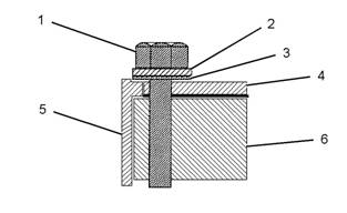
Note: The projection of the cylinder liner is measured
from the top of the cy linder liner to the top of the
spacer plate.
Illustration 39
Liner Projection Components
(1) Bolt
(2) Washer
(3) Washer
(4) Spacer plate
(5) Cylinder liner
(6) Block
g01096458
This document has been printed from SPI². Not for Resale
![]() KENR6231
KENR6231
49
Testing and Adjusting Section
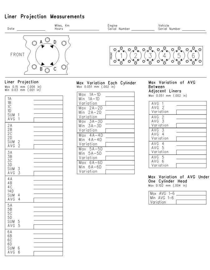
Illustration 40
g00443044
This document has been printed from SPI². Not for Resale
![]() 50
50
Testing and Adjusting Section
KENR6231
1.
2.
3.
4.
5.
6.
7.
8.
9.
Ensure that the top face of the cylinder block (6)
is clean. Install a new s pacer plate gasket and a
clean spacer plate.
Install the cylinder liners to the cylinder block
without seals or bands. Ensure that the cylinder
liners are installed to the original positions.
Install Tooling (B) and Tooling (C) to Tooling (A).
Refer to illustration 39.
Install Tooling (A) around the liner. Refer to
illustration 39.
Tighten the bolts (6) to a torque of 95 N·m (70 lb ft).
Use Tooling (D) to measure the cylinder liner
projection at "A", "B", "C" and "D". Refer to
illustration 40.
Record the measurements for the cylinder.
Repeat steps 3 to 7 for each cylinder.
Add the four readings for each cylinder. Divide the
sum by four in order to find the average.
Do not exceed the maximum liner projection of
0.152 mm (0.006 inch). The excessive liner projection
will contribute to cracking of the liner flange.
When the liner projection is correct, put a temporary
mark on the liner and the spacer plate. Set the liners
aside.
Note: Refer to Disassembly and Assembly, “Cy linder
Liner - Install” for the correct final installation
procedure for the cylinder liners.
i02553516
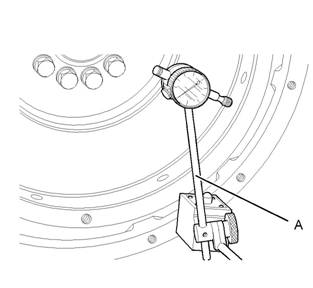
Flywheel - Inspect
Face Runout (Axial Eccentricity) of
the Flywheel
Table 21
Required Tools
Tool Part Number Part Description Qty
A 21825617 Dial Indicator Group 1
Table 20
|
Specifications | |
|
Liner Projection |
0.025 to 0.152 mm (0.0010 to 0.0060 inch) |
|
Maximum Variation In Each Liner |
0.051 mm (0.0020 inch) |
|
Maximum Average Variation Between Adjacent Liners |
0.051 mm (0.0020 inch) |
|
Maximum Variation Between All Liners |
0.102 mm (0.0040 inch) |
Note: If the liner projection changes around the liner,
turn the liner to a new position within the bore. If the
liner projection is not within specifications, move the
liner to a different bore. Inspect the top face of the
cylinder block.
If the cylinder liner projections are below 0.025 mm
(0.0010 inch) or 0.051 mm (0.0020 inch) corrective
action must be taken. A thinner spacer plate may
be used. The thinner spacer plate is available from
your Perkins distributor. The plates are 0.076 mm
(0.0030 inch) thinner than the original plate. The
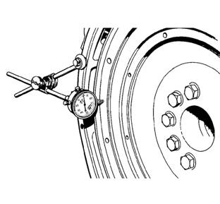
Illustration 41
Checking face runout of the flywheel
g00286049
plates will increase the liner projection. Us e these
spacer plates to compensate for low liner projections
which are less than the 0.076 mm (0.0030 inch). Use
these spacer plates if inspection of the top face of
the cylinder block reveals no measurable damage
directly under the liner flanges but the average liner
projection is less than 0.076 mm (0.0030 inch).
1.
2.
Install Tooling (A). Refer to illustration 41. Always
put a force on the crankshaft in the same direction
before the dial indicator is read. This will remove
any crankshaft end clearanc e.
Set the dial indicator to read 0.0 mm (0.00 inch).
This document has been printed from SPI². Not for Resale
![]()
![]()
![]()
![]() KENR6231
KENR6231
51
Testing and Adjusting Section
3.
4.
Turn the flywheel at intervals of 45 degrees and
read the dial indicator.
Take the measurements at all four points. The
difference between the lower measurements and
the higher measurements that are performed at
all four points must not be more than 0.15 mm
(0.006 inch), which is the maximum permissible
face runout (axial eccentricity) of the flywheel.
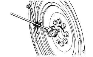
Bore
Runout (Radial Eccentricity)
of the Flywheel
Table 22
Required Tools
Tool Part Number Part Description
Qty
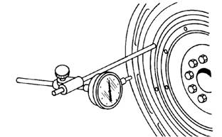
Illustration 43
Flywheel clutch pilot bearing bore
g00286058
A
21825617
Dial Indicator Group
1
5.
6.
To find the runout (ec centricity) of the pilot bearing
bore, use the preceding procedure.
The runout (eccentricity) of the bore for the pilot
bearing in the flywheel must not exceed 0.13 mm
(0.005 inch).
i02553531
Flywheel Housing - Inspect
Table 23
|
Required Tools | |||
|
Tool |
Part Number |
Part Description |
Qty |
|
A |
21825617 |
Dial Indicator Group |
1 |
Illustration 42
Checking bore runout of the flywheel
1. Install Tooling (A). Refer to illustration 42.
g01278054
Face Runout (Axial Eccentricity) of
the Flywheel Housing
2.
3.
4.
Set the dial indicator to read 0.0 mm (0.00 inch).
Turn the flywheel at intervals of 45 degrees and
read the dial indicator.
Take the measurements at all four points. The
difference between the lower measurements and
the higher measurements that are performed at
all four points must not be more than 0.15 mm
(0.006 inch) for the maximum permissible face
runout (radial eccentricity) of the flywheel.
Illustration 44
Typical example
g00285931
If you us e any other method except the method that
is given here, always remember that the bearing
clearance must be removed in order to receive the
correct measurements.
This document has been printed from SPI². Not for Resale

![]()
![]()
![]()
![]()
![]() 52
52
Testing and Adjusting Section
KENR6231
1.
2.
Install Tooling (A) to the fly wheel so the anvil of the
dial indicator will contact the face of the flywheel
housing. Refer to illus tration 44.
Use a rubber mallet and tap the crankshaft toward
the rear before the dial indicator is read at each
point.
Illustration 47
Checking bore runout of the flywheel housing
g00285932
Illustration 45
Checking face runout of the flywheel housing
g00285932
3.
4.
Turn the flywheel while the dial indicator is set at
0.0 mm (0.00 inch) at location (A). Read the dial
indicator at locations (B), (C) and (D).
The difference between the lower measurements
and the higher measurements that are performed
at all four points must not be more than 0.38 mm
(0.015 inch), which is the maximum permissible
face runout (axial eccentricity) of the flywheel
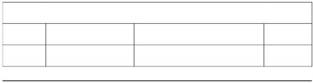
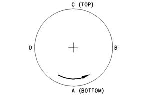
Illustration 48
g00763974
housing.
Bore Runout (Radial Eccentricity)
of the Flywheel Housing
2.
While the dial indicator is in the position at location
(C) adjust the dial indicator to 0.0 mm (0.00 inch).
Push the crankshaft upward against the top of
the bearing. Refer to Illustration 48. Write the
measurement for bearing clearance on line 1 in
column (C).
Illustration 46
Typical example
g00285934
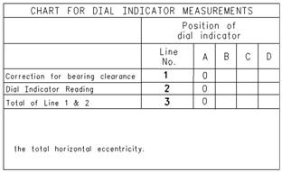
Note: Write the measurements for the dial indicator
with the correct notations. This notation is necessary
for making the calc ulations in the chart correctly.
3. Divide the measurement from Step 2 by two. Write
this number on line 1 in columns (B) and (D).
4. Turn the flywheel in order to put the dial indicator
at position (A). Adjust the dial indicator to 0.0 mm
(0.00 inch).
5. Turn the flywheel counterclockwise in order to
put the dial indicator at position (B). Write the
measurements in the chart.
6. Turn the flywheel counterclockwise in order to
put the dial indicator at position (C). Write the
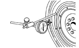
1.
Install Tooling (A) to the fly wheel so the anvil of the
dial indicator will contact the bore of the flywheel
housing. Refer to illus tration 46.
measurement in the chart.
This document has been printed from SPI². Not for Resale