 English
 Espaol
 Franais
 阿拉伯
阿拉伯 中文
中文 Deutsch
 Italiano
 Português
 日本
日本 韩国
韩国 български
 hrvatski
 esky
esky Dansk
Dansk Nederlands
 suomi
suomi Ελληνικ
 印度
印度 norsk
norsk Polski
 Roman
Roman русский
 Svenska
Perkins2306柴油发动机威尔逊P550柴油发电机配件传感器供应商,Perkins2306柴油发动机威尔逊P550柴油发电机配件传感器技术价格规格咨询服务,Perkins2306柴油发动机威尔逊P550柴油发电机配件传感器零配件供应,Perkins2306柴油发动机威尔逊P550柴油发电机配件传感器售后服务中心,Perkins2306柴油发动机威尔逊P550柴油发电机配件传感器,Perkins2306柴油发动机威尔逊P550柴油发电机配件传感器详细的技术参数,

产品中心
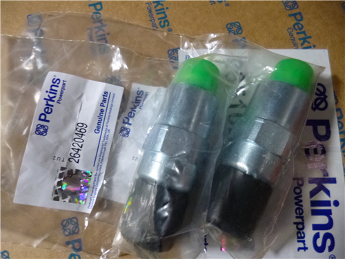
Perkins2306柴油发动机威尔逊P550柴油发电机配件传感器
详细描述
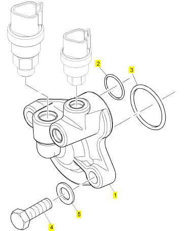
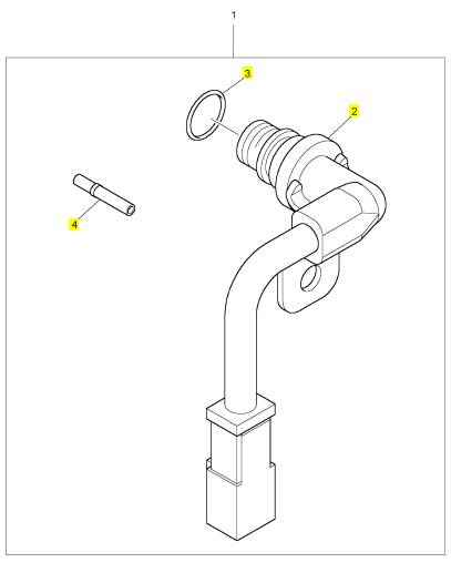
项目 零配件号码 新件号 描述
1 CH10907 1 CH10907 承接器
2 CH10875 1 CH10875 密封O型圈
3 CH10228 1 CH10228 密封O型圈
4 CH10567 2 CH10567 螺拴
5 CH10541 2 CH10255 垫圈
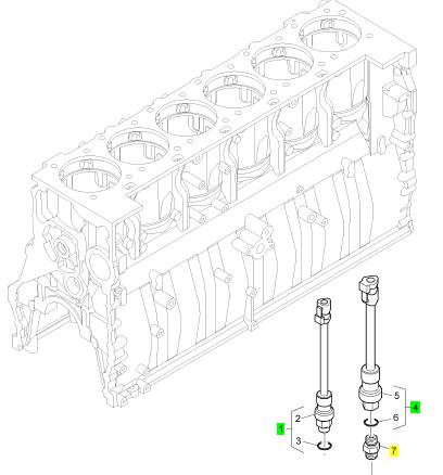
项目 零配件号码 新件号 描述
1 KRP1560 1 KRP1560 气压感应传感器装备
4 KRP1559 1 KRP1559 油压感应传感器装备
7 CH10873 1 CH10873 连接器
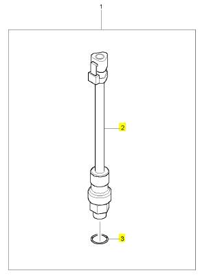
项目 零配件号码 新件号 描述
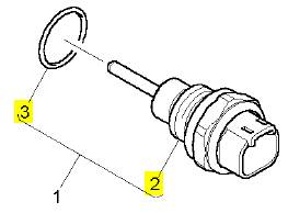
2 1 感应传感器
3 CH10380 1 CH10380 密封O型圈
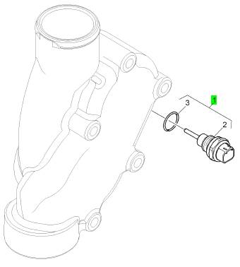
项目 零配件号码 新件号 描述
2 1 速度感应传感器
3 CH10380 1 CH10380 密封O型圈
4 CH11170 2 2900 A016 套筒
项目 零配件号码 新件号 描述
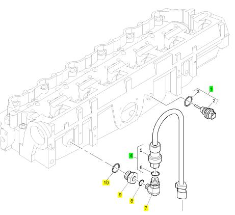
1 KRP1556 1 KRP1556 气温感应传感器装备
4 KRP1558 1 KRP1558 气压感应传感器装备
7 CH10706 1 CH10706 肘管
8 CH10132 1 CH10132 密封O型圈
9 CH10702 1 CH10702 承接器
10 CH10704 1 CH10704 密封O型圈
项目 零配件号码 新件号 描述
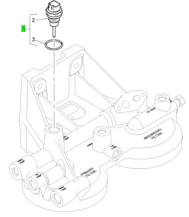
2 1 温度感应传感器
3 CH10871 1 CH10871 密封O型圈 圈
项目 零配件号码 新件号 描述
1 KRP1557 1 KRP1557 感应传感器
项目 零配件号码 新件号 描述
1 KRP1557 1 KRP1557 感应传感器
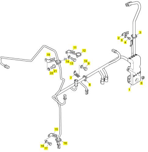
项目 零配件号码 新件号 描述
1 CH10972 1 CH10972 线束
2 CH10071 2 T410794 夹
3 CH10054 2 CH10054 缆拉杆
4 CH10794 2 CH11897 螺拴
5 CH10541 2 CH10255 垫圈
6 CH10290 2 CH10798 螺帽
7 CH10799 2 CH10799 夹
8 CH10054 2 CH10054 缆拉杆
9 CH10797 2 CH10797 螺拴
10 CH10100 2 CH10100 垫圈
11 CH10072 1 CH10072 夹
12 CH10054 1 CH10054 缆拉杆
13 CH10537 1 CH11895 螺拴
14 CH10541 1 CH10255 垫圈
15 CH10072 2 CH10072 夹
16 CH10054 2 CH10054 缆拉杆
17 CH10794 2 CH11897 螺拴
18 CH10541 2 CH10255 垫圈
19 CH10072 1 CH10072 夹
20 CH10054 1 CH10054 缆拉杆
21 CH10796 1 CH10796 螺拴
22 CH10277 1 CH10277 垫圈
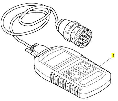
项目 零配件号码 新件号 描述
1 27610337 1 27610337 电子的诊断工具
7.
8.
9.
Turn the flywheel counterclockwise in order to
put the dial indicator at position (D). Write the
measurement in the chart.
Add the lines together in each column.
Subtract the smaller number from the larger
number in column B and column D. Place this
number on line III. The result is the horizontal
eccentricity (out of round). Line III in column C is
the vertical eccentricity.
Vibration Damper - Check
i02553546
Illustration 50
(1) Adapter
(2) Vibration damper
(3) Bolts
(4) Crankshaft pulley
g01287000
Illustration 49
Graph for total eccentricity
(1) Total vertical ecc entricity
(2) Total horizontal eccentricity
(3) Acceptable value
(4) Unacceptable value
g00286046
|
|
vibration damper will increase vibrations. This will
result in damage to the crankshaft.
Replace the damper if any of the following conditions
exist:
from the damper.
excessive heat.
• The damper is bent.
10. Find the intersection of the eccentricity lines
(vertical and horizontal) in Illustration 49.
11. If the point of the intersection is in the “Acceptable”
range, the bore is in alignment. If the point of
intersection is in the “Not acceptable” range, the
flywheel hous ing must be c hanged.
•
•
The bolt holes are worn or there is a loose fit for
the bolts.
The engine has had a crankshaft failure due to
torsional forces.
NOTICE
Inspect the viscous vibration damper for signs of leak-
ing and for signs of damage to the case. Either of
these conditions can cause the weight to contact the
case. This contact can affec t damper operation.
This document has been printed from SPI². Not for Resale
![]()
![]()
![]()
![]() 54
54
Testing and Adjusting Section
KENR6231
Ele ct ri ca l
System
i02555153
When it is possible, make a test of the charging
unit and voltage regulator on the engine, and use
wiring and components that are a permanent part of
the system. Off-engine testing or bench testing will
give a test of the charging unit and voltage regulator
Battery -
Test
operation. This testing will give an indication of
needed repair. After repairs are made, perform a test
in order to prove that the units have been repaired to
the original c ondition of operation.
Most of the tests of the electric al system can be done
on the engine. The wiring insulation must be in good
condition. The wire and cable connections must be
clean, and both components must be tight.
Test
Tools
For
The
Charging
System
Never disconnect any charging unit circuit or bat-
tery circuit cable from the battery when the charg-
ing unit is operated. A spark can cause an explo-
sion from the flammable vapor mixture of hydro-
gen and oxygen that is released from the elec-
trolyte through the battery outlets. Injury to per-
sonnel can be the result.
The battery circuit is an electrical load on the charging
unit. The load is variable because of the condition of
the charge in the battery.
NOTICE
The charging unit will be damaged if the connections
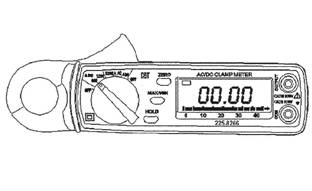
Illustration 51
Typical example of an ammeter
g01012117
between the battery and the charging unit are broken
while the battery is being charged. Damage occurs
because the load from the battery is lost and because
there is an increase in charging voltage. High voltage
will damage the charging unit, the regulator, and other
electrical components.
See Special Ins truction, SEHS7633, “Battery Test
Procedure” for the correct procedures to use to
test the battery. This publication also contains the
specifications to use when you test the battery.
i02554905
Charging System - Test
The condition of charge in the battery at each
regular inspection will show if the charging system is
operating correctly. An adjustment is necessary when
the battery is constantly in a low condition of charge
or a large amount of water is needed. A large amount
of water would be more than one ounce of water per
a cell per a week or per every 100 service hours.
The ammeter is a self-contained instrument that
measures electric al currents without breaking
the circuit and without disturbing the conductor’s
insulation.
The ammeter contains a digital display that is used
to monitor current directly within a range between 1
ampere and 1200 amperes. The multimeter should
be used under only one condition:
• the readings are less than 1 ampere.
A lever opens the ammeter’s jaws over a conductor.
The conductor’s diameter can not be larger than
19 mm (0.75 inch).
The spring loaded jaws clos e around the conductor
for measuring the current. A trigger switch controls
the ammeter. The trigger s witch can be locked into
the ON position or into the OFF position.
After the trigger has been working and the trigger is
turned to the OFF position, the reading appears in
the digital display for five seconds. This accurately
measures currents in areas with a limited access.
For example, these areas include areas that are
beyond the operator’s sight. For DC operation, an
ammeter contains a zero control, and batteries inside
the handle supply the power.
This document has been printed from SPI². Not for Resale
![]()
![]() KENR6231
KENR6231
55
Testing and Adjusting Section
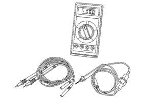
Illustration 52
Typical example of a digital multimeter
g00283566
Electric
Starting
i02554920
System - Test
Most of the tests of the elec trical system can be
done on the engine. The wiring insulation must be
in good c ondition. The wire and cable connections
must be clean, and both components must be tight.
The battery must be fully charged. If the on-engine
test shows a defect in a component, remove the
component for more testing.
The starting system consists of the following four
components:
• Keyswitch
• Start relay
• Starting motor solenoid
• Starting motor
Trouble with the starting system could be caused
by the battery or by charging system problems. If
the battery is suspect, refer to Troubleshooting,
“Battery”. If the starting system is suspect, refer to
Troubleshooting, “Engine Will Not Crank”.
This document has been printed from SPI². Not for Resale
![]() 56
56
Index
Section
KENR6231
Index
A
Air in Fuel - Test..................................................... 23
Air Inlet and Exhaust System .......................... 12, 31
Turbocharger ..................................................... 13
Valves And Valve Mechanism............................ 13
Air Inlet and Exhaust System - Inspect.................. 31
Air Inlet Restriction............................................. 31
B
Basic Engine.................................................... 17, 47
Camshaft............................................................ 18
Crankshaft.......................................................... 18
Cylinder Block Assembly ................................... 17
Cylinder Head Assembly.................................... 18
Pistons, Rings And Connecting Rods ................ 18
Battery - Test ......................................................... 54
Belt Tension Chart ................................................. 22
C
Charging System - Test ......................................... 54
Test Tools For The Charging Sys tem................. 54
Connecting Rod Bearings - Inspect....................... 47
Cooling System ............................................... 16, 41
Cooling System - Check (Overheating) ................. 41
Cooling System - Inspect....................................... 42
Cooling System - Test............................................ 43
Checking the Filler Cap...................................... 44
Test For The Water Temperature Gauge ........... 45
Testing The Radiator And Cooling System For
Leaks................................................................ 44
Cylinder Block - Inspect......................................... 47
Cylinder Liner Projection - Inspect......................... 48
E
Electric Starting System - Test............................... 55
Electrical System............................................. 18, 54
Charging System Components .......................... 19
Engine Electrical System ................................... 19
Grounding Practices .......................................... 18
Starting System Components ............................ 20
Electronic Control System Components .................. 6
Electronic Unit Injector - Adjust ............................. 24
Electronic Unit Injector - Test................................. 24
Engine Crankcase Pressure (Blowby) - Test ......... 35
Engine Oil Pressure - Test..................................... 37
Measuring Engine Oil Pressure ......................... 37
Reason for High Engine Oil Pressure ................ 39
Reasons for Low Engine Oil Pressure............... 38
Engine Valve Lash - Inspect/Adjust ....................... 35
Valve Lash Adjustment ...................................... 36
Valve Lash Check .............................................. 35
Excessive Bearing Wear - Inspect......................... 39
Excessive Engine Oil Consumption - Inspect ........ 39
Engine Oil Leaks into the Combustion Area of the
Cylinders .......................................................... 39
Engine Oil Leaks on the Outside of the Engine .. 39
Exhaust Temperature - Test................................... 34
F
Finding Top Center Position for No. 1 Piston......... 25
Flywheel - Inspect.................................................. 50
Bore Runout (Radial Eccentricity) of the
Flywheel........................................................... 51
Face Runout (Axial Eccentricity) of the
Flywheel........................................................... 50
Flywheel Housing - Inspect ................................... 51
Bore Runout (Radial Eccentricity) of the Flywheel
Housing............................................................ 52
Face Runout (Axial Eccentricity) of the Flywheel
Housing............................................................ 51
Fuel Quality - Test.................................................. 26
Fuel System....................................................... 8, 23
Electronic Unit Injector ........................................ 11
Electronic Unit Injector Mechanism.................... 10
Fuel System Electronic Control Circuit ................ 9
Fuel System - Inspect ............................................ 23
Fuel System - Prime .............................................. 26
Fuel System Pressure - Test ................................. 27
Checking Fuel Pressure..................................... 28
Fuel Pressure Readings .................................... 28
High Fuel Press ure ............................................ 27
Low Fuel Pressure ............................................. 27
G
Gear Group (Front) - Time..................................... 28
Setting Backlash For Camshaft And Adjustable
Idler Gear ......................................................... 29
General Information................................................. 4
Cold Mode Operation........................................... 5
Starting the Engine .............................................. 5
I
Important Safety Information ................................... 2
Increased Engine Oil Temperature - Inspec t ......... 40
L
Lubrication System .......................................... 14, 37
Lubrication System Components ....................... 14
Oil Flow In The Engine....................................... 16
This document has been printed from SPI². Not for Resale
![]() KENR6231
KENR6231
Index
57
Section
M
Main Bearings - Inspect......................................... 47
P
Piston Ring Groove - Inspect................................. 47
Inspect the Clearance of the Piston Ring........... 47
Inspect the Piston and the Piston Rings ............ 47
Inspect the Piston Ring End Gap....................... 47
S
Systems Operation Sec tion ..................................... 4
T
Table of Contents..................................................... 3
Testing and Adjusting ............................................ 22
Testing and Adjusting Section ............................... 22
Turbocharger - Inspect .......................................... 32
Inspection of the Compressor and the Compressor
Housing............................................................ 33
Inspection of the Turbine Wheel and the Turbine
Housing............................................................ 33
V
Vibration Damper - Check ..................................... 53
W
Water Pump - Test ................................................. 46
Water Temperature Regulator - Test ..................... 45
This document has been printed from SPI². Not for Resale
![]() 58
58
Index
Section
KENR6231
This document has been printed from SPI². Not for Resale
![]() KENR6231
KENR6231
Index
59
Section
This document has been printed from SPI². Not for Resale
Copyright © 2005 Perkins Engines Company Limited
All Rights Reserved
Printed in U.K.
This document has been printed from SPI². Not for Resale