 English
 Espaol
 Franais
 阿拉伯
阿拉伯 中文
中文 Deutsch
 Italiano
 Português
 日本
日本 韩国
韩国 български
 hrvatski
 esky
esky Dansk
Dansk Nederlands
 suomi
suomi Ελληνικ
 印度
印度 norsk
norsk Polski
 Roman
Roman русский
 Svenska
Perkins2306柴油发动机威尔逊P550柴油发电机配件CH10931燃油过滤器供应商,Perkins2306柴油发动机威尔逊P550柴油发电机配件CH10931燃油过滤器技术价格规格咨询服务,Perkins2306柴油发动机威尔逊P550柴油发电机配件CH10931燃油过滤器零配件供应,Perkins2306柴油发动机威尔逊P550柴油发电机配件CH10931燃油过滤器售后服务中心,Perkins2306柴油发动机威尔逊P550柴油发电机配件CH10931燃油过滤器,Perkins2306柴油发动机威尔逊P550柴油发电机配件CH10931燃油过滤器详细的技术参数,

产品中心
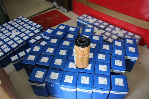
Perkins2306柴油发动机威尔逊P550柴油发电机配件CH10931燃油过滤器
详细描述
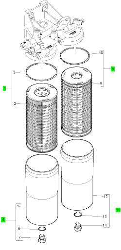
项目 零配件号码 新件号 描述
1 CH10930 1 CH10930 前燃料过滤器
4 CH11094 1 检查历史 过滤器壳
8 CH10931 1 CH10931 燃料过滤器
11 CH11096 1 检查历史 燃料过滤器壳
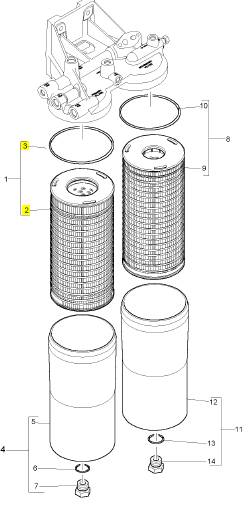
项目 零配件号码 新件号 描述
2 1 燃料过滤器机械要素
3 CH12010 1 CH12010 密封垫
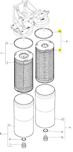
项目 零配件号码 新件号 描述
9 1 燃料过滤器机械要素
10 CH12010 1 CH12010 密封垫
项目 零配件号码 新件号 描述
1 CH11247 1 CH11247 散热器
1 CH11247 1 CH11247 散热器
7 CH11167 1 CH11167 风扇守卫
8 CH11151 1 CH11151 风扇守卫
9 CH11047 1 CH11047 风扇守卫
10 CH11152 1 CH11152 风扇守卫
11 CV70401 20 CV70401 固定螺钉
12 CV70395 20 CV70395 弹簧塾圈
13 CV70392 20 CV70392 垫圈
14 CV70507 4 CV70507 固定螺钉
15 CV70509 4 CV70509 弹簧塾圈
16 CV70508 4 CV70508 垫圈
项目 零配件号码 新件号 描述
1 CH11247 1 CH11247 散热器
1 CH11247 1 CH11247 散热器
项目 零配件号码 新件号 描述
CV25002 1 CH12822 管集箱箱
Y06/00017 1 CH12825 散热器盖
2 CH12819 1 CH12819 加料冷却器
3 CH12822 1 CH12822 管集箱箱
4 CH12825 1 CH12825 散热器盖
5 CH12828 2 CH12828 水管 -冷却器
6 CH12830 4 CH12830 水管夹

Troubleshooting
2506- 15
Industrial
Engine
MGA (Engine)
MGB (Engine)
MGD (Engine)
This document has been printed from SPI². Not for Resale
![]()
![]() Important Safety
Important Safety
Information
Most accidents that involve product operation, maintenance and repair are caused by failure to
observe basic safety rules or precautions. An accident can often be avoided by recognizing potentially
hazardous situations before an accident occurs. A person must be alert to potential hazards. This
person should also have the necessary training, skills and tools to perform these functions properly.
Improper operation, lubrication, maintenance or repair of this product can be dangerous and
could result in injury or death.
Do not operate or perform any lubrication, maintenance or repair on this product, until you have
read and understood the operation, lubrication, maintenance and repair information.
Safety precautions and warnings are provided in this manual and on the product. If these hazard
warnings are not heeded, bodily injury or death could occur to you or to other persons.
The hazards are identified by the “Safety Alert Symbol” and followed by a “Signal Word” such as
“DANGER”, “WARNING” or “CAUTION”. The Safety Alert “WARNING” label is shown below.
The meaning of this safety alert symbol is as follows:
Attention! Become Alert! Your Safety is Involved.
The message that appears under the warning explains the hazard and can be either written or
pictorially presented.
Operations that may cause product damage are identified by “NOTICE” labels on the product and in
this publication.
Perkins cannot anticipate every possible circumstance that might involve a potential hazard. The
warnings in this publication and on the product are, therefore, not all inclusive. If a tool, procedure,
work method or operating technique that is not specifically recommended by Perkins is used,
you must satisfy yourself that it is safe for you and for others. You should also ensure that the
product will not be damaged or be made unsafe by the operation, lubrication, maintenance or
repair procedures that you choose.
The information, specifications, and illustrations in this publication are on the basis of information that
was available at the time that the publication was written. The specifications, torques, pressures,
measurements, adjustments, illustrations, and other items can change at any time. These changes can
affect the service that is given to the product. Obtain the complete and most current information before
you start any job. Perkins dealers or Perkins distributors have the most current information available.
When
replacement
parts
are
required
for
this
product Perkins recommends using Perkins
replacement parts.
Failure to heed this warning can lead to prema-
ture failures, product damage, personal injury or
death.
This document has been printed from SPI². Not for Resale
![]() KENR6224
KENR6224
3
Table of Contents
Table
of
Contents
CID 0003 FMI 11 ................................................... 55
CID 0004 FMI 11 ................................................... 55
CID 0005 FMI 11 ................................................... 56
CID 0006 FMI 11 ................................................... 56
Troubleshoot ing Section
Electronic Troubleshooting
System Overview .................................................... 5
Glossary .................................................................. 7
Electronic Service Tools ........................................ 10
Replacing the ECM ............................................... 12
Self-Diagnostics .................................................... 13
Sensors and Electrical Connectors ....................... 14
Engine Wiring Information .................................... 18
Programming Parameters
Programming Parameters ..................................... 21
Factory Passwords ............................................... 21
Factory Passwords Worksheet ............................. 21
Flash Programming .............................................. 22
Injector Trim File ................................................... 23
System Configuration Parameters
System Configuration Parameters ........................ 24
Troubleshooting without a Diagnostic Code
Alternator Noise .................................................... 31
Alternator Will Not Charge .................................... 31
Battery .................................................................. 31
Can Not Reach Top Engine RPM ......................... 32
Coolant in Engine Oil ............................................ 33
Coolant Temperature Is Too High ......................... 34
ECM Will Not Accept Factory Passwords ............. 34
ECM Will Not Communicate with Other Systems or
Display Modules .................................................. 34
Electronic Service Tool Will Not Communicate with
ECM .................................................................... 35
Engine Cranks but Will Not Start .......................... 36
Engine Has Early Wear ........................................ 37
Engine Misfires, Runs Rough or Is Unstable ........ 38
Engine Oil in Cooling System ............................... 39
Engine Vibration ................................................... 39
Engine Will Not Crank ........................................... 40
Excessive Black Smoke ........................................ 40
Excessive Engine Oil Consumption ...................... 41
Excessive Fuel Consumption ............................... 42
Excessive Valve Lash ........................................... 43
Excessive White Smoke ....................................... 43
Fuel Dilution of Engine Oil .................................... 44
Intermittent Engine Shutdown ............................... 45
Low Engine Oil Pressure ...................................... 46
Low Power ............................................................ 46
Mechanical Noise (Knock) in Engine .................... 47
Noise Coming from Cylinder ................................. 48
Poor Acceleration or Response ............................ 49
Valve Rotator or Spring Lock Is Free .................... 50
Troubleshooting with a Diagnostic Code
Flash Codes .......................................................... 51
Diagnostic Codes .................................................. 51
Diagnostic Code Cross Reference ....................... 52
CID 0001 FMI 11 ................................................... 54
CID 0002 FMI 11 ................................................... 55
CID 0041 FMI 03 .................................................. 56
CID 0041 FMI 04 .................................................. 57
CID 0091 FMI 08 .................................................. 57
CID 0100 FMI 03 .................................................. 57
CID 0100 FMI 04 .................................................. 57
CID 0110 FMI 03 ................................................... 58
CID 0110 FMI 04 ................................................... 58
CID 0168 FMI 02 .................................................. 58
CID 0172 FMI 03 .................................................. 59
CID 0172 FMI 04 .................................................. 59
CID 0174 FMI 03 .................................................. 59
CID 0174 FMI 04 .................................................. 59
CID 0190 FMI 02 .................................................. 60
CID 0190 FMI 09 .................................................. 60
CID 0190 FMI 11 ................................................... 60
CID 0190 FMI 12 .................................................. 61
CID 0247 FMI 09 .................................................. 61
CID 0248 FMI 09 .................................................. 61
CID 0253 FMI 02 .................................................. 61
CID 0254 FMI 12 .................................................. 62
CID 0261 FMI 13 .................................................. 62
CID 0262 FMI 03 .................................................. 62
CID 0262 FMI 04 .................................................. 63
CID 0268 FMI 02 .................................................. 63
CID 0273 FMI 03 .................................................. 63
CID 0273 FMI 04 .................................................. 63
CID 0274 FMI 03 .................................................. 64
CID 0274 FMI 04 .................................................. 64
CID 0342 FMI 02 .................................................. 64
CID 0342 FMI 11 ................................................... 65
CID 0342 FMI 12 .................................................. 65
CID 0799 FMI 12 .................................................. 65
CID 1690 FMI 08 .................................................. 66
Troubleshooting with an Event Code
Event Codes ........................................................ 67
E162 High Boost Pressure ................................... 69
E360 Low Engine Oil Pressure ............................. 70
E361 High Engine Coolant Temperature .............. 71
E362 Engine Overspeed ....................................... 72
E363 High Fuel Supply Temperature .................... 72
E368 High Intake Manifold Air Temperature ......... 73
Diagnostic Functional Tests
5 Volt Engine Pressure Sensor Supply Circuit -
Test ..................................................................... 75
CAN Data Link Circuit - Test ................................. 81
Data Link Circuit - Test .......................................... 85
ECM Memory - Test .............................................. 88
Electrical Connectors - Inspect ............................. 90
Electrical Power Supply Circuit - Test ................... 94
Engine Pressure Sensor Open or Short Circuit -
Test ..................................................................... 97
Engine Speed/Timing Sensor Circuit - Test ........ 103
Engine Temperature Sensor Open or Short Circuit -
Test .................................................................... 110
Indicator Lamp Circuit - Test ................................ 115
Injector Solenoid Circuit - Test ............................. 119
Speed Control (Analog) - Test ............................ 126
This document has been printed from SPI². Not for Resale
![]() 4
4
Table of Contents
KENR6224
Speed Control (PWM) - Test ............................... 129
Switch Circuits - Test .......................................... 134
Calibration Procedures
Engine Speed/Timing Sensor - Calibrate ............ 138
Index Section
Index ................................................................... 140
This document has been printed from SPI². Not for Resale
![]()
![]() KENR6224
KENR6224
5
Troubleshooting Section
Troubleshoot ing
Section
Ele ct ron ic
Trou bl es hoot ing
System Overview
i02547521
System Operation
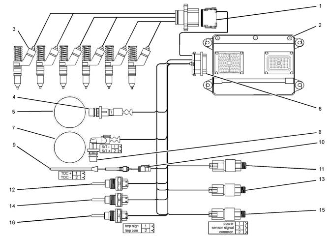
Illustration 1
Block diagram for the 2506-15 engine
(1) 12 Pin Connector
(2) Electronic Control Module (ECM)
(3) Electronic Unit Injectors
(4) Crankshaft Position Sensor
(5) 36 - 1 Tooth Gear
(6) 120 Pin Connector
(7) 36 + 1 Tooth Gear
(8) Camshaft Position Sensor
(9) Timing Calibration Probe
(10) Timing Calibration Probe Connector
(11) Atmospheric Pressure Sensor
(12) Inlet Manifold Temperature Sensor
g01277565
(13) Inlet Manifold Pressure Sensor
(14) Coolant Temperature Sensor
(15) Engine Oil Pressure Sensor
(16) Fuel Temperature Sensor
This engine is electronically controlled. Each cylinder
has an electronic unit injector. The Electronic Control
Module (ECM) sends a signal to each injector
solenoid in order to control the operation of the fuel
injection system.
This document has been printed from SPI². Not for Resale
![]() 6
6
Troubleshooting Section
KENR6224
Electronic Cont rols
The electronic system consists of the following
components: the ECM, the Mechanically Actuated
Electronically Controlled Unit Injectors (MEUI), the
wiring harness, the switches, and the sensors. The
ECM is the computer. The flash file is the software
for the computer. The flash file contains the operating
maps. The operating maps define the following
characteristics of the engine:
• Horsepower
• Torque curves
The ECM determines the timing and the amount of
fuel that is delivered to the cy linders. These decisions
are based on the ac tual conditions and/or on the
desired conditions at any given time.
The ECM compares the desired engine speed to
the actual engine speed. The actual engine speed is
determined through the engine speed/timing sensor.
The desired engine speed is determined with the
following factors:
• Throttle signal
• Other input signals from sensors
• Certain diagnostic codes
If the desired engine speed is greater than the actual
engine speed, the ECM injects more fuel in order to
increase the actual engine speed.
Fuel Injection
The ECM controls the amount of fuel that is injected
by varying the signals to the injectors. The injector will
pump fuel only if the injector solenoid is energized.
The ECM sends a high voltage signal to the solenoid.
This high voltage signal energizes the solenoid. By
controlling the timing and the duration of the high
voltage signal, the ECM can c ontrol injection timing
and the ECM can control the amount of fuel that is
injected.
The ECM limits engine power during cold mode
operation and the ECM modifies injection timing
during cold mode operation. Cold mode operation
provides the following benefits:
• Increased cold weather starting capability
• Reduced warm-up time
• Reduced white smoke
Cold mode is activated whenever the engine
temperature falls below a predetermined value. Cold
mode remains active until the engine temperature
rises above a predetermined value or until a time
limit is exceeded.
The flash file inside the ECM sets certain limits on
the amount of fuel that can be injected. The “FRC
Fuel Limit” is used to control the air/fuel ratio for
control of emissions. The “FRC Fuel Limit” is a limit
that is based on the turbocharger outlet pressure.
A higher turbocharger outlet pressure indicates that
there is more air in the cylinder. When the ECM
senses a higher turbocharger outlet pressure, the
ECM increases the “FRC Fuel Limit”. When the ECM
increases the “FRC Fuel Limit”, the ECM allows
more fuel into the cylinder. The “FRC Fuel Limit” is
programmed into the ECM at the factory. The “FRC
Fuel Limit” cannot be changed.
The “Rated Fuel Limit” is a limit that is based on the
power rating of the engine and on engine rpm. The
“Rated Fuel Limit” is similar to the rack stops and to
the torque spring on a mechanically governed engine.
The “Rated Fuel Limit” provides the power curves
and the torque curves for a specific engine family and
for a spec ific engine rating. The “Rated Fuel Limit” is
programmed into the ECM at the factory. The “Rated
Fuel Limit” cannot be changed.
Once the ECM determines the amount of fuel that
is required, the ECM must determine the timing of
the fuel injection. The ECM uses the signal from the
camshaft position sensor to c alculate the top center
pos ition of eac h cylinder . The ECM decides when
fuel injection should occur relative to the top center
pos ition and the ECM provides the signal to the
injector at the desired time. The ECM adjusts timing
for optimum engine performance, for optimum fuel
economy, and for optimum control of white smoke.
Programmable Parameters
Certain parameters that affect the engine operation
may be changed with the Perkins Electronic
Service Tool (EST). The parameters are stored
in the ECM, and some parameters are protected
from unauthorized changes by passwords. These
pas swords are c alled factory passwords.
Passwords
Several system configuration parameters and most
logged events are protected by factory passwords .
Factory passwords are available only to Perkins
dealers and distributors. Refer to Troubleshooting,
“Factory Passwords” for additional information.
This document has been printed from SPI². Not for Resale
![]() KENR6224
KENR6224
7
Troubleshooting Section
i02554801
Crankshaft Position Sensor
– This sensor
Glossary
Active Diagnostic Code
– An active diagnostic
determines the position of the crankshaft during
engine operation. If the crankshaft position sensor
fails during engine operation, the camshaft position
sensor is used to provide the signal.
Data Link – The Data Link is a serial communication
code alerts the operator or the service technician that
an electronic system malfunction is currently present.
Refer to the term “Diagnostic Code” in this glossary.
Adaptive Trim – This is a software process that is
performed in the Electronic Control Module (ECM)
that optimizes engine performance.
Alternating Current (AC) – Alternating current is an
electric current that reverses direction at a regular
interval that is reoccurring.
Before Top Center (BTC) – BTC is the 180 degrees
of crankshaft rotation before the piston reaches the
top dead center position in the normal direction of
rotation.
Breakout Harness – A breakout harness is a
test harness that is designed to connect into the
engine harness. This connection allows a normal
circuit operation and the connection simultaneously
provides a Breakout T in order to measure the
signals.
Bypass Circuit – A bypass circuit is a circuit that is
used as a substitute circuit for an existing circuit. A
bypass circ uit is typically used as a test circuit.
Camshaft Position Sensor – This sensor
determines the position of the camshaft during
engine operation. If the crankshaft position sensor
fails during engine operation, the camshaft position
sensor is used to provide the signal.
CAN Data Link (see also J1939 CAN Data Link) –
The CAN Data Link is a serial communications
port that is used for communication with other
microprocessor based devices.
Code – Refer to “Diagnostic Code” or “Event Code”.
Communication Adapter Tool – The
communication adapter provides a communication
link between the ECM and the electronic service tool.
Component Identifier (CID) – The CID is a number
that identifies the specific component of the electronic
control system that has experienced a diagnostic
code.
Coolant Temperature Sensor – The coolant
temperature sensor detects the engine coolant
temperature for all normal operating conditions and
for engine monitoring.
port that is used for communication with other devices
such as the electronic service tool.
Derate – Certain engine conditions will generate
event codes. Also, engine derates may be applied.
The map for the engine derate is programmed into
the ECM software. The derate can be one or more of
3 types: reduction of rated power, reduction of rated
engine speed, and reduction of rated machine speed
for OEM products.
Desired Engine Speed – The desired engine speed
is input to the electronic governor within the ECM.
The electronic governor uses the signal from the
throttle position sensor, the engine speed/timing
sensor, and other sensors in order to determine the
desired engine speed.
Diagnostic Code – A diagnostic code is sometimes
referred to as a fault code. These codes indicate an
electronic system malfunction.
Diagnostic Lamp – A diagnostic lamp is sometimes
called the check engine light. The diagnostic lamp
is used to warn the operator of the presence of
an active diagnostic code. The lamp may not be
included in all applications.
Digital Sensor Return – The common line (ground)
from the ECM is used as ground for the digital
sensors.
Digital Sensors – Digital sensors produce a pulse
width modulated signal. Digital sensors are supplied
with power from the ECM.
Digital Sensor Supply – The power supply for the
digital s ensors is provided by the ECM.
Direct Current (DC) – Direct current is the type of
current that flows consistently in only one direction.
DT, DT Connector, or Deutsch DT – This is a type
of connector that is used on Perkins engines. The
connectors are manufactured by Deutsch.
Duty Cycle – Refer to “Pulse Width Modulation”.
Electronic Engine Control – The electronic
engine control is a complete electronic system.
The electronic engine control monitors the engine
operation under all conditions. The electronic engine
control also controls the engine operation under all
conditions.
This document has been printed from SPI². Not for Resale
![]() 8
8
Troubleshooting Section
KENR6224
Electronic Control Module (ECM) – The ECM
7
– The mechanic al system is not responding
is the control computer of the engine. The ECM
provides power to the electronics. The ECM monitors
data that is input from the sensors of the engine. The
ECM acts as a governor in order to control the speed
and the power of the engine.
Electronic Service Tool – The electronic service
tool allows a computer (PC) to communicate with the
ECM.
Engine Monitoring – Engine Monitoring is the part
of the electronic engine control that monitors the
sensors. This also warns the operator of detected
faults.
Engine Oil Pressure Sensor – The engine oil
pressure sensor measures engine oil pressure. The
sensor sends a signal to the ECM that is dependent
on the engine oil pressure.
Engine Position Sensor – An engine position
sensor is a hall effect switc h that provides a digital
signal to the ECM. The ECM interprets this signal as
the crankshaft position and the engine speed. Two
sensors are used to provide the speed and timing
signals to the ECM. The crankshaft position sensor
is associated with the crankshaft and the camshaft
position sensor is associated with the camshaft.
Event Code – An event code may be activated
in order to indicate an abnormal engine operating
condition. These codes usually indicate a mechanical
fault instead of an electrical system fault.
Failure Mode Identifier (FMI) – This identifier
indicates the type of failure that is associated with
the component. The FMI has been adopted from the
SAE practice of J1587 diagnostics. The FMI follows
the parameter identifier (PID) in the descriptions of
the fault code. The descriptions of the FMIs are in
the following list.
0 – The data is valid but the data is above the normal
operational range.
1 – The data is valid but the data is below the normal
operational range.
2 – The data is erratic, intermittent, or incorrect.
3 – The voltage is above normal or the voltage is
shorted high.
4 – The voltage is below normal or the voltage is
shorted low.
5 – The current is below normal or the circuit is open.
6 – The current is above normal or the circuit is
grounded.
properly.
8 – There is an abnormal frequency, an abnormal
pulse width, or an abnormal time period.
9 – There has been an abnormal update.
10 – There is an abnormal rate of change.
11 – The failure mode is not identifiable.
12 – The device or the component is damaged.
Flash File – This file is software that is inside
the ECM. The file contains all the instructions
(software) for the ECM and the file contains the
performance maps for a specific engine. The file may
be reprogrammed through flash programming.
Flash Programming – Flash programming is the
method of programming or updating an ECM with
an electronic servic e tool over the data link instead
of replacing components.
Fuel Injector E-Trim – Fuel injector E-trim is a
software process that allows precise control of fuel
injectors by parameters that are programmed into
the ECM for eac h fuel injector. With the use of the
electronic service tool, the service technician can
read status information for the E-Trim. Data for
E-Trim can also be programmed.
FRC – See “Fuel Ratio Control”.
Fuel Ratio Control (FRC) – The FRC is a limit that
is based on the control of the ratio of the fuel to air.
The FRC is used for purposes of emission control.
When the ECM senses a higher intake manifold
air pressure (more air into the cylinder), the FRC
increases the FRC Limit (more fuel into the cylinder).
Full Load Setting (FLS) – The FLS is the parameter
that represents the fuel system adjustment. This
adjustment is made at the factory in order to fine tune
the fuel system. The correct value for this parameter
is stamped on the engine information ratings plate.
This parameter must be programmed.
Full Torque Setting (FTS) – The FTS is the
parameter that represents the adjustment for the
engine torque. This adjustment is made at the factory
in order to fine tune the fuel system. This adjustment
is made in conjunction with the FLS. This parameter
must be programmed.
Harness – The harness is the bundle of wiring
(loom) that connects all components of the electronic
system.
This document has been printed from SPI². Not for Resale
![]()
![]() KENR6224
KENR6224
9
Troubleshooting Section
Hertz (Hz)
– Hertz is the measure of electrical
Password – A password is a group of numeric
frequency in cycles per second.
Injector Codes – The injector codes or injector trim
codes are numeric codes or alphanumeric codes
that are etched or stamped on individual electronic
unit injectors. These codes are used to fine tune the
fuel delivery.
Injector Trim Files – Injector trim files are
downloaded from a disk to the ECM. The injector
trim files compensate for variances in manufacturing
of the electronic unit injector and for the life of the
electronic unit injector. The serial number for the
electronic unit injector must be obtained in order to
retrieve the correct injector trim file.
Intake Manifold Air Temperature Sensor – The
intake manifold air temperature sensor detec ts the
air temperature in the intake manifold. The ECM
monitors the air temperature and other data in the
intake manifold in order to adjust injection timing and
other performance functions .
Intake Manifold Pressure Sensor – The Intak e
Manifold Pressure Sensor measures the pressure
in the intake manifold. The pressure in the intake
manifold may be different to the pressure outside
the engine (atmospheric pressure). The difference
in pressure may be caused by an increase in air
pressure by a turbocharger (if equipped).
Integrated Electronic Controls – The engine is
designed with the electronic controls as a necessary
part of the system. The engine will not operate
without the electronic controls.
J1939 CAN Data Link – This data link is a SAE
standard diagnostic c ommunications data link that
is used to communicate between the ECM and the
electronic dev ices.
Logged Diagnostic Codes – Logged diagnostic
codes are codes which are stored in the memory.
These codes are meant to be an indicator of
possible causes for intermittent faults. Refer to the
term “Diagnostic Code” in this glossary for more
information.
OEM – OEM is an abbreviation for the Original
Equipment Manufacturer. This is the manufacturer of
the machine or the vehicle that uses the engine.
Open Circuit – An open circuit is a condition that is
caused by an open switch, or by an elec trical wire
or a connection that is broken. When this condition
exists, the signal or the supply voltage can no longer
reach the intended destination.
Parameter – A parameter is a value or a limit that
is programmable. This helps determine specific
characteristics or behaviors of the engine.
|
that is designed to restrict acc ess to parameters. The
electronic system requires correct passwords in order
to change some parameters (Factory Passwords).
Refer to Troubleshooting, “Factory Passwords” for
more information.
Personality Module – See “Flash File”.
Power Cycled – Power cycled happens when power
to the ECM is cycled: ON, OFF, and ON. Power
cycled refers to the action of cycling the k eyswitch
from any position to the OFF position, and to the
START/RUN position.
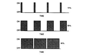
Pulse Width Modulation (PWM) – The PWM is a
signal that consists of pulses that are of variable
width. These pulses occur at fixed intervals. The ratio
of “TIME ON” versus total “TIME OFF” c an be varied.
This ratio is also referred to as a duty cycle.
Illustration 2
Rated Fuel Limit – This is a limit that is based on
the power rating of the engine and on the engine rpm.
The Rated Fuel Limit enables the engine power and
torque outputs to conform to the power and torque
curves of a specific engine model. These limits are in
the flash file and these limits cannot be changed.
Reference Voltage – Reference voltage is a
regulated voltage and a steady voltage that is
supplied by the ECM to a sensor. The reference
voltage is used by the sensor to generate a signal
voltage.
Relay – A relay is an electromec hanical switc h. A
flow of electricity in one circuit is used to control the
flow of electricity in another circuit. A small current or
voltage is applied to a relay in order to switch a much
larger current or voltage.
Sensor – A sens or is a device that is used to
detect the current value of pressure or temperature,
or mechanical movement. The information that is
detected is converted into an electrical signal.
This document has been printed from SPI². Not for Resale
| |||||||||||||||||||||||||||
Troubleshooting Section
KENR6224
Short Circuit – A short circuit is a condition that has
an electrical circuit that is inadvertently connected to
an undesirable point. An example of a short circuit
is a wire which rubs against a vehicle frame and
this rubbing eventually wears off the wire insulation.
Electrical contact with the frame is made and a s hort
circuit results.
Signal – The signal is a voltage or a waveform that
is used in order to transmit information ty pically from
a sensor to the ECM.
•
•
•
•
•
Obtain data.
Diagnose faults.
Read parameters.
Program parameters.
Calibrate sensors.
Supply Voltage – The supply voltage is a continuous
voltage that is supplied to a component in order to
provide the elec trical power that is required for the
component to operate. The power may be generated
by the ECM or the power may be battery voltage that
is supplied by the engine wiring.
System Configuration Parameters – System
configuration parameters are parameters that affect
emiss ions and/or operating charac teristics of the
engine.
Tattletale – Certain parameters that affect the
operation of the engine are stored in the ECM.
These parameters can be changed by use of the
electronic service tool. The tattletale logs the number
of changes that have been made to the parameter.
The tattletale is stored in the ECM.
Throttle Position – The throttle position is the
interpretation by the ECM of the signal from the
throttle position sensor or the throttle switch.
Timing Calibration – The timing calibration is the
adjustment of an electrical signal. This adjustment is
made in order to correct the timing error between the
camshaft and the engine speed/timing sensors or
between the crankshaft and the engine speed/timing
sensors.
Top Center Position – The top center position refers
to the crankshaft position when the engine piston
position is at the highest point of travel. The engine
must be turned in the normal direction of rotation in
order to reach this point.
Total Tattletale – The total tattletale is the total
number of changes to all the parameters that are
stored in the ECM.
i02547729
Electronic Service Tools
Perkins Electronic Service Tools are designed to help
the service technician:
Required Service Tools
The tools that are listed in Table 1 are required in
order to enable a service technician to perform the
procedures.
Table 1
Two short jumper wires are needed to check the
continuity of some wiring harness circuits by shorting
two adjacent terminals together in a connector. A
long extension wire may also be needed to check the
continuity of some wiring harness circuits.
Perkins Electronic Service Tool
(EST)
The Perkins EST can display the following
information:
• Parameters
• Event codes
• Diagnostic codes
• Engine configuration
This document has been printed from SPI². Not for Resale
![]()
![]()
![]() KENR6224
KENR6224
11
Troubleshooting Section
The Perkins EST can be used by the technician to
perform the following functions:
• Diagnostic tests
• Sensor calibration
• Flash programming
• Set parameters
Table 2 lists the service tools that are required in
order to use Perkins EST.
Table 2
Connecting Perkins EST and the
Communication Adapter II
|
Service Tools for the Use of Perkins EST | |
|
Part Number |
Description |
|
-(1) |
Personal Computer (PC) |
|
-(1) |
<, TD vAlign=top width=231>
|
|
-(1) |
Data Subscription for All Engines |
|
27610251 |
Communi cation Adapter Gp |
|
27610164(2) |
Adapter Cable As |
(1)
(2)
Refer to the Perkins Engine Company Limited.
The 27610164 Adapter Cable As is required to connect to the
USB port on computers that are not equipped with a RS232
serial port.
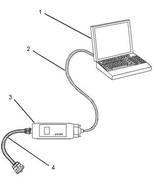
Illustration 3
(1) Personal computer (PC)
g01115382
Note: For more information regarding the use of
Perkins EST and the PC requirements for Perkins
EST, refer to the documentation that accompanies
your Perkins EST software.
(2) Adapter Cable (RS232 Port)
(3) Communication Adapter As
(4) Adapter Cable As
Note: Items (2), (3), and (4) are part of the 27610251
Communication Adapter Gp.
Use the following procedure in order to c onnect
Perkins EST and the Communication Adapter II.
1. Turn the keyswitch to the OFF position. If the
keyswitch is not in the OFF position, the engine
may start.
2. Connect cable (2) between the “COMPUTER”
end of communication adapter (3) and the RS232
serial port of PC (1).
Note: An adapter cable assembly is required to
connect to the USB port on computers that are not
equipped with a RS232 serial port.
3. Connect cable (4) between the “DATA LINK” end
of communication adapter (3) and the diagnostic
connector.
This document has been printed from SPI². Not for Resale