 English
 Espaol
 Franais
 阿拉伯
阿拉伯 中文
中文 Deutsch
 Italiano
 Português
 日本
日本 韩国
韩国 български
 hrvatski
 esky
esky Dansk
Dansk Nederlands
 suomi
suomi Ελληνικ
 印度
印度 norsk
norsk Polski
 Roman
Roman русский
 Svenska
Perkins2306柴油发动机威尔逊P550柴油发电机配件CH11218涡轮增压器供应商,Perkins2306柴油发动机威尔逊P550柴油发电机配件CH11218涡轮增压器技术价格规格咨询服务,Perkins2306柴油发动机威尔逊P550柴油发电机配件CH11218涡轮增压器零配件供应,Perkins2306柴油发动机威尔逊P550柴油发电机配件CH11218涡轮增压器售后服务中心,Perkins2306柴油发动机威尔逊P550柴油发电机配件CH11218涡轮增压器,Perkins2306柴油发动机威尔逊P550柴油发电机配件CH11218涡轮增压器详细的技术参数,

产品中心
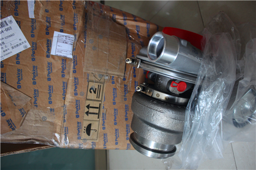
Perkins2306柴油发动机威尔逊P550柴油发电机配件CH11218涡轮增压器
详细描述
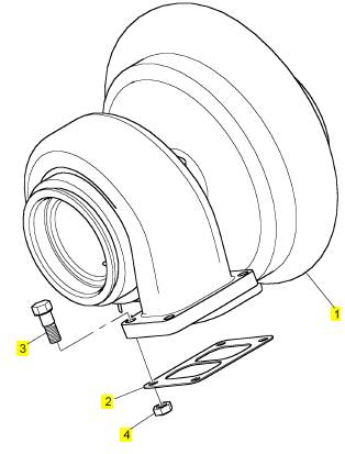
项目 零配件号码 新件号 描述
1 CH11218 1 CH11218 涡轮增压器
1 P/CH11218 1 CH11218 涡轮增压器
1 CH11218 1 CH11218 涡轮增压器
(1) P/CH11218 1 CH11218 涡轮增压器
(1) CH11218 1 CH11218 涡轮增压器
2 CH11471 1 CH11471 密封垫 -涡轮增压器
2 CH10014 1 CH11471 密封垫 -涡轮增压器
3 CH10733 4 CH10733 螺拴
4 CH10734 4 CH10734 锁紧螺母
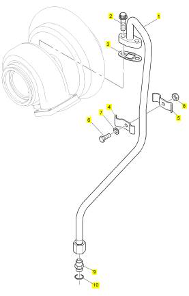
项目 零配件号码 新件号 描述
1 CH11219 1 CH11219 管 - 涡轮增压器的油补给
2 CH11225 2 CH11225 螺拴
3 CH10805 1 CH10805 密封垫
4 CH10915 1 CH10915 摇臂座
5 CH10915 1 CH10915 摇臂座
6 CH10815 1 CH10815 螺拴
7 CH10916 1 CH10916 垫圈
8 CH10290 1 CH10798 螺帽
9 CH10806 1 CH10806 连接器
10 CH10667 1 CH10667 密封O型圈
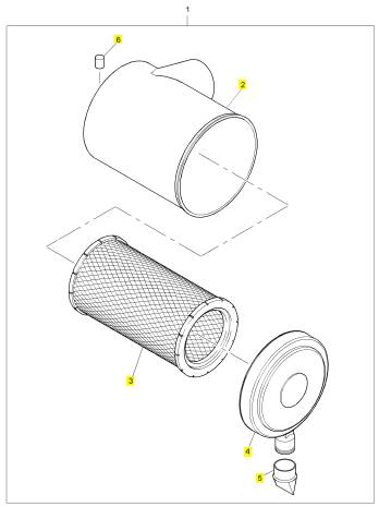
项目 零配件号码 新件号 描述
2 1 空气过滤器体
3 CH11217 1 CH11217 主空气过滤器
4 CH11288 1 CH11288 盖
5 26510350 1 26510350 阀
6 CV10891 1 CV10891 帽
6 CH11277 1 CV10891 帽
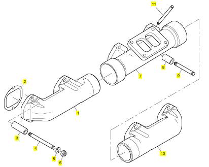
项目 零配件号码 新件号 描述
1 CH10774 1 CH10774 排出岐管
2 CH10777 6 CH10777 密封垫 - 排出岐管
3 CH10776 11 CH10776 间隔器
4 CH10775 11 CH10775 图钉
5 CH10541 12 CH10255 垫圈
6 CH10734 12 CH10734 锁紧螺母
7 T400179 1 T400179 排出岐管
7 CH10901 1 T400179 排出岐管
8 CH10756 1 CH10756 间隔器
9 CH10772 1 CH10772 图钉
10 CH10774 1 CH10774 排出岐管
11 T400180 4 T400180 图钉
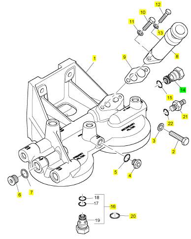
项目 零配件号码 新件号 描述
1 CH12434 1 CH12434 燃料过滤器
1 CH11075 1 CH12434 燃料过滤器
2 CH10609 1 CH10609 螺拴
3 CH10255 1 CH10255 垫圈
3 CH10541 1 CH10255 垫圈
4 CH10286 1 CH10286 栓塞
5 CH11880 1 CH11880 密封O型圈
5 CH10046 1 CH10046 密封O型圈
6 CH10287 1 CH10287 栓塞
7 T406205 1 T406205 密封O型圈
7 CH10048 1 CH10048 密封O型圈
8 CH10439 1 CH10439 汽酒共腾泵
9 CH10008 1 CH10008 密封垫
10 CH10557 1 CH10557 螺拴
11 CH10277 1 CH10277 垫圈
11 CH10131 1 CH10131 密封O型圈
12 CH10848 1 CH10848 螺拴
13 CH10086 1 CH10086 垫圈
14 CH10836 1 CH10836 阀
15 T400188 1 T400188 密封O型圈
16 CH12017 1 CH12017 非回路阀
16 CH10457 1 检查历史 阀
16 CH12017 1 CH12017 非回路阀
20 CH10131 1 CH10131 密封O型圈
21 CH11410 1 CH11410 栓塞
22 CH11880 1 CH11880 密封O型圈
23 CH11411 1 CH11411 灰尘盾
4.
Place the keyswitch in the ON position. If the
Perkins EST and the communication adapter
do not communicate with the Elec tronic Control
Module (ECM), refer to the diagnostic procedure
Troubleshooting, “Electronic Service Tool Will Not
Communicate With ECM”.
i02548810
1.
Rec ord the configuration data:
a. Connec t the electronic service tool to the
diagnostic connector. Refer to Troubleshooting,
“Electronic Service Tools”.
b. Print the parameters from the “Configuration”
screen on the electronic service tool. If a printer
is unavailable, record all of the parameters.
Record any logged diagnos tic codes and
Replacing
the
ECM
logged event codes for your records. Record
the injector codes from the “Calibrations”
screen in the “Service” menu on the electronic
service tool.
NOTICE
Keep all parts clean from contaminants.
c.
Use the “Copy
Configuration/ECM
Contaminants may cause rapid wear and shortened
component life.
The Electronic Control Module (ECM) contains no
moving parts. Replacement of the ECM can be
costly. Replacement can also be a time consuming
task. Follow the troubleshooting procedures in this
manual in order to ensure that replacing the ECM will
correct the fault. Verify that the suspect ECM is the
cause of the fault.
Note: Ensure that the ECM is receiving power and
that the ECM is properly wired to the negative battery
circuit before a replacement of the ECM is attempted.
Refer to Troubleshooting, “Electrical Power Supply
Circuit - Test”.
A test ECM can be used to determine if the ECM is
faulty. Install a test ECM in place of the suspect ECM.
Flash program the correct flash file into the test ECM.
Program the parameters for normal operation of the
engine. The parameters must match the parameters
in the suspect ECM. Refer to the following test steps
for details. If the test ECM resolves the fault, connect
the suspect ECM. Verify that the fault returns. If the
fault returns, replace the suspect ECM.
Note: When a new ECM is not available, you may
need to remove an ECM from an engine that is not
in service. The interlock code for the replacement
ECM mus t match the interlock code for the suspect
ECM. Be sure to record the parameters from the
replacement ECM on the “Parameters Worksheet”.
Use the “Copy Configuration/ECM Replacement”
feature that is found under the “Service” menu on
the electronic service tool.
NOTICE
If the flash file and engine application are not matched,
engine damage may result.
Perform the following procedure in order to replace
the ECM:
Replacement” feature that is found under the
“Service” menu on the electronic serv ice tool.
Select “Load from ECM” in order to copy the
configuration data from the suspect ECM.
Note: If the “Copy Configuration” process fails and
the parameters were not obtained in Step 1.b, the
parameters must be obtained elsewhere. Some of the
parameters are stamped on the engine information
plate. Most of the parameters must be obtained from
the factory.
2. Remove the ECM:
a. Turn the keyswitch to the OFF position.
b. Disconnect the P1 and P2 connectors from
the ECM.
c. Disconnect the ECM ground s trap.
d. Remove the mounting bolts from the ECM.
3. Install the replacement ECM:
a. Use the old mounting hardware to install the
replacement ECM.
b. Connec t the ECM ground strap.
c. Connec t the P1 and P2 connectors. Tighten
the ECM connector (allen head screw) to
the proper torque. Refer to Troubleshooting,
“Electrical Connectors - Inspect” for the correct
torque value.
4. Configure the replacement ECM:
a. Flash program the flash file into the ECM.
Refer to Troubleshooting, “Flash Programming”
for the correct procedure.
This document has been printed from SPI². Not for Resale
![]() KENR6224
KENR6224
13
Troubleshooting Section
b. Use the electronic service tool to match the
engine application and the interlock code if
the replacement ECM was used for a different
application.
c. If the “Copy Configuration” process from
Step 1.b was successful, return to the “Copy
Configuration/ECM Replacement” screen on
the electronic service tool and select “Program
ECM”. Proceed to Step 4.e when programming
is c omplete.
d. If the “Copy Configuration” process from Step
1.b was unsuccessful, manually program the
ECM parameters. The parameters must match
the parameters from Step 1.b.
e. Program the engine monitoring system, if
necessary.
f. Load the injector trim files for the injectors.
Refer to Troubleshooting, “Injector Trim File”.
g. Calibrate the engine speed/timing. Refer
to Troubleshooting, “Engine Speed/Timing
Sensor - Calibrate”.
Every generated code is stored in the permanent
memory of the ECM. The codes are logged.
Logged codes may not indicate that a repair is
needed. The fault may have been temporary. The
fault may have been resolved since the logging of
the code. If the system is powered, it is possible
to generate an active diagnostic code whenever a
component is disconnected. When the component is
reconnected, the code is no longer active. Logged
codes may be useful to help troubleshoot intermittent
faults. Logged codes can also be used to review
the performance of the engine and of the electronic
system.
Event Code
An event code is generated by the detection of an
abnormal engine operating condition. For example,
an event code will be generated if the oil pressure is
too low. In this case, the event c ode indicates the
symptom of a fault.
Self-Diagnostics
i02548823
The Electronic Control Module (ECM) has the ability
to detect faults with the electronic sys tem and with
engine operation. When a fault is detected, a code is
generated. An alarm may also be generated. There
are two types of codes:
• Diagnostic
• Event
Diagnostic Code – When a fault with the electronic
system is detected, the ECM generates a diagnostic
code. This indicates the specific fault with the
circuitry.
Diagnostic codes can have two different states:
• Active
• Logged
Active Code
An active diagnostic code indicates that an active
fault has been detected. Activ e c odes require
immediate attention. Always service active codes
prior to servicing logged codes.
Logged Code
This document has been printed from SPI². Not for Resale
![]() 14
14
Troubleshooting Section
KENR6224
Sensors
and
Electrical
i02548835
Connectors
Table 3
|
Connector |
Function |
|
J1/P1 |
ECM Connector (70-Pin Engine Harness) |
|
J2/P2 |
ECM Connector (“120-Pi n Engine Harness”) |
|
J61/P61 |
Customer Connector (Optional) (40-Pin Connector) |
|
J63/P63 |
Diagnostic Connector (9-Pin Connector) |
|
J100/P100 |
Coolant Temperature Sensor (2-Pin Connector) |
|
J103/P103 |
Inlet Manifold Temperature Sensor (2-Pin Connector) |
|
J105/P105 |
Fuel Temperature Sensor (2-Pin Connector) |
|
J200/P200 |
Inlet Manifold Pressure Sensor (3-Pin Connector) |
|
J201/P201 |
Engine Oil Pressure Sensor (3-Pin Connector) |
|
J203/P203 |
Atmospheric Pressure Sensor (3-Pin Connector) |
|
J300/P300 |
Injector Solenoid Harness (12-Pin Connector) |
|
J400/P400 |
Engine Timing Cal ibr ation Probe (2-Pin Connector) |
|
J401/P401 |
Crankshaft Position Sensor (2-Pin Connector) |
|
J402/P402 |
Camshaft Position Sensor (2-Pin Connector) |
This document has been printed from SPI². Not for Resale
![]()
![]()
![]() KENR6224
KENR6224
15
Troubleshooting Section
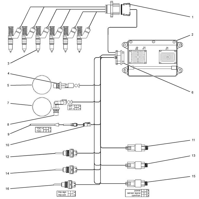
Illustration 4
Block diagram for the 2506-15 engine components
(1) 12 Pin Connector (9) Timing Calibration Probe
(2) Electronic Control Module (ECM) (10) Timing Calibration Probe Connector
(3) Electronic Unit Injectors (11) Atmospheric Pressure Sensor
(4) Crankshaft Position Sensor (12) Inlet Manifold Temperature Sensor
(5) 36 - 1 Tooth Gear (13) Inlet Manifold Pressure Sensor
(6) 120 Pin Connector (14) Coolant Temperature Sensor
(7) 36 + 1 Tooth Gear (15) Engine Oil Press ure Sensor
(8) Camshaft Position Sensor (16) Fuel Temperature Sensor
g01278058
This document has been printed from SPI². Not for Resale
![]()
![]()
![]() 16
16
Troubleshooting Section
KENR6224
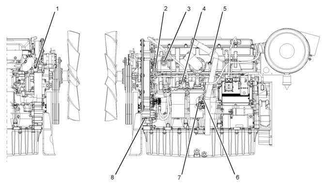
Illustration 5
Locations of the sensors on the 2506-15 engine
(1) Coolant temperature sensor
(2) Camshaft position sensor
(3) Inlet manifold pressure sensor
(4) Fuel temperature sensor
(5) Inlet manifold temperature sensor
(6) Engine oil pres sure sensor
(7) Atmospheric pressure sensor
(8) Crank shaft position sensor
g01279372
This document has been printed from SPI². Not for Resale
![]()
![]()
![]() KENR6224
KENR6224
17
Troubleshooting Section
Illustration 6
Block diagram for the machine components
g01278305
This document has been printed from SPI². Not for Resale
| |||||||||||||||||||||||||||||||||
Troubleshooting Section
KENR6224
Engine Wiring
Information
i02548945
1.
2.
Stop the engine. Turn the keyswitch to the OFF
position.
Disconnect the negative battery cable from the
battery. If a battery disconnect switc h is installed,
open the switch.
The wiring schematics are revised periodically.
The wiring schematics will change as updates are
made to the machine harness. For the most current
information, always check the revision number of the
schematic. Use the schematic with the latest revision
number.
Harness Wire Identification
Perkins identifies all wires with eleven solid c olors.
The circuit number is stamped on the wire at a 25 mm
(1 inch) spacing. Table 4 lists the wire colors and the
color codes.
Table 4
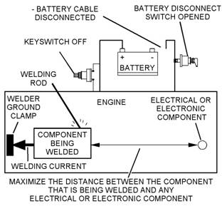
Illustration 7
Service welding guide (typical diagram)
g01143634
Welding on a Machine that is Equipped
with an Electronic Control System ( ECM)
Proper welding procedures are necessary in order
to avoid damage to the engine’s electronic c ontrol
module, sensors, and associated components. The
component that requires welding should be removed.
When welding on a machine that is equipped with an
ECM and removal of the component is not possible,
the following procedure must be followed. This
procedure provides the minimum amount of risk to
the electronic components.
NOTICE
Do not ground the welder to electrical components
such as the ECM or sensors. Improper grounding can
cause damage to the drive train bearings, hydraulic
components, electrical components, and other com-
ponents.
Clamp the ground cable from the welder to the com-
ponent that will be welded. Plac e the clamp as close
as possible to the weld. This will help reduce the pos-
sibility of damage.
3.
4.
5.
Connect the welding ground cable as close
as possible to the area that will be welded.
Components which may be damaged by welding
inc lude bearings, hydraulic components, and
electrical/electronic components.
Protect the wiring harness from welding debris
and from spatter.
Weld the materials by using standard welding
methods.
This document has been printed from SPI². Not for Resale
![]()
![]()
![]() KENR6224
KENR6224
19
Troubleshooting Section
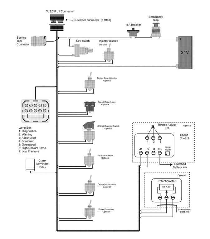
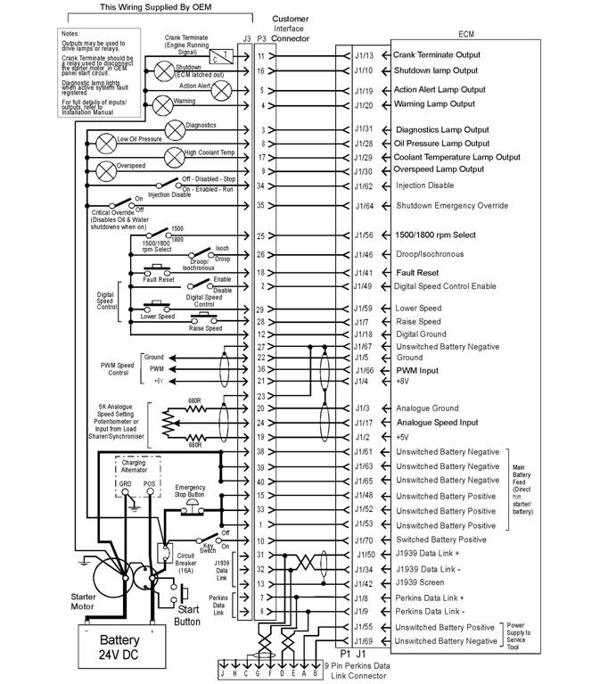
Illustration 8
Schematic diagram for a machine with an OEM connector
g01275859
This document has been printed from SPI². Not for Resale
![]()
![]()
![]() 20
20
Troubleshooting Section
KENR6224
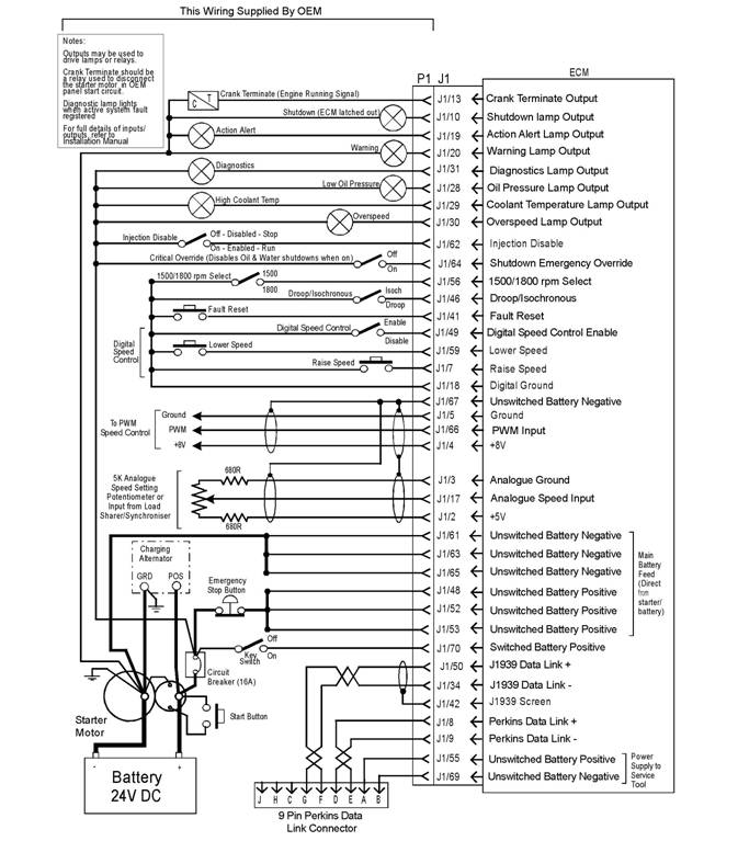
Illustration 9
Schematic diagram for a machine without an OEM connector
g01275860
This document has been printed from SPI². Not for Resale
![]()
![]() KENR6224
KENR6224
21
Troubleshooting Section
Programming
Par ame ters
i02549443
Since factory passwords contain alphabetic
characters, the Perkins Electronic Service Tool
(EST) must be used to perform these functions. In
order to obtain factory passwords, proceed as if you
already have the pass word. If factory passwords are
Programming Parameters
The Perkins Electronic Service Tool (EST) can be
used to view certain parameters that can affect
the operation of the engine. The Perkins EST can
also be used to change certain parameters. The
parameters are stored in the Electronic Control
Module (ECM). Some of the parameters are
protected from unauthoriz ed changes by passwords.
Parameters that can be changed have a tattletale
number. The tattletale number shows if a parameter
has been changed.
i02549444
Factory Passwords
needed, the Perkins EST will request the factory
pas swords and the Perkins EST will display the
information that is required to obtain the passwords.
For the worksheet that is used for acquiring factory
passwords, refer to programming parameters
Troubleshooting, “Factory Passwords Worksheet”.
i02549455
Factory Passwords Worksheet
Note: A mistake in recording these parameters will
result in incorrect passwords.
NOTICE
Operating the engine with a flash file not des igned for
that engine will damage the engine. Be sure the flash
file is correct for your engine.
Note: Factory passwords are provided only to
Perkins dealers and distributors.
Factory passwords are required to perform each of
the following functions:
• Program a new Electronic Control Module (ECM).
When an ECM is replaced, the system
configuration parameters must be programmed
into the new ECM. A new ECM will allow these
parameters to be programmed once without factory
pas swords. After the initial programming, some
parameters are protected by factory passwords.
• Clear event codes.
Most event codes require the use of factory
pas swords to clear the code once the code has
been logged. Clear these codes only when you are
certain that the fault has been corrected.
• Unlock parameters.
Factory passwords are required in order to unlock
certain system configuration parameters. Refer
to Troubleshooting, “System Configuration
Parameters”.
This document has been printed from SPI². Not for Resale

![]() 22
22
Troubleshooting Section
KENR6224
Table 5
Factory Passwords Worksheet
Note: If you do not have the part number for the flash
file, us e “PTMI” on the Perkins Internet.
Dealer Code
Customer ’s Name
Address
Telephone Number
Information From the Engine Information Plate
Engine Serial Number
Full Load Setting
Full Torque Setting
Information From the Diagnostic Clock
Engine Hours
Information From the “Factory Password Entry
Screen” on the Electronic Service Tool
Electronic Service Tool
Serial Number
Engine Serial Number
ECM Serial Number
Total Tattletale
Reason Code
From Interlock(1)
To Interlock(1)
Fact ory Passwords
Factory Password (No. 1)
Factory Password (No. 2)
(1) This parameter is required when the engine is being rerated.
This parameter is displayed only when the engine is being
rerated.
i02549457
Flash Programming
Flash Programming – A method of loading a flash
file into the Electronic Control Module (ECM)
The electronic service tool can be utilized to
flash program a flash file into the ECM. The flash
programming transfers the flash file from the PC to
the ECM.
Flash Programming a Flash File
1. Obtain the part number for the new flash file.
Note: You must have the engine serial number in
order to search for the part number for the flash file.
2. Connect the electronic service tool to the service
tool connector.
3. Turn the keyswitch to the ON position. Do not start
the engine.
4. Select “WinFlash” from the “Utilities” menu on the
electronic service tool.
Note: If “WinFlash” will not communicate with the
ECM, refer to Troubleshooting, “Electronic Service
Tool Will Not Communicate with ECM”.
5. Flash program the flash file into the ECM.
a. Select the engine ECM under the “Detected
ECMs”.
b. Press the “Browse” button in order to select
the part number of the flash file that will be
programmed into the ECM.
c. When the correct flash file is selected, press
the “Open” button.
d. Verify that the “File Values” match the
application. If the “File Values” do not match
the application, search for the correct flash file.
e. When the correct flash file is selected, press
the “Begin Flash” button.
f. The electronic service tool will indicate when
flash programming has been successfully
completed.
6. Start the engine and check for proper operation.
a. If a diagnostic code 0268-02 is generated,
program any parameters that were not in the
old flash file.
b. Access the “Configuration” screen under
the “Service” menu in order to determine
the parameters that require programming.
Look under the “Tattletale” column. All of the
parameters should have a tattletale of 1 or
more. If a parameter has a tattletale of 0,
program that parameter.
This document has been printed from SPI². Not for Resale
![]() KENR6224
KENR6224
23
Troubleshooting Section
“WinFlash” Error Messages
If you receive any error messages during flash
programming, click on the “Cancel” button in order
to stop the process. Access the information about
the “ECM Summary” under the “Information” menu.
Ensure that you are programming the correct flash
file for your engine.
i02549465
Injector Trim File
The electronic service tool is used to load the injector
trim files into the Electronic Control Module (ECM).
The injector trim files must be loaded into the ECM if
5.
6.
7.
8.
9.
Connect the electronic service tool to the
service tool connector. Refer to Troubleshooting,
“Electronic Service Tools”.
Turn the keyswitch to the ON position.
Select the following menu options on the electronic
service tool:
• Service
• Calibrations
• Injector Trim Calibration
Select the appropriate cylinder.
Click on the “Change” button.
|
|
• An injector is replaced.
• The ECM is replaced.
• Diagnostic code 0253-02 is active.
• Injectors are exchanged between cylinders.
Exchanging Electronic Unit Injectors
Exchanging injectors can help determine if a fault is
in the injector or in the cylinder. If two injectors that
are currently installed in the engine are exchanged
between cylinders, the injector trim files can also
be exchanged. Press the “Exchange” button at the
bottom of the “Injector Trim Calibration” screen on
the electronic service tool. Select the two injectors
that will be exchanged and press the “OK” button.
The tattletale for the injectors that were exchanged
will increase by one.
Note: The serial number for the injector and the
confirmation code number for the injector are located
on the injector.
1. Record the serial number and the confirmation
code numberfor each injector.
2. Obtain the injector trim file by one of the following
methods:
Internet.
replacement injector.
3. Enter the serial number for the injector in the
search field.
4. Download the injec tor trim file to the PC. Repeat
this procedure for each injector, as required.
10. Select the appropriate injector trim file from the
PC.
11. Click on the “Open” button.
12. If you are prompted by the electronic service
tool, enter the confirmation code number for the
injector into the field.
13. Click on the “OK” button.
The injector trim file is loaded into the ECM.
14. Repeat the procedure for each cylinder, as
required.
This document has been printed from SPI². Not for Resale
![]() 24
24
Troubleshooting Section
KENR6224
System
Conf iguration
ECM Serial Number
This is a read only parameter that displays the serial
Parameters
System Configuration
Parameters
i02549472
number of the ECM.
ECM Software Release Date
This parameter is defined by the ECM software
and this parameter is not programmable. The ECM
software release date is used to provide the version
of the software. The customer parameters and the
software change levels can be monitored by this
System configuration parameters affect the emissions
of the engine or the power of the engine. System
configuration parameters are programmed at the
factory. Normally, system configuration parameters
would never need to be changed through the life of
the engine. System configuration parameters must
be reprogrammed if an Electronic Control Module
(ECM) is replaced. System configuration parameters
do not need to be reprogrammed if the ECM software
is changed. The correct values for these parameters
are stamped on the engine information ratings plate.
Factory passwords are required to change these
parameters. The following information is a description
of the system configuration parameters.
Full Load Setting (FLS)
The full load setting is a number that represents
the adjustment to the fuel system that was made
at the factory in order to fine tune the fuel sy stem.
The correct value for this parameter is stamped on
the engine information ratings plate. If the ECM is
replaced, the full load setting mus t be reprogrammed
in order to prevent a 0268-02 diagnostic code from
becoming active.
Full Torque Setting (FTS)
Full torque setting is similar to full load setting. If
the ECM is replaced, the full torque setting must
be reprogrammed in order to prevent a 0268-02
diagnostic code from becoming active.
Software Part number
This is the part number of the software that is flashed
into the ECM.
Engine Serial Number
When a new ECM is deliv ered, the engine serial
number in the ECM is not programmed. The engine
serial number should be programmed to matc h the
engine serial number that is stamped on the engine
information plate.
date. The date is provided in the month and the year
(AUG06). AUG is the month (August). 06 is the year
(2006).
Critical Override Switch
If equipped, the critical override switch allows the
engine to continue running even if engine oil pressure
or coolant temperature have reached the shutdown
limit for the engine. If the engine is run in this
condition, the engine warranty is canc elled and any
events that occur are s tored in the ECM with the time
and the date. Implementation of this facility requires
a fac tory password.
Total Tattletale
This parameter displays the total number of changes
that have been made to the configuration parameters.
This document has been printed from SPI². Not for Resale