 English
 Espaol
 Franais
 阿拉伯
阿拉伯 中文
中文 Deutsch
 Italiano
 Português
 日本
日本 韩国
韩国 български
 hrvatski
 esky
esky Dansk
Dansk Nederlands
 suomi
suomi Ελληνικ
 印度
印度 norsk
norsk Polski
 Roman
Roman русский
 Svenska
Perkins2306柴油发动机威尔逊P550柴油发电机配件KRP1718水泵供应商,Perkins2306柴油发动机威尔逊P550柴油发电机配件KRP1718水泵技术价格规格咨询服务,Perkins2306柴油发动机威尔逊P550柴油发电机配件KRP1718水泵零配件供应,Perkins2306柴油发动机威尔逊P550柴油发电机配件KRP1718水泵售后服务中心,Perkins2306柴油发动机威尔逊P550柴油发电机配件KRP1718水泵,Perkins2306柴油发动机威尔逊P550柴油发电机配件KRP1718水泵详细的技术参数,

产品中心
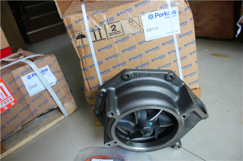
Perkins2306柴油发动机威尔逊P550柴油发电机配件KRP1718水泵
详细描述
项目 零配件号码 新件号 描述
1 KRP1718 1 KRP1718 水泵装备
1 KRP1553 1 KRP1718 水泵装备
20 CH10542 1 CH10542 承接器
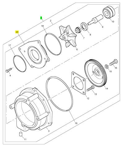
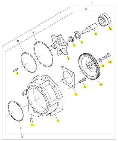
项目 零配件号码 新件号 描述
2 1 水泵
17 CH10544 1 CH10544 密封O型圈
18 CH10543 1 CH10543 密封O型圈
19 CH10545 1 CH10545 密封O型圈
项目 零配件号码 新件号 描述
3 1 水泵壳
4 CH10550 1 CH10550 螺拴
5 CH10549 1 CH10549 垫圈
6 CH10548 1 CH10548 动叶轮
7 CH12889 1 CH12889 密封垫 - 水泵
8 CH10554 1 CH10554 密封垫 - 水泵
9 CH10555 1 CH10555 轴
10 CH10558 1 CH10558 辊轴承
11 CH10560 1 CH10560 过滤器
12 CH10559 1 CH10559 保有板
13 CH10557 4 CH10557 螺拴
14 CH10553 1 CH10553 水泵传动机构
15 CH10556 1 CH10556 垫圈
16 CH10551 1 CH10551 螺拴
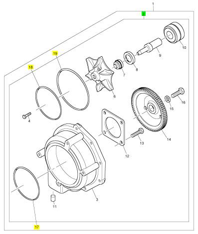
项目 零配件号码 新件号 描述
2 1 水泵
17 CH10544 1 CH10544 密封O型圈
18 CH10543 1 CH10543 密封O型圈
19 CH10545 1 CH10545 密封O型圈
项目 零配件号码 新件号 描述
3 1 水泵壳
4 CH10550 1 CH10550 螺拴
5 CH10549 1 CH10549 垫圈
6 CH10548 1 CH10548 动叶轮
7 CH10552 1 CH12889 密封垫 - 水泵
8 CH10554 1 CH10554 密封垫 - 水泵
9 CH10555 1 CH10555 轴
10 CH10558 1 CH10558 辊轴承
11 CH10560 1 CH10560 过滤器
12 CH10559 1 CH10559 保有板
13 CH10557 4 CH10557 螺拴
14 CH10553 1 CH10553 水泵传动机构
15 CH10556 1 CH10556 垫圈
16 CH10551 1 CH10551 螺拴
项目 零配件号码 新件号 描述
1 CH11034 1 CH11034 交流充电发电机托架
2 ST29054 1 ST29054 CAPSCREW
3 ST15905 1 ST15905 垫圈
项目 零配件号码 新件号 描述
1 CH11087 1 CH11087 交流充电发电机
(1) CH11087 1 CH11087 交换交流充电发电机
项目 零配件号码 新件号 描述
1 CH11218 1 CH11218 涡轮增压器
1 P/CH11218 1 CH11218 涡轮增压器
1 CH11218 1 CH11218 涡轮增压器
(1) P/CH11218 1 CH11218 涡轮增压器
(1) CH11218 1 CH11218 涡轮增压器
2 CH11471 1 CH11471 密封垫 -涡轮增压器
2 CH10014 1 CH11471 密封垫 -涡轮增压器
3 CH10733 4 CH10733 螺拴
4 CH10734 4 CH10734 锁紧螺母
Configuration Parameters
Table 6
|
Screen Order |
Configuration Parameter Description |
Read/Write Security |
|
1 |
Selected Engine Rating |
|
|
2 |
Rating Number |
RW2(1) |
|
3 |
Rated Frequency |
R(2) |
|
4 |
Rated Genset Speed |
R(2) |
|
5 |
Rated Real Genset Power |
R(2) |
|
6 |
Rated Apparent Genset Power |
R(2) |
|
7 |
Engine Rating Application Type |
R(2) |
|
8 |
External Speed Selection Switch Installed |
RW2(1) |
|
9 |
ECM Identification Parameters |
|
|
10 |
Equipment ID |
RW2(1) |
|
11 |
Engine Serial Number |
RW3(3) |
|
12 |
ECM Serial Number |
R(2) |
|
13 |
ECM Software Part Number |
R(2) |
|
14 |
ECM Software Release Date |
R(2) |
|
15 |
ECM Software Description |
R(2) |
|
16 |
Security Access Parameters |
|
|
17 |
Total Tattl etale |
R(2) |
|
18 |
Engine/Gear Parameters |
|
|
19 |
Engine Acceleration Rate |
RW2(1) |
|
20 |
Droop/Isochronous Switch Installed. |
RW2(1) |
|
21 |
Droop/Isochronous Selection |
RW2(1) |
|
22 |
Engine Speed Droop |
RW2(1) |
|
23 |
Critical Override Switch Installed |
RW2(1) |
|
24 |
Digital Speed Control Installed |
RW2(1) |
|
25 |
Speed Control Minimum Speed |
RW2(1) |
|
26 |
Speed Control Maximum Speed |
RW2(1) |
|
27 |
Digital Speed Control Ramp Rate |
RW2(1) |
|
28 |
Crank Terminate Speed |
RW2(1) |
|
29 |
I/O Configuration Parameters |
|
|
30 |
Desired Speed Input Arrangement |
RW2(1) |
|
31 |
Fuel Enable Input Configurati on |
RW2(1) |
|
32 |
System Parameters |
|
|
33 |
Full Load Setting (FLS) |
RW3(3) |
|
34 |
Full Torque Setting (FTS) |
RW3(3) |
|
35 |
Governor Gain Factor |
RW1(4) |
|
36 |
Governor Minimum Stability Factor |
RW1(4) |
|
37 |
Governor Maximum Stability Factor |
RW1(4) |
(continued)
This document has been printed from SPI². Not for Resale
![]() 26
26
Troubleshooting Section
KENR6224
(Table 6, contd)
|
38 |
Passwords |
|
|
39 |
Customer Password 1 |
RW2(1) |
|
40 |
Customer Password 2 |
RW2(1) |
(1)
(2)
(3)
(4)
Read/write with a customer password
Read only
Read/write with a factory password
Read/write without a password
Customer Specified Parameters
Customer specified parameters allow the engine to
be configured to the exact needs of the application.
Customer parameters may be changed repeatedly as
a customer’s operation changes.
The following information is a brief desc ription of the
customer specified parameters.
Rating Duty Selection
This parameter enables selection of the engine rating
from a series of maps within the ECM. Changing the
rating requires a cus tomer password. The available
ratings within the ECM will vary with the type of
engine and the specification of the engine.
Rated Frequency
This parameter displays the rated frequency of the
genset. This is determined by the rating selection
and the status of the external speed selection s witch.
This parameter is read only.
Rated Speed
This parameter displays the rated speed of the
engine. This is determined by the rating selection
and the status of the external speed selection s witch.
This parameter is read only.
Rated Real Genset Power
This parameter displays the maximum power in kW
of the currently s elected rating. This parameter is
read only.
Rated Apparent Genset Power
This parameter displays the maximum power in kVA
of the currently s elected rating. This parameter is
read only.
Rating Configuration
This parameter displays the configuration of the
currently selected rating. The following list gives the
possible configurations:
• Standby power
• Limited time prime power
• Prime power
• Continuous or baseload power
For definitions of these ratings, refer to ISO8528.
This parameter is read only.
Note: Not all of the above rating configurations will
be available in the software files of every ECM.
E xternal Speed Selection Switch Enable
For dual s peed applications with an external
speed selection switch, this parameter enables the
functionality of the speed selection switch within
the s oftware. Changing this parameter requires a
customer password.
Engine Startup Acceleration Rate
This parameter enables the ac celeration rate of
the engine in RPM per second to be programmed.
The parameter can be programmed from idle speed
to rated speed. Control of this parameter enables
any overshoot in speed on start-up to be limited.
Changing this parameter requires a c ustomer
pas sword.
Droop/Isochronous Switch Enable
This parameter determines whether the external
droop/isochronous switch is enabled or disabled.
Changing this parameter requires a c ustomer
pas sword.
This document has been printed from SPI². Not for Resale
![]() KENR6224
KENR6224
27
Troubleshooting Section
Droop/Isochronous Selection
The engine will normally be run in isochronous mode.
This means that the engine speed will not change,
regardless of the load. If the engine needs to operate
in parallel with another genset or the engine needs
to operate in parallel with the grid, it is nec essary to
operate the engine in droop mode in order to ensure
the stability of the system. This parameter enables
droop/isochronous running selection. Changing this
parameter requires a customer pass word.
Note: If an external droop/isochronous switch is
enabled, the position of this switch will override the
“Droop/Is ochronous” selection.
Engine Speed Droop
If droop operation is selected, this parameter
allows the setting of percentage droop. This is the
percentage of speed reduction with an increase in
load. This parameter has no effect when the engine
is running in isochronous mode. Changing this
parameter requires a customer pass word.
Digital Speed Cont rol Installed
This parameter determines whether input from the
raise/lower switch controls the speed of the engine.
If digital speed control is not installed, the speed of
the engine is controlled by inputs from the analog
throttle or the PWM throttle. This depends on the
input that is selected in the desired speed input
configuration. Changing this parameter requires a
customer password.
Digital S peed Control Minimum Speed
This setting determines the minimum speed range of
both the raise/lower control and the analog control.
For example, if this is set to 100 RPM and the
nominal engine speed is s elected to 1500 RPM, the
minimum speed setting is 1400 RPM. This parameter
does not affect the range of the PWM speed control
as this control has a fixed minimum limit and a fixed
maximum limit. Changing this parameter requires a
customer password.
Digital S peed Control Maximum Speed
This setting determines the maximum speed range of
both the raise/lower control and the analog control. If
this is set to 100 RPM and the nominal engine speed
is selected to 1500 RPM, the maximum speed setting
is 1600 RPM. This setting does not affect the range
of the PWM speed control as this c ontrol has a fixed
minimum limit and a fixed maximum limit. Changing
this parameter requires a customer password.
Digital Speed Control Ramp Rate
This setting determines the rate of change of engine
speed in RPM when the raise/lower switch inputs are
closed. Changing this parameter requires a customer
pas sword.
Crank Terminate Speed
This parameter is used to set the engine speed that
is required before the output from the crank terminate
relay is switched. Changing this parameter requires a
customer password.
Desired Speed Input Arrangement
If a digital speed control is not installed, this
parameter enables selection of either an analog
throttle, a PWM throttle or an ex ternal CAN Bus
speed control. The inputs from the analog throttle,
the PWM throttle or the CAN Bus speed control
are normally used with genset load sharing and
synchronizing controllers. Changing this parameter
requires a customer password.
Note: If a PWM throttle, an analog throttle or a CAN
Bus speed control is selected but there are no inputs
to the terminals for the selected speed control, the
engine will default to running at 1100 RPM.
If a PWM throttle, an analog throttle or a CAN Bus
speed control is not used, the digital s peed control
should be selected.
Fuel Enable Input Configuration
This parameter enables the selection of switch to
battery positive or CAN input for the control of the
injector On and injector Off.
Governor Gain Parameters
The following items are the adjustable parameters for
gov ernor gain:
• Governor Gain Factor
• Governor Minimum Stability Factor
• Governor Maximum Stability
Note: No engineering units are associated with these
numbers.
Note: The programmable range is wide for flexibility.
Values of 1 to 40000 are valid. The full range of this
parameter may not be used on any system. Do not
expect to use the whole range.
This document has been printed from SPI². Not for Resale
![]()
![]() 28
28
Troubleshooting Section
KENR6224
|
|
Governor Gain Factor
The governor gain factor is multiplied to the difference
between desired speed and actual speed.
large, the engine speed can overshoot the desired
speed. The overshoot is caused by an excessive
correction or an instability of a steady state.
that is nec essary to accelerate the engine to the
des ired speed must be obtained by increas ing the
stability terms to a higher value. As this process is
slow, the response of the engine speed is slow.
Governor Minimum/Maximum Stability
Factor
The stability factor terms work in order to eliminate a
steady state speed error. There are two gain terms
that are used for stability. If the error is greater than
20 RPM and if the error is increasing, the maximum
stability gain is functioning. If the error is less than
20 RPM, the minimum stability gain is used. This
function allows the use of a high gain that would
2.
3.
4.
5.
6.
Start the engine. On the engine mounted genset
control panel, check that the engine has reached
rated speed. This panel will serve as the reference
point for the speed during this procedure.
Enter the “Configuration Parameters” screen on
the electronic service tool.
Determine the desired scenario in order to tune
the engine. For example, check if the engine has
poor response during specific load assignments
or specific load dumps.
Perform the desired load change that is detailed
in step 4. Check the response of the engine by
viewing the following parameters.
• The engine speed on the control panel on the
genset
• The frequency response of the system bus to
the load change
• Listening to the response of the engine
Use the listed suggestions in order to determine
the gains that require adjustment.
|
|
engine is operating near the desired speed.
stability gain is set too high, the governor will
provide more fuel than the amount that is
nec essary to bring the error to zero. The additional
fuel will cause the engine speed to overshoot and
the engine to produce excessive combustion noise.
stability gain is set too low, excessive time is taken
in order to stabilize the engine s peed.
Tuning Procedure
1. Turn the keyswitch to the OFF/RESET position.
Before the tuning procedure is started, connect
the electronic serv ice tool and then check
that engine overspeed protection is enabled.
Engine overspeed is configured on the
“Service\Monitoring System” sc reen on the
electronic service tool.
NOTICE
Performing engine governor tuning without engine
overspeed protection could result in serious engine
damage. Ens ure that this parameter is ON while
performing this proc edure.
Note: Usually, the gain factor of the governor should
be lower than the minimum stability fac tor of the
gov ernor in order to obtain optimum performance.
The maximum stability factor is typically a smaller
value than the minimum stability gain and the
gov ernor gain factor.
7. Repeat steps 5, 6 and 7 until a desired engine
response can be met. Use large adjustments
(10% of original gain) initially to generally tune the
engine in the proper manner. As the response
gets closer to the desired value, increase the
gains in smaller increments (1% of total gain).
Customer Password 1, Customer
Password 2
Customer passwords are the programmable
parameters that can be used to protect certain
configuration parameters from any unauthorized
changes.
Engine monitoring
Perkins provides an engine monitoring system that
is ins talled at the factory. The system monitors the
following parameters:
• Engine oil pressure
• Coolant temperature
This document has been printed from SPI². Not for Resale
![]() KENR6224
KENR6224
29
Troubleshooting Section
•
•
•
•
Intake manifold air temperature
Engine speed
Boost pressure
Fuel temperature
Diagnostic codes that are stored in memory are
called Logged diagnostic codes. The fault may have
been temporary or the fault may hav e been repaired
since the fault was logged. For this reason, logged
codes do not necessarily mean that something needs
to be repaired. Logged diagnostic codes are meant
to be an indication of probable causes for intermittent
faults.
The monitoring system has three levels of operation.
The levels are described below.
Warning Operation
In the Warning condition, the ECM causes the
warning lamp to come ON. The warning lamp
indicates that a fault has been detected by the engine
monitoring system. No further action by the ECM or
the engine occurs.
Action Alert Operation
In the Action Alert condition, the ECM causes the
action alert lamp to come on. The Action Alert lamp
indicates that a fault has been detected by the engine
monitoring system. This condition is normally wired
in order to cause a shutdown and the shutdown is
controlled by the control panel on the mac hine.
Shutdown Operation
If the fault reaches the Shutdown c ondition, the ECM
causes the shutdown lamp to come on. Unless the
engine is in a Critical Override condition, the engine
will shut down.
Monitoring the Fuel Temperature
The fuel temperature sensor monitors the fuel
temperature. The signal from the sensor allows
the ECM to compensate for changes in the fuel
temperature by adjusting the fuel rate for constant
power.
The sensor is also used to warn the operator of
exces sive fuel temperature with a diagnostic event
code. Excessive fuel temperatures can adversely
affect engine performance.
Self-Diagnostics
The electronic system has the ability to diagnose
faults. When a fault is detected, a diagnostic code
is generated and the diagnostic code is stored
in permanent memory (logged) in the ECM. The
diagnostic lamp is also activated.
When diagnostic codes occur, the diagnostic codes
are referred to as Active diagnostic codes. Active
diagnostic c odes indicate that a fault of some kind
currently exists.
Diagnostic codes that identify operating conditions
outside the normal operating range are called Events.
Event codes are not typically an indication of a fault
with the electronic system.
Note: Some of the diagnostic codes require
pas swords to clear the code.
Effect of Diagnostic Codes on
Engine Performance
The diagnostic lamp comes on when a specific
condition exists. When the ECM detects an engine
fault, the ECM generates an active diagnostic code
and the diagnostic code is logged. The diagnostic
code is logged in order to record the following
information:
• The date
• The time
• The number of occurrences of the fault
The two types of diagnostic codes are Fault codes
and Event codes.
Fault Codes
Fault codes are provided in order to indicate that
an electrical fault or an electronic fault has been
detected by the ECM. In some cases, the engine
performance can be affected by the condition that is
causing the code. More frequently, there is no effect
on engine performance.
Event Codes
Event codes are used to indicate that some
operational fault has been detected in the engine by
the ECM. This does not usually indicate an electronic
malfunction.
The ECM also provides a cloc k in order to add the
date and the time to the following critical event codes:
• 360-3 Low oil pressure shutdown
• 361-3 High coolant temperature shutdown
This document has been printed from SPI². Not for Resale

![]() 30
30
Troubleshooting Section
KENR6224
Refer to the Troubleshooting Guide, “Diagnostic
Code Cross Reference” for a list of all the diagnostic
fault codes.
Settings for the Monitoring System
Table 7
Parameter
Low Engine Oil Pressure
Warn Operator (1)
On
State
Trip Point
300 kPa (43.5 psi)
Delay Time
60 seconds
Action Alert (2)
Engine Shutdown (3)
High Engine Coolant Temperature
Warn Operator (1)
Action Alert (2)
Engine Shutdown (3)
Engine Overspeed
Warn Operator (1)
Action Alert (2)
Engine Shutdown (3)
High Intake Manifold Air Temperature
Warn Operator (1)
Action Alert (2)
High Fuel Supply Temperature
Warn Operator (1)
Action Alert (2)
High Boost Pressure
Warn Operator (1)
Action Alert (2)
Always On
Always On
On
Always On
Always On
On
Always On
Always On
On
Always On
On
Always On
On
Always On
None
None
104 °C (2190 °F)
105 °C (221 °F)
108 °C (226 °F)
2000 RPM
2050 RPM
2140 RPM
75 °C (167 °F)
78 °C (172 °F)
60 °C (140 °F)
68 °C (154 °F)
300 kPa (43.5 psi)
None
2 seconds
2 seconds
60 seconds
10 seconds
10 seconds
1 second
1 second
0 second
60 seconds
10 seconds
60 seconds
60 seconds
30 seconds
5 seconds
This document has been printed from SPI². Not for Resale
![]() KENR6224
KENR6224
31
Troubleshooting Section
Troubleshoot ing
Diagnosti c Code
without
a
Alternator Will Not Charge
i02556542
Alternator Noise
Note: This is not an electronic system fault.
i02556541
Note: This is not an electronic system fault.
Probable Causes
• Alternator drive belt
• Charging circuit
Refer to Testing and Adjusting for information on
possible electrical causes of this condition.
Probable Causes
•
Alternator
•
•
•
•
Alternator drive belt
Alternator mounting bracket
Alternator drive pulley
Alternator bearings
Recommended Actions
Alternator Drive Belt
Inspect the condition of the alternator drive belt. If
the alternator drive belt is worn or damaged, chec k
that the drive belt for the alternator and the pulley are
correctly aligned. If the alignment is correct, replace
the drive belt. Refer to Systems Operation, Testing
and Adjusting, “Belt Tension Chart”.
Recommended Actions
Alternator Drive Belt
Inspect the condition of the alternator drive belt. If
the alternator drive belt is worn or damaged, check
that the drive belt for the alternator and the pulley are
correctly aligned. If the alignment is correct, replace
the drive belt. Refer to Disassembly and Assembly,
“Alternator Belt - Remove and Install”.
Alternator Mounting Bracket
Inspect the alternator mounting bracket for cracks
and wear. Repair the mounting bracket or replace
the mounting bracket in order to ensure that the
alternator drive belt and the alternator drive pulley
are in alignment.
Alternator Drive Pulley
Remove the nut for the alternator drive pulley and
then inspect the nut and the drive shaft. If no damage
is found, install the nut and tighten the nut to the
correct torque. Refer to Specifications, “Alternator
and Regulator” for the correct torque.
Alternator Bearings
Check for excessive play of the shaft in the alternator.
Check for wear in the alternator bearings. The
alternator is a nonserviceable item. The alternator
must be replaced if the bearings are worn. Refer to
Disassembly and Assembly, “Alternator - Remove”
and Disassembly and Assembly , “Alternator - Install”.
Charging Circuit
Inspect the battery cables, wiring, and connections in
the charging circuit. Clean all connections and tighten
all connections. Replac e any faulty parts.
Alternator
Verify that the alternator is operating correctly.
Refer to Systems Operation, Testing and Adjusting,
“Charging System - Test”. The alternator is not a
serviceable item. The alternator must be replaced
if the alternator is not operating correctly. Refer to
Disassembly and Assembly, “Alternator - Remove
and Install”.
i02556551
Battery
Note: This is not an electronic system fault.
Probable Causes
• Charging circuit
• Battery
• Auxiliary dev ice
This document has been printed from SPI². Not for Resale
![]()
![]()
![]() 32
32
Troubleshooting Section
KENR6224
Recommended Actions
Charging Circuit
If a fault in the battery charging c ircuit is suspected,
refer to Troubleshooting, “Alternator Will Not Charge”.
Battery
1. Check that the battery is able to maintain a charge.
•
•
•
•
•
Rated fuel position and/or FRC fuel position
Inlet manifold pressure sensor
Fuel supply
Air inlet and exhaust system
Accessory equipment
2.
Refer to Testing and Adjusting, “Battery - Test”.
If the battery does not maintain a charge,
replace the battery. Refer to the Operation and
Maintenance Manual, “Battery - Replace”.
Recommended Actions
Diagnostic Codes and Event Codes
Certain diagnostic codes and/or event codes may
cause poor performance. Connect the electronic
service tool and then check for active codes and
Auxiliary Device
1. Check that an auxiliary device has drained the
battery by being left in the ON position.
2. Charge the battery.
3. Verify that the battery is able to maintain a charge
when all auxiliary devices are switched off.
i02556559
Can Not Reach Top Engine
RPM
Note: If this fault occurs only under load, refer to
the Troubleshooting Guide, “Low Power/Poor or No
Response to Throttle”.
The connection of any electrical equipment and
the disconnection of any electrical equipment may
cause an explosion hazard which may result in in-
jury or death. Do not connect any electrical equip-
ment or disconnect any electrical equipment in an
explosive atmosphere.
Probable Causes
• Diagnostic codes
• Event codes
• Programmable parameters
• Cold mode
• Throttle signal
logged codes. Troubleshoot any codes that are
present before continuing with this procedure.
Programmable Parameters
Check the following parameters on the electronic
service tool:
• “Des ired Engine Speed”
• “Desired Speed Input Configuration”
Determine the type of speed control that is used in
the applic ation. Program the parameters to match
the type of speed control that is used. Refer to the
Troubleshooting Guide, “Speed Control Circuit - Test”
for more information.
Note: The engine will have poor performance if the
parameters are not programmed correctly.
Cold Mode
Use the electronic service tool to verify that the
engine has exited cold mode. A status flag will
appear if the engine is operating in cold mode. This
may limit engine speed.
Throttle Signal
Connect the electronic service tool to the diagnostic
connector. View the status for the “Desired Engine
Speed” on the status screen. Operate the speed
control from the Low Speed position to the High
Speed position. If the status cannot operate in the full
range, refer to the Troubleshooting Guide, “Speed
control - Calibrate”.
This document has been printed from SPI². Not for Resale
![]() KENR6224
KENR6224
33
Troubleshooting Section
Diagnostic codes that are related to the J1939 data
link will prevent correct operation of the throttle if the
throttle position is transmitted over the data link. If
there is a fault in the data link, the engine will remain
at low idle until the data link is repaired.
Inlet Manifold Pressure Sensor, Rated
Fuel Position and/or FRC Fuel Position
1. With the engine at full load, monitor “Fuel Position”
and “Rated Fuel Limit” on the status screen. If
“Fuel Position” does not equal “Rated Fuel Limit”
then check air inlet manifold pressure.
2. Verify that there are no active diagnostic codes
that are associated with the inlet manifold pressure
sensor or with the atmospheric pressure sensor.
3. Monitor the inlet manifold pressure and the
atmospheric pressure on the status screen for
normal operation.
Fuel Supply
1. Check the fuel lines for the following faults:
restrictions, collapsed lines, and pinched lines. If
faults are found with the fuel lines, repair the lines
and/or replace the lines.
2. Check the fuel tank for foreign objects which may
block the fuel supply.
3. Prime the fuel system if any of the following
procedures have been performed:
• Replacement of the fuel filters
• Service on the low pressure fuel supply circuit
• Replacement of electronic unit injectors
Note: A sight glass in the low pressure supply line is
helpful in diagnosing air in the fuel. Refer to Systems
Operation, Testing and Adjusting.
4. Cold weather adversely affects the characteristics
of the fuel. Refer to the Operation and
Maintenance Manual for information on improving
the c haracteristics of the fuel during cold weather
operation.
5. Check the fuel pressure during engine cranking.
Check the fuel pressure on the outlet side of
the fuel filter. Refer to Specifications for correct
pressure values. If the fuel pressure is low,
replace the fuel filters. If the fuel pressure is still
low, check the following items: fuel transfer pump,
fuel transfer pump coupling, and fuel pressure
regulating valve.
Air Inlet and Exhaust System
1. Clean plugged air filters or replace plugged air
filters. Refer to the Operation and Maintenance
Manual.
2. Check the air inlet and exhaust system for
restrictions and/or leaks. Refer to Sys, tems
Operation, Testing and Adjusting, “Air Inlet and
Exhaust System”.
Accessory Equipment
Check all accessory equipment for faults that may
create excessive load on the engine. Repair any
damaged components or replace any damaged
components.
i02556728
Coolant in Engine Oil
Probable Causes
• Engine oil cooler core
• Cylinder head gasket
• Cylinder head
• Cylinder liner
• Cylinder block
Recommended Actions
Engine Oil Cooler Core
1. Check for leaks in the oil cooler core. If a leak is
found, install a new oil cooler core. Refer to the
Disassembly and Assembly manual.
2. Drain the crankcase and refill the crankcase with
clean engine oil. Install new engine oil filters.
Refer to the Operation and Maintenance Manual.
Cylinder Head Gasket
1. Remove the cylinder head. Refer to the
Disassembly and Assembly manual.
2. Check the cylinder liner projection. Refer to the
Systems Operation, Testing and Adjusting manual.
3. Install a new cylinder head gasket and new water
seals in the spacer plate. Refer to the Disassembly
and Assembly manual.
This document has been printed from SPI². Not for Resale
![]() 34
34
Troubleshooting Section
KENR6224
Cylinder Head
Check for cracks in the cylinder head. If a crack
is found, repair the cylinder head and/or replace
the cylinder head. Refer to the Disassembly and
Assembly manual.
Cylinder Liner
Check for cracked cylinder liners. Replace any
cracked cylinder liners. Refer to the Disassembly and
Assembly manual.
Cylinder Block
Inspect the cylinder block for cracks. If a crack is
found, repair the cylinder block or replace the cylinder
block.
2.
3.
Verify that the electronic service tool is on the
“Factory Password” screen.
Use the electronic service tool to verify that the
following information has been entered correctly:
• Engine serial number
• Serial number for the electronic control module
• Serial number for the electronic service tool
• Total tattletale
• Reason code
i02556747
ECM Will
Not
Communicate
Coolant Temperature
High
Is
i02556737
Too
with Other Systems
Modules
Probable Causes
or Display
Refer to Systems Operation, Testing and Adjusting,
“Cooling System - Check” for information on
determining the cause of this condition.
i02556740
ECM Will Not Accept Factory
Passwords
•
•
•
•
Wiring and/or electrical connectors
Data Link
CAN data link (if equipped)
Electronic Control Module (ECM)
Probable Causes
One of the following items may not be recorded
correctly on the electronic service tool:
• Passwords
• Serial numbers
• Total tattletale
• Reason code
Recommended Actions
1. Verify that the correct passwords were entered.
Check every c haracter in each password. Remove
the electrical power from the engine for 30
seconds and then retry.
Recommended Actions
1. Check for correct installation of the J1/P1 and
J2/P2 connectors for the Electronic Control
Module (ECM) . Refer to the Troubleshooting
Guide, “Electrical Connectors - Inspect”.
2. Connect the electronic service tool to the
diagnostic connec tor. If the ECM does not
communicate with the electronic service tool, refer
to the Troubleshooting Guide, “Electronic Service
Tool Will Not Communicate with ECM”.
3. Troubleshoot the data link for possible faults.
Refer to the Troubleshooting Guide, “Data Link
Circ uit - Test”.
4. Troubleshoot the CAN data link (if equipped)
for poss ible faults. Refer to the Troubleshooting
Guide, “CAN Data Link Circuit - Test”.
This document has been printed from SPI². Not for Resale
![]() KENR6224
KENR6224
35
Troubleshooting Section
Electronic
Service
Tool
i02557746
Will
Communication Adapter and/or Cables
1. If you are using a “Communication Adapter II”,
ensure that the firmware and driver files for the
Not Communicate with ECM
Probable Causes
• Configuration for the communic ations adapter
• Electrical connectors
• Communication adapter and/or cables
• Electrical power supply to the diagnostic connector
• Electronic service tool and related hardware
2.
3.
communication adapter are the most current files
that are available. If the firmware and driver files
do not match, the communication adapter will not
communicate with the electronic service tool.
Disconnect the communication adapter and the
cables from the diagnostic connector. Reconnect
the communication adapter to the service tool
connector.
Verify that the correct cable is being used between
the communication adapter and the diagnostic
connector. Refer to the Troubleshooting Guide,
“Electronic Service Tools”.
•
•
•
Electrical power supply to the Electronic Control
Module (ECM)
Flash file
Data Link
Electrical Power Supply to the Service
Tool Connector
Verify that battery voltage is present between
terminals A and B of the diagnostic connector. If the
communication adapter is not receiving power, the
display on the communication adapter will be blank.
Recommended Actions
Start the engine. If the engine starts, but the ECM
will not communicate with the electronic service tool,
continue with this procedure. If the engine will not
start, refer to the Troubleshooting Manual, “Engine
Cranks but Will Not Start”. If the engine will not crank,
refer to the Troubleshooting Guide, “Engine Will Not
Crank”.
Configuration for the Communications
Adapter
1. Access “Preferences” under the “Utilities” menu
on the electronic serv ice tool.
2. Verify that the correct “Communications Interface
Device” is selected.
3. Verify that the correct port is selected for use by
the communication adapter.
Note: The most commonly used port is “COM 1”.
4. Check for any hardware that is utilizing the
same port as the c ommunications adapter. If any
devices are configured to use the same port, exit
or close the software programs for that device.
Electrical Connectors
Check for correct installation of the J1/P1 and J2/P2
ECM connectors and of the diagnostic connector.
Refer to the Troubleshooting Guide, “Electrical
Connectors - Inspect”.
Electronic Service Tool and Related
Hardware
In order to eliminate the electronic service tool
and the related hardware as the fault, connect the
electronic service tool to a different engine. If the
same fault occ urs on a different engine, check the
electronic service tool and the related hardware in
order to determine the cause of the fault.
Electrical Power S upply to the Electronic
Control Module ( ECM)
Check power to the ECM. Refer to the
Troubleshooting Guide, “Electrical Power Supply
Circuit - Test”.
Note: If the ECM is not receiving battery voltage, the
ECM will not communicate.
Flash File
Ensure that the correct flash file is properly ins talled
in the ECM.
Note: A new ECM is not programmed to any specific
engine until a flash file has been installed. The engine
will not start and the engine will not communicate
with the electronic service tool until the flash file
has been downloaded. Refer to the Troubleshooting
Guide, “Flash Programming”.
This document has been printed from SPI². Not for Resale
![]() 36
36
Troubleshooting Section
KENR6224
Data Link
•
Replacement of electronic unit injectors
|
theTroubleshooting Guide, “Data Link Circuit - Test”.
i02557749
Engine Cranks but Will Not
Start
Probable Causes
• Fuel supply
• Diagnostic codes and event codes
(ECM)
• Flash file
• Remote s hutdown switch
• Starting motor, solenoid, or starting circuit
• Position sensors
• Electronic unit injector
• Combustion
Recommended Actions
Fuel Supply
1. Visually check the fuel level. Do not rely on the fuel
gauge only. If necessary, add fuel. If the engine
has been run out of fuel, it will be nec essary to
purge the air from the fuel system. Refer to the
Operation and Maintenance Manual, “Fuel System
- Prime” for the correct procedure.
2. Check the fuel lines for the following faults:
restrictions, collapsed lines, and pinched lines. If
faults are found with the fuel lines, repair the lines
and/or replace the lines.
3. Check the fuel tank for foreign objects which may
block the fuel supply.
4. Prime the fuel system if any of the following
procedures have been performed:
• Replacement of the fuel filters
• Servic e on the low pressure fuel supply circuit
Note: A sight glass in the low pres sure supply line
is helpful in diagnosing air in the fuel. Refer to
Systems Operation, Testing and Adjusting for more
information.
5. Check the fuel filters.
6. Cold weather adversely affects the characteristics
of the fuel. Refer to the Operation and
Maintenance Manual for information on improving
the characteristics of the fuel during cold weather
operation.
7. Check the fuel pressure during engine cranking.
Check the fuel pressure after the fuel filter. Refer
to Systems Operation/Testing and Adjusting, “Fuel
System” for the correct pressure values. If the fuel
pressure is low, replace the fuel filters. If the fuel
pressure is still low, check the following items: fuel
transfer pump, fuel transfer pump coupling, and
fuel pressure regulating valv e.
Diagnostic Codes and Event Codes
Certain diagnostic codes and/or event codes may
prevent the engine from starting. Connect the
electronic service tool and check for active codes
and/or for logged codes. Troubleshoot any codes that
are present before continuing with this procedure.
Electrical Power Supply to the ECM
If the ECM is not rec eiving battery voltage, the ECM
will not operate. Refer to the Troubleshooting Guide,
“Electrical Power Supply Circuit - Test”.
Starting Motor, Solenoid, or Starting
Circuit
Remove the starting motor and v isually inspect the
pinion of the starting motor and the flywheel ring gear
for damage.
Test the operation of the starting motor solenoid.
Check the condition of the engine wiring for the
starting motor solenoid. Test the operation of the
starting motor.
If necessary, repair the starting motor or the starting
circuit.
This document has been printed from SPI². Not for Resale
![]() KENR6224
KENR6224
37
Troubleshooting Section
Position Sensors
1. Crank the engine and observe the engine speed
on the status screen of the electronic service
tool. If the electronic service tool indicates zero
rpm, refer to the Troubleshooting Guide, “Engine
Position Sensor Circuit - Test”.
Note: Upon initial cranking, the status for engine
speed may indicate that the engine speed signal is
abnormal. This message will be replaced with an
engine s peed once the ECM is able to calculate a
speed from the signal.
2. If an engine s peed is present, check the sensor
ins tallation. If the sensor is not properly installed,
the ECM may read engine speed, but the ECM
cannot determine the tooth pattern. The ability for
the ECM to read the tooth pattern is necessary
to determine the cylinder position. Engine speed
is present when engine speed is greater than 50
rpm. Refer to the Troubleshooting Guide, “Engine
Position Sensor Circuit - Test”.
Electronic Unit Injector
1. Ensure that the valve cover connectors for the
injector harnesses are fully connected and free of
corrosion.
2. Perform the “Injector Solenoid Test” on the
electronic service tool in order to determine if all
of the injector solenoids are being energized by
the ECM. Refer to the Troubleshooting Guide,
“Injector Solenoid Circuit - Test” for additional
information.
Combustion
Check the engine for faults in the combustion system.
i02557751
Engine Has Early Wear
Probable Causes
• Incorrect engine oil
• Contaminated engine oil
• Contaminated air
• Contaminated fuel
• Low oil pressure
Recommended Actions
Incorrect Engine Oil
Use engine oil that is recommended and change the
engine oil at the interval that is recommended by the
Operation and Maintenance Manual.
Contaminat ed Engine Oil
Drain the crankcase and refill the crankcase with
clean engine oil. Ins tall new engine oil filters. Refer to
the Operation and Maintenance Manual.
If the oil filter bypass valve is open, the oil will not
be filtered. Check the oil filter bypass valv e for a
weak spring or for a broken spring. If the spring is
broken, replace the spring. Refer to the Disassembly
and Assembly manual. Make sure that the oil bypass
valve is operating correctly.
Contaminated Air
Inspect the air inlet system for leaks. Inspect all of
the gaskets and the connections. Repair any leaks.
Inspect the air filter. Replace the air filter, if necessary.
Contaminated Fuel
Inspect the fuel filter. Replace the fuel filter, if
nec essary.
Contaminants in the fuel such as hy drogen sulfide
and sulfur can lead to the formation of acids in the
crankcase. Obtain a fuel analysis.
Low Oil Pressure
When some components of the engine show bearing
wear in a short time, the cause can be a restriction in
a passage for engine oil.
An indicator for the engine oil pressure may indicate
sufficient pressure, but a component is worn due to a
lack of lubrication. In s uch a case, look at the passage
for the engine oil supply to the component. Refer
to the Systems Operation, Testing and Adjusting
manual.
This document has been printed from SPI². Not for Resale
![]() 38
38
Troubleshooting Section
KENR6224
Engine
i02557754
Misfires, Runs Rough
Electrical Connectors
Check the connectors for the Electronic Control
Module (ECM) and the connectors for the unit
or Is
Unstable
injectors for correc t installation. Refer to the
Troubleshooting Guide, “Electrical Connec tors -
Inspect”.
Note: If the symptom is intermittent and the symptom
cannot be repeated, refer to Troubleshooting,
“Intermittent Low Power or Power Cutout”. If the
symptom is consistent and the symptom can be
repeated, continue with this procedure.
Probable Causes
• Diagnostic codes
• Programmable parameters
• Electrical connectors
• Cold mode
• Speed control
• Electronic unit injectors
• Fuel supply
• Air inlet and exhaust system
Recommended Actions
Note: If the symptom only oc curs under certain
operating conditions (full load, engine operating
temperature, etc), test the engine under those
conditions. Troubleshooting the symptom under other
conditions can give misleading results.
Diagnostic Codes
Check for active diagnos tic c odes on the electronic
service tool. Troubleshoot any active codes before
continuing with this procedure.
Programmable Parameters
Check the “Desired speed input configuration” on the
electronic service tool.
Note: The engine will have poor performance if the
parameter is not programmed c orrectly.
Cold Mode
Use the electronic service tool to verify that the
engine has exited cold mode. Cold mode operation
may cause the engine to run rough and the engine
power may be limited.
Speed Control
Monitor the signal from the speed control on the
electronic service tool. Verify that the signal from the
speed control is stable from the low speed position to
the high s peed position.
Electronic Unit Injectors
1. Use the electronic service tool to determine if
there are any active diagnostic codes for the
electronic unit injectors.
2. Perform the injector solenoid test on the electronic
service tool in order to determine if all of the
injector solenoids are being energized by the
ECM. Refer to the Troubleshooting Guide,
“Injector Solenoid Circuit - Test” for the proper
procedure.
3. Perform the cylinder cutout test on the electronic
service tool in order to identify any electronic
unit injectors that might be mis firing. Refer to the
Troubleshooting Guide , “Injector Solenoid Circuit
- Test” for the proper procedure.
Fuel Supply
1. Check the fuel lines for the following faults:
restrictions, collapsed lines , and pinched lines. If
faults are found with the fuel lines, repair the lines
and/or replace the lines.
2. Check the fuel tank for foreign objects which may
block the fuel supply.
3. Prime the fuel system if any of the following
procedures have been performed:
• Replacement of the fuel filters
• Service on the low pressure fuel supply circuit
• Replacement of unit injectors
This document has been printed from SPI². Not for Resale